Damage-ignition mechanism studies on modified propellant with different crosslinking density under dynamic loading
2023-11-11HongzhengDunYnqingWuXioHouKunYngFengleiHung
Hong-zheng Dun , Yn-qing Wu ,*, Xio Hou , Kun Yng , Feng-lei Hung
a State Key Laboratory of Explosion Science and Technology, Beijing Institute of Technology, Beijing,100081, PR China
b School of Aerospace Engineering, Beijing Institute of Technology, Beijing,100081, PR China
c The Fourth Institute of China Aerospace Science and Technology Corporation, Xi'an, 710025, PR China
Keywords:The modified propellants Dynamic loading Mechanical property Damage-ignition mechanism Experimental and theoretical calculation
ABSTRACT The study of high-energy and low-vulnerability propellants is important for the power performance and safety of solid propellant rocket motors.The modified split Hopkinson pressure bar (SHPB) tests are performed on two kinds of propellant with different crosslinking density to study the dynamic mechanical responses and damage-ignition mechanism.SHPB apparatus is equipped with a highperformance infrared camera and high-speed camera to capture the deformation, damage-ignition feature and temperature evolution images in the impact process.The results suggested that the mechanical responses and damage-ignition mechanism of the propellants were affected by the strain rates and crosslinking density.The damage-ignition degree is more intense and the reaction occurs earlier with the increase of strain rates.For propellant 1 with higher crosslinking density, the critical ignition strain rate is 4500 s-1.Two kinds of propellants show different ignition mechanism,i.e.crack generation,propagation and final fracture for propellant 1 while viscous shear flow for propellant 2.Meanwhile,the SEM images also reveal the difference of damage-ignition mechanism of the two kinds of propellants.Finally,the ignition mechanism under different strain rates and critical ignition strain rate of propellants are further explained by the theoretical calculation of temperature variations.
1.Introduction
Nitrate Plasticized Polyether (NEPE) is a class of high energy propellant that has the highest specific impulse and it has been in application in the world.Its unique composition brings it to have both the excellent mechanical properties of a double-base propellant and high energy of a composite propellant [1-4].when it encounters shock and ignition impacts during launch[5-7],dynamic loading could lead to damage-ignition of propellants, which affected the safety of the charge configurations [8,9].Hence,studying the mechanical behaviors and damage-ignition mechanism responses of propellants at different strain rates is essential for improving the energy, safety and performance of solid propellants.
It is fundamental to thoroughly understand the rate dependent mechanical properties and ignition mechanism of modified propellants under dynamic loading.Unfortunately, there are few related reports on ignition mechanism in the current available literatures.At present,Scholars have been done a lot on the effect of rate dependent mechanical properties of polymers [10-17].Chou et al.[17] conducted the dynamic compressive tests of various polymers at different strain rates, which was regarded as the pioneering study of the rate dependent mechanical properties of polymers.Yang and Chen et al.[18-20] investigated the compressive mechanical properties of the HTPB and CMDB propellants at different strain rates.The results show that the effects of strain rate have a great effect on the mechanical properties of propellant.Sun C et al.[21] revealed that the yield stress, initial compressive modulus,and ultimate strain of CMDB propellant have an obvious strain-rate correlation.Sunny et al.[22] studied the strain rate sensitivity of HTPB propellant.The results indicated that the sensitivity decreased when the strain rates were higher than 2100 s-1, mainly due to the presence of the filled bead/polymer binder interface.
In conclusion, the current research focuses more on the mechanical properties under dynamic loading, but the ignition mechanism after loading has not been studied.Hence, it is imperative to investigate the dynamic mechanical properties and ignition mechanism of modified propellants in the whole loading process.
Understanding the damage modes of modified propellants are necessary for safety.Drodge et al.[23] refers to ‘damage’ as any form of irreversible microstructure change,such as binder rupture,crystal fracture or interfacial delamination.These forms of damage create voids and free surfaces that challenge safety research.When the damage occurs in the solid propellant, it causes a significant increase in its sensitivity.In worse cases,this results in an increase in the surface area of combustion, eventually leading to the deflagration detonation transition (DDT) [24-27].Numerous attempts have been made to understand the effect of polymer's rate dependent modes.For instance, Zhang et al.[28] investigated the relationship between strain rate and deformation modes of propellant.The results show that the performance of propellant changes from a ductile to a brittle manner.Chang et al.[29]studied the evolution process from deformation to failure in the propellant and revealed the relationship between mechanical responses and failure modes.At present, the above-mentioned research only focuses on the deformation and failure mode [30].Li et al.[31]indicated that microcrack interfacial friction plays significant roles in damage,heat generation and localization in energetic materials.Abdelaziz et al.[32]proposed an experimental method for fracture characterization of propellants.Cracks may be prejudicial to the normal behavior of rockets when these cracks reach critical sizes.Zheng et al.[33] investigated the dynamic fracture characteristics of the CMDB propellant.The SEM analysis shows that the loading rate sensitivity of propellant is directly related to the microstructure failure mechanism of AP particles.
All in all, there are few researches on the ignition responses of propellants when the deformation occurs.The relationship between dynamic mechanical responses and damage-ignition mechanism of propellants is still unclear.Therefore, further studying the damage-ignition mechanism of modified propellants is essential.
Understanding the hot-spot mechanism of propellants is of great significance for its storage and safe use.Ignition is caused by hot-spot mechanism,so we need to understand the research status of hot-spot mechanism.The typical hot-spot formation mechanisms including friction, local adiabatic shear, crack tip heating,cavity collapse, void adiabatic compression, cracking and dislocation are proposed [34-38].For example, Afanasev et al.[38] proposed the shear bands ignition mechanism.Chaudhri et al.[39]pointed out that viscoplastic collapse and friction are the dominant ignition mechanisms of explosives.A viscoplastic small-void collapse ignition mechanism model is established by Massoni[40] to prove that the viscoplastic void collapse could generate more energy for pressed energetic explosives under impact loading.Balzer et al.[41] concluded that adiabatic shear is the dominant ignition mechanism of energetic explosives.The damage-induced ignition process was observed by Mateille et al.[42] using X-ray microscopy, but it has not been quantitatively described.Yang et al.[43-45] described the thermal effects of deformation, damage-ignition responses of PBXs by a combined microcrack and microvoid model.Hence, there are few researches on hot-spot mechanism of propellants composed of various energetic components.It is very important to carry out specific studies through experiments,simulations and theoretical analysis.
In this paper, modified propellants with different crosslinking densities were prepared first.Then,dynamic loading tests based on a modified split Hopkinson pressure bar (SHPB) devices were performed on the two kinds of propellants to research the dynamic mechanical properties and damage-ignition mechanism at different strain rates (3600 -6000 s-1).The evolution of damageignition process and temperature variation of modified propellants were recorded by a high-performance infrared camera and high-speed camera.Moreover, the SEM (Scanning Electron Microscope) was used to observe the damage-ignition mechanism at microscopic scales.Finally, the temperature variations of modified propellants considering the friction mechanism were discussed through theoretical analysis based on the experimental results.
2.Experiment
2.1.Material and specimen preparation
The propellants with different crosslinking density were selected for SHPB tests.It consists of 49.0 mass-% of ammonium perchlorate (AP), 8.0 mass-% of cyclotrimethylene trinitramine(RDX),23.5 mass-%of glycidyl azide polymer(GAP),18.0 mass-%of catalyst,1.5 mass-% of other additives.
In this experiment, two kinds of propellants of the same component with different crosslinking densities were prepared for study.Propellant with different crosslinked densities are defined as propellant 1 and propellant 2,respectively.The prepared two types of propellants are 10 mm in diameter and 5 mm in length as shown in Fig.1(a)and Fig.1(b).The initial microstructure of the two types of propellants is shown in Fig.1(c)-(f).Among them, Fig.1(c) and(d) are OM (optical microscope) and SEM (scanning electron microscope) of propellant 1.Fig.1(e) and (f) is the microstructure of propellant 2.The uniform distribution of AP particles in the modified propellant can be clearly observed.AP particles were coated more evenly by binder in propellant 1 (Fig.1(d))compared with propellant 2(Fig.1(f))because of the difference in crosslinking density.Before SHPB testing, in order to eliminate the residual stresses, modified propellants were annealed at a temperature of 50°C for more than 24 h.
2.2.Crosslinking density test
Crosslinking density tests were performed using the Low-field Nuclear Magnetic Resonance technology (LF-NMR).Fig.2 shows the T2 distribution inversion results of propellants with different crosslinking density.It can be seen from region I that the most bound polymer chains in propellants with different crosslinking density are significantly different.The crosslinking density values of propellant 1 and propellant 2 were 0.64 × 10⁻⁴mol/mL and 0.59 × 10⁻⁴mol/mL, respectively.Crosslinking density is a molecular structure parameter of polymer, which has great correlation with mechanical properties.The influence of different crosslinking density on mechanical properties and damage-ignition mechanism was studied in the following.
2.3.Dynamic loading experiment using SHPB technology
Dynamic compression testing is a widely used high strain rate testing technology,namely SHPB technology.The propellants with different crosslinking densities were tested using the SHPB device,which is equipped with a high-performance infrared camera and high-speed camera as shown in Fig.3.The high-performance infrared camera and high-speed camera were used to collect the deformation, damage-ignition images and temperature variation images of the propellants.A synchronous light source was used to improve the sharpness of images.Finally, the transmitted signal and incident signal are collected by resistance strain gauge and semiconductor strain gauge.
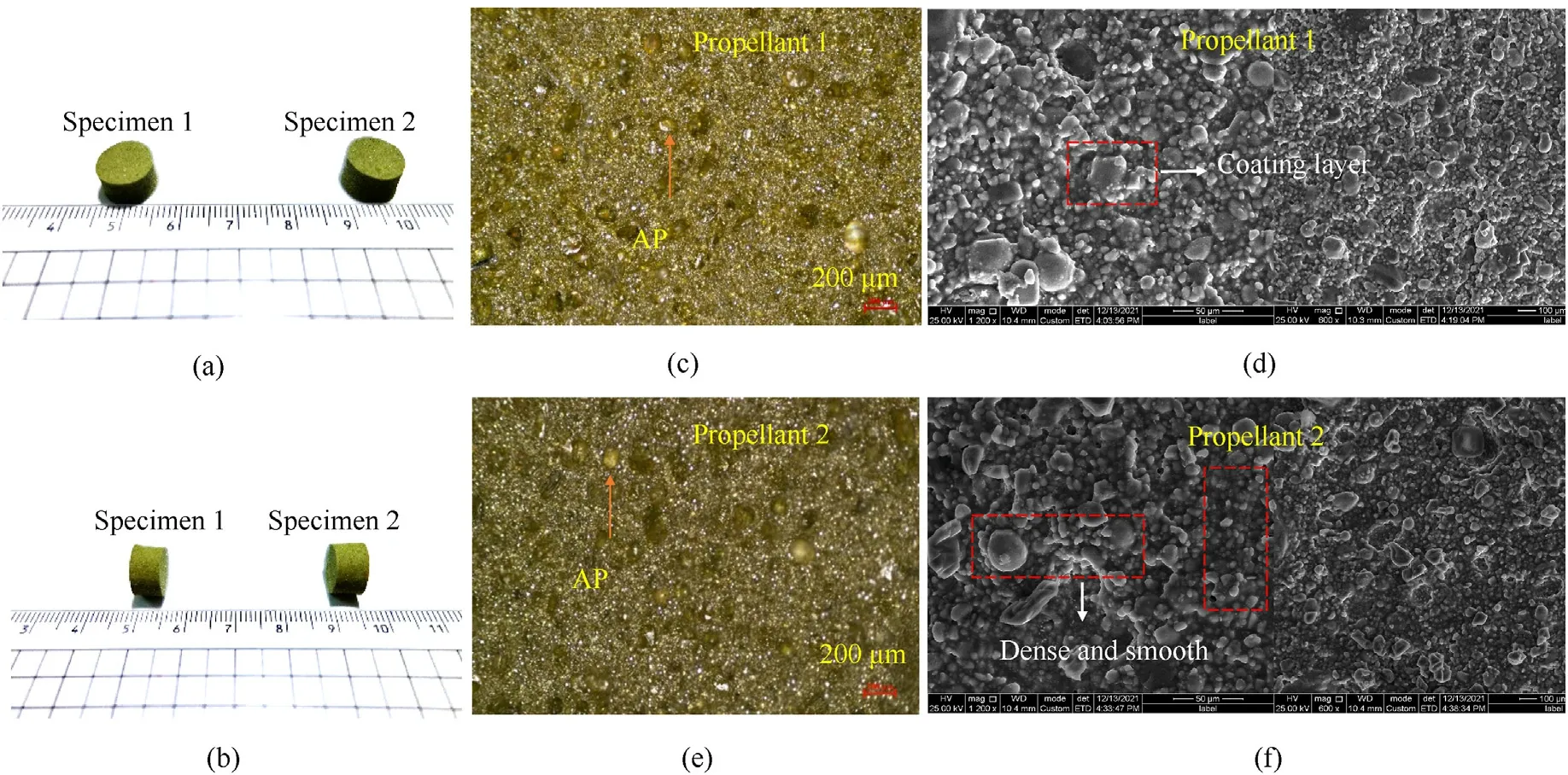
Fig.1.The prepared two types of propellants (a) and (b) and micro-morphology using OM (Optical Microscopy) (c) and (e) and SEM (Scanning Electron Microscopy) (d) and (f).
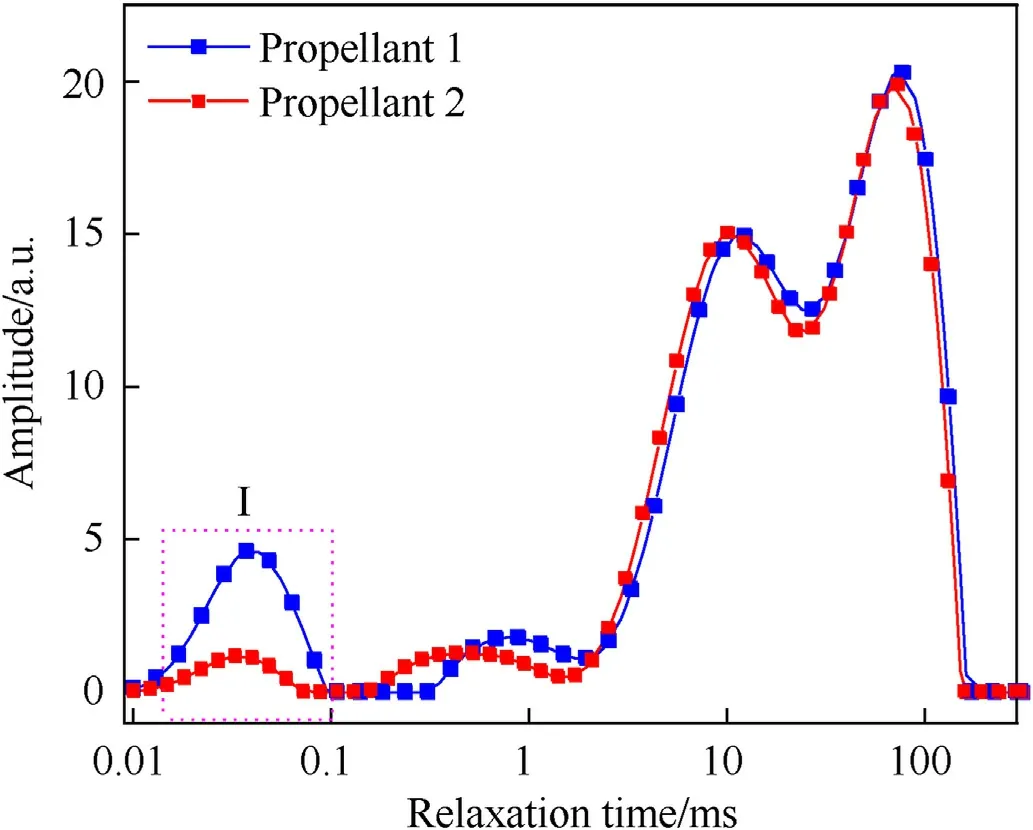
Fig.2.T2 distribution inversion results of propellants with different crosslinking density.
The previous work proves that SHPB device is an effective dynamic test method for propellant [46].The working principle is to define the relationship between strain rate,engineering strain and engineering stress of the modified propellant according to the signals collected by the data acquisition instrument shown in Eq.(1).
where, A1, c0,ρ and E are the cross-sectional area, wave velocity,density and Young's modules of the bars,respectively.l0and A2are the length and cross-sectional area of the modified propellant before tests.εrand εtare the collected strain signals of incident bar and transmitted bar.σ, ε and ˙ε respectively represent the real stress,real strain and strain rate of the modified propellant during loading;τ represents the duration of stress wave on the right side of the incident bar.
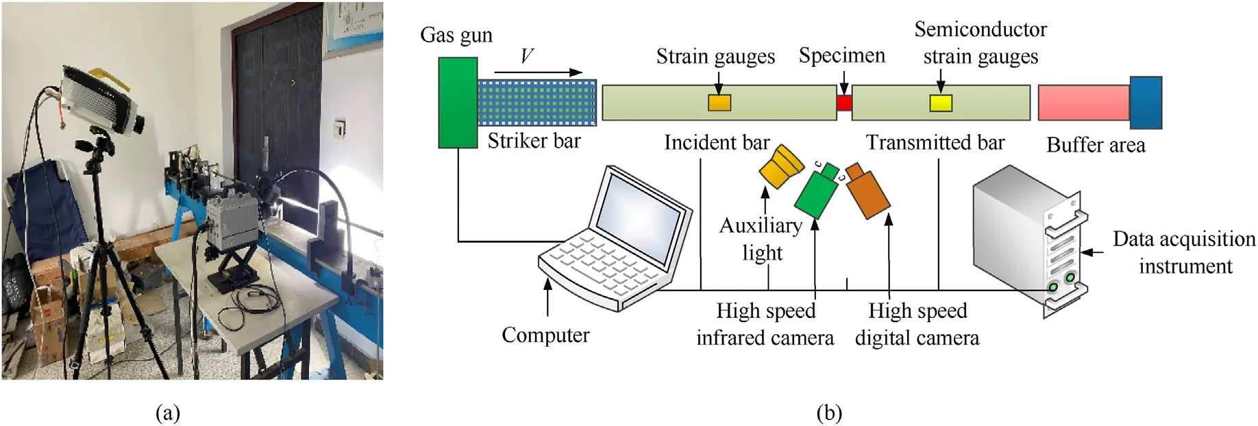
Fig.3.(a) A modified SHPB system.(b) Schematic diagram of the modified SHPB.
During the SHPB tests, the pressure value of striker bar can be recorded as 0.05 MPa,0.065 MPa,0.08 MPa,0.1 MPa,corresponding to the strain rates of 3600 s-1, 4500 s-1, 5400 s-1, 6000 s-1,respectively.Moreover,at least five repeated tests were carried out at each strain rate to ensure the repeatability of the dynamic loading tests.
3.Results and analysis
This part mainly analyzes the content: (1) The mechanical responses of propellants with different crosslinking densities under different strain rates; (2) The damage and ignition responses of propellants under different strain rates;(3)The failure and ignition mechanism from microscopic scope.
3.1.Mechanical responses
3.1.1.Stress equilibrium and constant strain rate
To satisfy the assumptions of stress equilibrium and constant strain rate in the SHPB theory, every dynamic test requires to be verified to guarantee the stress-strain characteristics are inherent to the propellants.
The stress equilibrium of the modified propellant was analyzed experimentally.All three pulse, εiεrand εtwere recorded by the semiconductor strain gauge and a resistance strain gauge.The starting point of each pulse is determined through data processing.As shown in Fig.4(a), the three recorded pulses move to an equivalent starting point.In addition, the value of εtis showed in Fig.4(a), where the stress at the front end of propellant is εt(the sum of incident and reflected pulses).The stress at the back end of propellant is εt(transmitted pulse)collected by the semiconductor strain gauge.Fig.4(a)shows that the calculated εtduring the whole pulse duration is consistent with the calculated εtobtained by the semiconductor strain gauge.It shows that the forces at both ends of the propellants are almost equal during the SHPB test.Thus, the propellant satisfies the stress equilibrium assumption.
The strain rate and stress relationship history curves of the modified propellant are shown in Fig.4(b).While the strain is 0.05,the strain rate reaches the peak (point A).When the strain is 0.67,the stress reaches its peak(point B).The strain rate curve after point A is close to the plateau stage(strain rate of 6000 s-1).It shows that the assumption of constant strain rate is satisfied.
3.1.2.Dynamic mechanical responses analysis
The stress-strain relationship curve is the most important indexes for evaluating the dynamic mechanical properties of modified propellants.Hence, as presented in Fig.5, the engineering stress-strain curves of the modified propellants under different strain rates were evaluated.The two kinds of propellants exhibited strong rate dependent.The dynamic modulus (slope) and the maximum engineering stress(σm)clearly increased with increasing strain rates.In Fig.5(a) and Fig.5(b), when the strain rate is 6000 s-1, the maximum engineering strain is 0.68 and the maximal engineering stress(σm)is 4.27 MPa and 3.88 MPa for propellant 1 and propellant 2,respectively.At the strain rate if 6000 s-1,the dynamic modulus (slope) are 6.28 MPa and 5.71 MPa.Comparing the maximum engineering stress (σm) at other strain rates, when the strain rates are 3600 s-1, 4500 s-1, 5400 s-1for propellant 1, the maximum engineering stress (σm) value is 1.36, 3.25, 3.71 MPa,respectively in Fig.5(a).The maximum engineering stress (σm)value is 1.62,2.77,2.89,3.88 MPa for propellant 2 at the same strain rate from Fig.5(b), respectively.The literature indicates that the propellant becomes significantly stiffer due to the increase of crosslinking density from the macroscopic properties[47].Because the crosslinking density of propellant 1 is greater than that of propellant 2,the dynamic modulus(slope)of propellant 1 is higher.It is consistent with the experimental results.Obviously, the two types of propellants show different mechanical properties when the crosslinking density is changed.
3.2.Damage and ignition responses during stress wave propagation process
To further reveal the real-time damage-ignition mechanism of propellant 1 and propellant 2 under high strain rates, the deformation, damage and ignition evolution images of the propellants was recorded by the high-speed camera.
Fig.6-Fig.8 provide selected image sequence of the propellant 1 at different strain rates.From Fig.6,propellant 1 was sandwiched between the bars and sustained large deformation until 1840 μs,during which it underwent four times(0 μs,460 μs,920 μs,1840 μs)stress wave loading.From 460 μs, the transverse strain of propellant 1 increases significantly, which indicates a prominent lateral tensile stress in propellant 1 normal to the axial loading direction.Owing to the continuous loading of the stress wave,a macro-crack was initiated and gradually expanded to the interior area from 1920 μs to 1940 μs.Finally, propellant 1 occurs fracture at 2000 μs.The impact process can be summarized into four stages: multiple loading,crack initiation,crack propagation and ultimate fracture at the strain rate of 3600 s-1.
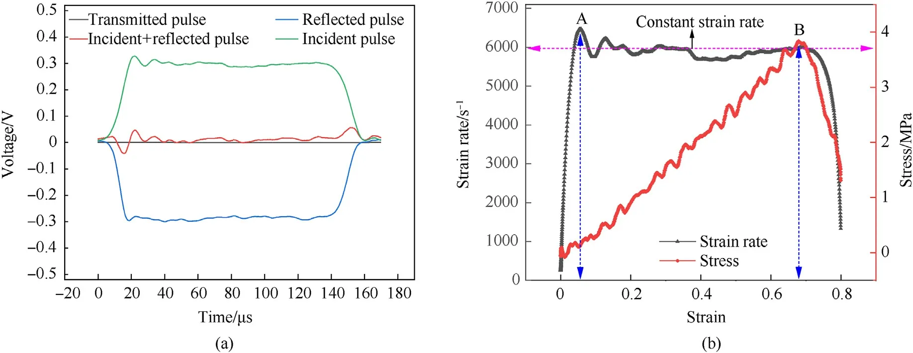
Fig.4.(a) Comparison of three recorded signals in the SHPB tests; (b) Strain rate-stress curves for propellants.

Fig.5.Engineering stress-strain curves under different strain rates (3600-6000 s-1).
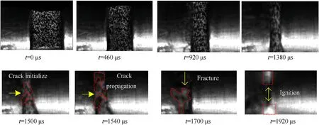
Fig.7.Selected image sequence of the modified propellant 1 in the strain rate of 4500 s-1.
In Fig.7,propellant 1 also undergoes four stress wave loads and four stages including multiple loading, crack initiation, crack propagation,and ultimate fracture at the strain rate of 4500 s-1.The difference from the strain rate of 3600 s-1is that a macro-crack was initiated and gradually expanded to the interior area from 1500 μs to 1540 μs.Finally, propellant 1 occurs fracture at 1700 μs during the third wave loading.Most important of all, ignition responses occurred at 1920 μs after entering the fourth stress wave loading.
In order to reveal the effect of strain rate on the damage-ignition evolution of propellant 1, the damage-ignition responses at strain rate 6000 s-1was studied in Fig.8.Propellant 1 underwent three stress wave loads and four stages.A macro-crack was initiated at 920 μs and gradually expanded to the interior area after 100 μs.The propellant 1 was ignited at 1420 μs after entering the third stress wave loading.The time of crack occurrence and ignition is earlier at strain rate 6000 s-1.The stronger ignition phenomenon suggests that the damage-ignition mechanism has obvious strain rate correlation.Combined with the analysis of images at different strain rates, crack propagation fracture plays an important role in propellant 1 damage-ignition evolution process.The critical ignition strain rate for the propellant 1 is 4500 s-1.
Fig.9 provides selected image sequence of the modified propellant 2 at strain rate of 3600 s-1.Compared with propellant 1,the most obvious difference of propellant 2 is that there is viscous flow in the process of stress wave loading without fracture phenomenon in Fig.9.When the stress wave was loaded for the fourth time in 1840 μs,propellant 2 showed rapid viscous flow.In 1920-2300 μs,it can be seen that the void is formed due to viscous flow.In addition, an obvious flow strip is formed instead of fracture at 2300 μs.It indicates that propellant 2 has higher ductility and toughness.Then, the ignition phenomena appeared at 2360 μs.Hence,the failure and damage-ignition mechanism of propellant 2 are differ significantly with propellant 1 when the crosslinking density is changed.To further understand the damage-ignition mechanism, studied at higher strain rates were carried out.
Fig.10 and Fig.11 show the selected image sequence of propellant 2 at strain rates of 5400 s-1and 6000 s-1respectively.From Fig.10, propellant 2 ignited in 1470 μs along with viscous shear flow.The ignition and viscous shear flow become more intense after 20 μs Specimen 2 experiences a rapid shear flow and formed a fracture angle but was not completely broken at 1500 μs.Finally,a second ignition occurred in propellant 2 with the arrival of the fourth wave loading.With the increase of loading strain rate to 6000 s-1, propellant 2 exhibits a faster shear flow phenomenon.Two ignition phenomena occurred during the third wave loading at 1060 μs and 1390 μs respectively.It is worth mentioning that the second ignition occurred when propellant 2 was completely detached at 1390 μs, which fully indicated that the interface debonding between AP particles and binder occurred.It is further proved that propellant 2 has higher ductility and toughness.The viscous shear flow plays an important role in propellant 2 damageignition process.

Fig.8.Selected image sequence of the modified propellant 1 in the strain rate of 6000 s-1.
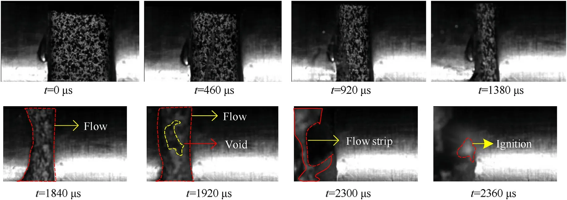
Fig.9.Selected image sequence of the modified propellant 2 in the strain rate of 3600 s-1.

Fig.10.Selected image sequence of the modified propellant 2 in the strain rate of 5400 s-1.

Fig.11.Selected image sequence of the modified propellant 2 in the strain rate of 6000 s-1.
By comparing the dynamic damage-ignition mechanism of propellants with different crosslinking density under different strain rates.It is preliminarily assumed that the damage-ignition mechanism of propellant 1 is crack generation, propagation and final fracture(ignition),while propellant 2 is viscous shear flow.To test the conjecture, the failure and ignition mechanism from microscopic scope are carried out.
3.3.Failure and ignition mechanisms at microsopic scales
The propellant 1 ignites when dynamic loading strain rate is greater than 4500 s-1.With the increase of loading strain rates,the ignition phenomenon becomes more intense.The high-speed camera image showed that the damage-ignition dominant mechanism of modified propellant 1 is crack formation, propagation,fragmentation and even ignition.In order to further verify the damage-ignition mechanism of propellants, the microstructure of post-test modified propellants were observed by SEM.Fig.12 shows the microstructure of modified propellant 1 in different strain rates.When the strain rate was 6000 s-1, propellants after the test was not collected due to the complete reaction.The posttest SEM images of propellant 1 in different strain rates show obvious particle breakage.By comparing the initial morphology of modified propellant 1(Fig.1(d)),the most significant characteristic of failure mode is particle breakage (see Fig.12(a)-Fig.12(c)).
By comparing the SEM images of propellant 1 at different strain rates, three remarkable failure characteristics in propellant 2 are:(1) The initial morphology is dense and smooth, resulting in grooves of different depth (see Fig.13(a)).(2) Particles such as AP and RDX are further coated with binder during loading (see Fig.13(a)and Fig.13(c)).(3)The shear flow strips are formed during loading (see Fig.13(b)).It is further proved that the ignition mechanism of propellant 2 is viscous shear flow.In conclusion,there are obvious differences in failure modes between propellant 1 and propellant 2, namely crack formation, propagation, fragmentation and even ignition and viscous shear flow mechanism.At the same time, propellant 2 has higher ductility and toughness.

Fig.12.The microstructure of modified propellant 1 at different strain rates: 3600 s-1; (b) 4500 s-1; (c) 5400 s-1.

Fig.13.The microstructure of modified propellant 2 at different strain rates: (a) 3600 s-1; (b) 4500 s-1; (c) 5400 s-1.
4.Discussion
The above experimental results show that the ignition mechanism of modified propellants with different crosslinked densities is different.There is evidence that those fresh local ignition sites of propellant 1 in Figs.7 and 8 are caused by crack generation,propagation and final fracture.Figs.9-11 show that the ignition mechanism of propellant 2 is caused by the friction generated by viscous shear flow during the impact process.
The radiative temperature evolution of the modified propellants with different crosslinked densities were recorded by the highperformance infrared camera.The maximum radiative temperature and the bulk average radiative temperature in the propellants at the strain rate of 6000 s-1in Fig.14.We selected the infrared images at different times according to the damage-ignition mechanism analysis.The bulk average radiative temperature of propellant 1 and propellant 2 are 53.46°C and 55.03°C respectively,while the maximum radiative temperature are 69.82°C and 70.54°C,which cannot reach the ignition temperature.The results of infrared radiative temperature analysis show that the ignition of the propellant is caused by hotspot-ignition mechanism.Therefore,it is proved that different hotspot-ignition mechanisms can generate sufficiently high temperatures during the impact process.The above analysis of temperature changes caused by hot spot mechanism will be analyzed in the following by theoretical calculation.
Considering the composition of the modified propellants, this paper assumes that the flow of heat is linear and modified propellants with different crosslinking density takes AP particles as the main component.Temperature variation caused by frictional heating in propellant 1 comes from crack friction and particle breakage, while propellant 2 comes from particle breakage and viscous shear flow friction.The resulting temperature change consists of two main parts: (i) First stage: the frictional heating when the modified propellants are deformed to diameter of the bar;(ii)Second stage:the shear frictional heating generated due to modified propellant being extruded in Fig.15 and Fig.16.
The temperature change (ΔT) at the dynamic loading process after a time interval of t seconds is given by Eq.(4) [48]
where k,ρ and C are the thermal conductivity,density and specific heat.F is the rate of generation of frictional heat per unit area per second of AP particles in modified propellants with different crosslinked density.Meanwhile, the parameter values are k=0.23 J∙s-1∙m-1∙K-1,ρ=1.8 g/cm3and C=1.256 J∙kg-1∙K-1.To estimate the value of F0, the yield stress and ultimate stress are assumed to be the maximum compressive stress generated by the no ignition reaction (first stage) and the ignition reaction (second stage).In addition,the inter-facial friction coefficient and a friction velocity are 0.4, 20 m/s, respectively.The yield stress and ultimate stress values come from the stress-strain curves.

Fig.15.Schematic diagram of propellant 1 two-stage heat generation principle.

Fig.16.Schematic diagram of propellant 2 two-stage heat generation principle.
Based on the damage-ignition images analysis,the temperature rises of propellant 1 with strain rates 3600 s-1and 4500 s-1were calculated (just consider frictional heating).The temperature increases in the two stages are 201.90°C and 308.12°C,respectively.The temperature value reaches reaction temperature of AP particles in propellant 1 when the strain rate is 4500 s-1.For propellant 2,the temperature change at the strain rate 3600 s-1is 298.52°C.In addition, the energetic components of the propellant continue to react chemically as the temperature increases, further increasing the temperature leading to local ignition.
Through theoretical analysis,further revealing that the damageignition mechanism of propellants with different crosslinking density is different.(i) Propellant 1 is particle breakage and crack friction.Propellant 2 shows a more obvious viscous shear flow mechanism.(ii)For propellants 1,the critical ignition strain rates is 4500 s-1.
5.Conclusions
This paper investigated the dynamic mechanical responses and damage-ignition mechanism of the modified propellants with different crosslinking densities at different strain rates by SHPB technique combined with a high-performance infrared camera and high-speed camera.The dynamic mechanical responses, damageignition mechanism, microstructure characterization and theoretical temperature change of the propellants were discussed by experiments and theoretical analysis.
The dynamic mechanical responses and damage-ignition mechanism of the two kinds of propellants exhibit a significant rate dependent.The dynamic modulus and the maximum stress increased with increasing strain rates.The ductility and toughness of propellant 2 with higher crosslinking density is better than the propellant 1.The damage-ignition mechanism for propellant 1 is crack generation,propagation and final fracture while viscous shear flow friction for propellant 2.For propellant 1, the critical ignition strain rates are 4500 s-1.The analysis of the microstructure after the test is helpful to further understand the damage-ignition mechanism of propellants.Combining with the experimental results, theoretical calculation also reveals the damage-ignition mechanism and the critical ignition strain rates of the propellants.
In the next work, a constitutive model is to be established,which includes the viscous shear flow and frictional heating mechanism, accounting for the deformation, damage-ignition mechanism and stress wave propagation process of modified propellants in different strain rates by a numerical simulation method.
Declaration of competing interest
The authors declare that they have no known competing financial interests or personal relationships that could have appeared to influence the work reported in this paper.
Acknowledgements
The authors would like to thank China National Nature Science Foundation (Grant No.11872119) and Foundation Strengthening Project(Grant No.2020-JCJQ-ZD-220) for supporting this project.
杂志排行
Defence Technology的其它文章
- Eigen value analysis of composite hollow shafts using modified EMBT formulation considering the shear deformation along the thickness direction
- Synthesis of energetic coordination polymers based on 4-nitropyrazole by solid-melt crystallization in non-ionization condition
- RDX crystals with high sphericity prepared by resonance acoustic mixing assisted solvent etching technology
- Study of residual stresses and distortions from the Ti6Al4V based thinwalled geometries built using LPBF process
- Modeling and simulation of solvent behavior and temperature distribution within long stick propellants with large web thickness undergoing drying
- Assessment of the ballistic response of honeycomb sandwich structures subjected to offset and normal impact
