Study of residual stresses and distortions from the Ti6Al4V based thinwalled geometries built using LPBF process
2023-11-11JgtheeshkumrRgurmnSivPrsdAVSNgeshChndrsekhr
Jgtheeshkumr S , Rgurmn M ,*, Siv Prsd AVS , Ngesh B K ,Chndrsekhr U
a Indian Institute of Information Technology Design and Manufacturing, Kancheepuram, Chennai 600127, India
b Gas Turbine Research Establishment, DRDO, Bengaluru 560093, India
c Wipro3D, Bengaluru, 560058, India
Keywords:Ti6Al4V Thin-walled geometry Residual stress Inherent strain XRD Ansys additive print
ABSTRACT The current paper focuses on the prediction of residual stresses and distortions in the Laser Powder Bed Fusion (LPBF) built Ti6Al4V thin-walled geometries using Ansys Additive Print (AAP) software which employs a layer-by-layer accumulation of inherent strain to calculate the deformations.Isotropic and anisotropic strain scaling factors were calibrated initially within the APP software for the Ti6Al4V based single cantilever beam geometry.Subsequently, the numerical simulations were performed in APP software and computed the residual stresses and distortions for the varied process parameters including laser power, scan speed and hatch distance while maintaining the layer thickness constant for all the design iterations.The numerical predictions were compared;they were found to match reasonably well with the XRD measurements within the calibrated regime.
1.Introduction
Additive Manufacturing (AM) is gaining widespread interest among the aerospace,automotive,defence,biomedical researchers due to its substantive potential for component realization with complex geometries [1-3].Within the realm of AM, Laser Powder Bed Fusion (LPBF) have created niche for producing metallic components in the above mentioned domains,more specifically in the aerospace applications.Hence, the LPBF process has been chosen for this present study.The schematic diagram of LPBF process is shown in Fig.1,in which the material is heated in a localized region and then rapidly cooled to form a dense geometry.The realization of parts in this process are subject to multivariate framework of functionalities, the most prominent of which laser-powder interaction, dynamics of melt pool, process-induced thermal gradients and ensuing phase transformations are dominant aspects [4,5].
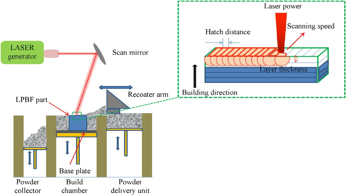
Fig.1.Schematic of LPBF process.
Temperature history experienced by the material defines its microstructure which influences the mechanical properties of built components/structures.Furthermore, the significant thermal strains involved in the LPBF process generate a high level of residual stresses and distortions which affecting the mechanical properties as well as causing geometrical inaccuracies in the final built part[6].Hussein et al.[7] studied the temperature and stress fields in the single layer modeling with 316 L stainless steel powder without considering the support structures;it has been found that the scan speed has significant effect on the melt pool length and the repeated melting and cooling in the scanned tracks leads to higher stresses in the built layers.Yadroitsev et al.[8] investigated the residual stress of SLM built 316 L steel and Ti6Al4V parts through experimental and numerical simulations.It was noted from this study that higher magnitude of tensile residual stress was observed along the scanning direction than its perpendicular direction for all specimens irrespective of the height of the specimen.Gu and He[9]were developed the simulation guidelines for predicting the residual stress in the Ti-Ni two component materials.It was found that the maximum stress was at the point where the sample joins with the substrate.Ghasri Khouzani et al.[10] experimentally measured the residual stress and distortion of 316 L steel components using neutron diffraction and Coordinate Measuring Machine respectively.A large tensile in-plane stress(up to ≈400 MPa)near the as-built disk top surfaces and found a marked break down of self-similarity in the residual stress distribution and the magnitude of in-plane residual stress decreased to 330 MPa after removal of support structure and the substrate.Otubusin et al.[11]studied the influence of build orientation,position of flange and wall thickness on the possible distortion of LPBF built IN625 compressor outlet vane.It can be noted that there has been a significant influence of flange position and wall thickness on the distortion in the thin wall compressor outlet vane.Therefore, the prediction and/or measurements of residual stresses and distortions in the LPBF built parts are very important and challenging due to complex physics phenomena involved in the process.It can be predicted using experimental,analytical and numerical techniques.Amongst these techniques,numerical simulations based on Finite Element Method(FEM) are gaining great attention for quick prediction of residual stresses and distortions prior to building the parts in the LPBF process,thereby reducing product lead-time[12].It is noted that(i)thermo-mechanical analysis and(ii)inherent strain method are the two most commonly used approaches for establishing the relationship between residual stresses and distortions with the LPBF process parameters.Shen and Chou [13] developed a 3D thermomechanical model and performed analysis in a single scan path with the effect of power characteristics and the results including the evolution of part residual stress were compared with the literature data for further validation.Yingli et al.[14]investigated a multi-track multi-layer SLM process using a 3D coupled thermomechanical analysis.The model accounted for the effect of heating, vaporization, cooling and shrinkage phenomenon.The results showed that the magnitudes of residual stress in the build direction increases with increasing number of layers.Delinger and Irwin[15]developed a combined hybrid inactive finite element activation strategy with adaptive coarsening to predict the residual stress for the large parts consisting of 107 layers.The numerical results were validated with experimental results and showed a maximum deviation of 29%.It is observed from Ref.[16]that most of the studies simulate single layer track with due requirement of extensive computational power to handle the non-linearity and phase change uncertainty of the materials.In summary, the thermo-mechanical method used for predicting residual stress in the LPBF process are not effective with respect to computational efficiency for analyzing the industrial sized-components.
Inherent strain method is a capable method for predicting the residual stresses in a full-scale components or parts by applying the residual plastic strain tensor to each layer of a macro-scale mechanical model[16-19].It is also noted that a number of simulation tools including Simufact,Ansys Additive Print(APP),Additive Suite,Autodesk Netfabb and Siemens 3D AM are commercially available to predict residual stresses and distortions.APP is the most popular commercial software among the other listed tools[20,21],therefore APP has been chosen as a software tool in the current study.The calibration study was carried out to obtain the isotropic and anisotropic strain scaling factors which are required as input parameters in the model.Ti6Al4V based single cantilever geometry was selected as it finds several applications in aerospace engineering,for example,aero-engine compressor components having several thin-walled features.Due to high thermal gradients involved in the process and thin-walled geometric nature, the excessive residual stresses and distortions are induced in the LPBF built parts.Therefore, the present research was focused on the prediction of residual stresses and distortions and establishing the relationship between the LPBF process parameters (such as laser power, scan speed and hatch distance) for the LPBF built Ti6Al4V thin-walled geometries.
2.Numerical modeling and analysis
Ansys Additive Print(AAP)has been selected as a software tool for numerical modeling and analysis of Ti6Al4V material based single cantilever beam thin-walled geometry to establish the relationship between LPBF process parameters and the associated residual stresses and distortions in the built part.The procedure followed for the same is shown in Fig.2.AAP uses inherent strain modeling approach to predict the residual stress and distortion for each layer of the part.The inherent strain value mainly depends on the machine,material and process parameters.The inherent strain value can be obtained from the experimentation as well as simulation and these values are the input for the part simulation.
2.1.Simulation framework
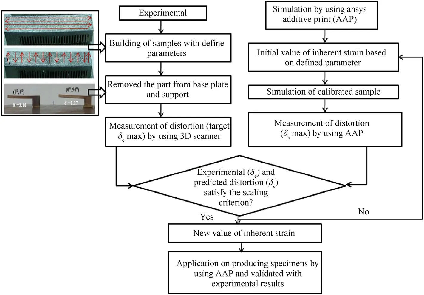
Fig.2.The numerical approach of the current study.
Ansys Additive version 2021 R2 has been used in the present study for performing the analysis to predict the residual stress and distortion.CAD model of the single cantilever thin-walled geometry with wall supports was generated in Solid works and the same was imported as.STL file format to the AAP environment as shown in Fig.3.Voxel size of 0.25 mm was chosen for meshing the geometry as per the guideline given in Ref.[22].Ti6Al4V alloy mechanical properties were assigned using bilinear isotropic hardening J2-plasticity model as listed in Table 1 [22].Gaussian heat flux was imported on the top surface of the powder bed with constant velocity and the bottom of the base plate was fixed.
2.2.Calibration of strain scaling factor and Anisotropic Coefficients
The calibration of Strain Scaling Factor (SSF) and Anisotropic Coefficients(ASC)would help to improve the prediction accuracy of machine and material specific information.These values were calibrated experimentally by building two identical single cantilever beam geometry using different scan patterns(0°,0°)and(90°,0°)as shown in Fig.4.The cantilever geometries were built directly on to the base-plate and supports were provided only in the overhanging region with yield strength ratio of 1.The process parameter as in Table 2 was used for the calibration study.
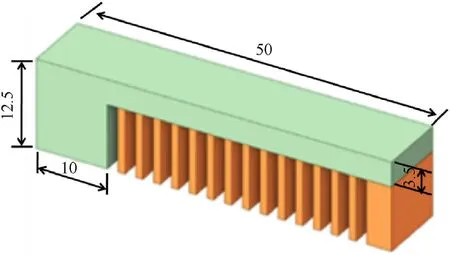
Fig.3.CAD model of the single cantilever geometry with wall supports.

Table 1Ti6Al4V material input data for AAP [22].
As built cantilever geometries were separated from the baseplate using wire-cut EDM process as shown in Fig.5.Wire-cut EDM is a preferred method because it will not induce any extra residual stress during cutting operation[23].The laser scanner was used to measure the distortion of the cantilever geometry.The measured distortion(δe)for(0°,0°)and(0°,90°)scan strategies are 3.16 mm and 1.17 mm respectively.The simulation was carried out under the similar experimental condition for the scan patterns(0°,0°) and (90°, 0°).The default values for SSF (SSF0:1) and ASC(ACS0:1.5,0.5,1)were used for the first iteration.The new SSF and ASCs were obtained from comparing the numerically predicted distortion (δs) values with the measured distortion (δe) from the calibration study [20,24].The process was continued until the updated SSF and ASC’s to converge to an acceptable level of error between simulation and measured distortion.The calibrated SSF and ASC’s are listed in Table 3 for thermal strain mode with a relative error of 7.7%;these calibrated values shall be used as input for the subsequent simulations.
2.3.Distortion and residual stress prediction using AAP
Response Surface Methodology(RSM)based Central Composite Design (CCD) experimental design has been used to optimize the process parameters for predicting on-plate residual stress and distortions.The DOE was generated using three different process parameters at three levels as listed in Table 4.

Fig.4.(a) LPBF built single cantilever geometry; (b) Scan pattern 0°, 0°; (c) 90°, 0°.

Table 2The input process parameters used for calibration.
Numerical simulation was carried out with the calibrated SSF and ASC values as listed in Table 3 for twenty different cases based on the DOE in Table 4 and the results are compared in Table 5.
The slicing stripe width of 5 mm and the scan strategy of starting layer angle of 0°with 67°rotation angle between the subsequent layers were followed for all simulation trials.The input energy density was computed using the relation(1)and the values are listed in Table 5.
where,E is the volumetric energy density(in J/mm3),P is the laser power (in Watts), S is scan speed(in s), H is the hatch distance (in mm) and t is the layer thickness (in mm).On-plate residual stress and distortions were obtained for all the DOE cases in APP as listed in Table 5.Energy densities are varied from 35 to 80 J/mm3for all the cases considered.Amongst all,the run#2,run#12 and run#15 were selected for the experimental evaluation to cover the entire spectrum of energy densities considered.
3.Experimental study
The Ti6Al4V based single cantilever beam geometries were 3D printed using EOSINT 280 machine considering different energy densities (low with run #12, medium with run #15 and high withrun#2 according to Table 5);XRD measurements of residual stress and distortions were also performed for the chosen run orders.The details of the sample preparation and observations and validation of numerical results with the experimental results obtained from XRD measurements are discussed in this section.

Table 3Calibrated SSF and ASC values for thermal strain mode analysis.

Table 4Process parameters and factor levels considered for DOE.
3.1.Sample preparation
Gas atomized Ti6Al4V alloy with particle size in a range from 20 to 50 μm has been used in this study.Ti6Al4V based single cantilever geometries were produced using metal 3D printing machine EOSINT M280 as shown in Fig.6(a).This system is outfitted with an Ytterbium fiber laser that operates at a wavelength of 1075 nm with nominal power of 200 W.The base-plate(made up of Ti6Al4V alloy)with dimensions of 250 × 250 × 25 mm was used in a preheated condition to a temperature of up to 35°C.The laser spot size of 100 μm at the focus was set.During the process, argon gas was supplied at a constant velocity and the oxygen level was maintained to below 0.1% in the machine chamber.The samples were built for run order #2, #12 and #15 were built in the same baseplate as shown in Fig.4(b).

Fig.5.Supports removed using WEDM.

Table 5On-plate distortion and longitudinal residual stress obtained from APP after analysis.

Fig.6.(a) EOSINT M280 LPBF machine; (b) LPBF built cantilever samples for different run order #2, #12 and #15.
3.2.Experimental measurement
X-Ray Diffraction (XRD) based residual stress measurement on the surface of single cantilever beam specimen as-built condition was performed by using proto XRD machine as shown in Fig.7.The lattice spacing of the Ti-α{213} was calculated using Cu_Kα radiation source and the parameters listed in Table 6 were set for XRD measurements.In each sample,three locations were selected at top surface of the cantilever beam at a height of 12.5 mm for measuring the residual stresses as shown in Fig.8(a).Similarly, the on-plate distortion values of the cantilever samples were measured using laser scanner along the build direction(at X=0 and Y=5 mm)ofthe cantilever part as shown in Fig.8(b).The scanned.STL file obtained through laser scanner was compared with the original CAD geometry and distortion values were computed.

Table 6Parameters used for XRD residual stress measurement.
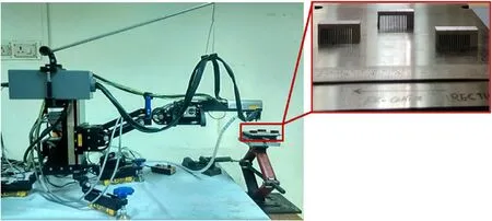
Fig.7.XRD measurement set to measure the residual stress.

Fig.8.(a) Location of residual stress along the longitudinal direction; (b) Location of on-plate distortion along the building direction.
4.Results and discussions
On-plate residual stress and distortion measurements on the Ti6AL4V based single cantilever beam geometry as-built from LPBF process was conducted using both numerical simulations and experimental measurements.The results obtained from these techniques are discussed in this section.
4.1.Validation of numerical results with experimental observations
Samples with low, medium and high energy densities (i.e.run order#2,#12 and#15 in Table 5)were built in the same base-plate as shown in Fig.6(b)to validate the numerically predicted results.Numerical predictions of residual stress along the longitudinal direction at three different locations(as seen in Fig.9)are compared with the XRD measurements in Fig.10;It conforms that the tensile stress was developed in the top layer of the built sample and the similar effect observed by Li et al.[25]for the LPBF built AlSi10Mg twin cantilever beams.During heating cycle, the top surface is willing to expand whereas the surrounding material does not permit; hence the elastic compressive strains are developed.During cooling,the compressed upper layers start shrinking and this is constrained by the previously built layers lead to tensile stresses on the top layer.Once the support is removed,the tensile stress in the top layer becomes compressive[25].It is noted from Fig.10 that the average percentage deviation between experimental results and numerical predictions for all three cases is ranging from 8.8 to 17%which is in the acceptable range for these types of study.
The total distortion before cutting the supports along the build direction was measured experimentally and compared the same with the numerical predictions as shown in Fig.11.It is noted from Fig.9 that a similar trend of distortion with good agreement(maximum distortion within 5% deviation) was observed.
4.2.Distortion prediction after support removal
Fig.12 shows the distortion profile after cutoff the support from the part.Among three cases run#2 possess higher cutoff distortion value of 0.68 mm.It is observed from Fig.12 that increase in laser power,decrease in scanning speed and hatch distance causes more energy imported on the powder.High energy input leading to a larger melt pool size and experiences the more thermal shrinkage which results in higher distortion within the part [26].
4.3.Development of predictive models
Regression analysis using minitab software was performed to obtain residual stress and distortion quadratic equations as a function of LPBF process parameters for the thin-walled geometry which is given in Eqs.(2) and (3).These equations will become a predictive tool for estimating the residual stress and distortion in the initial stage of the design before conducting experiments and numerical simulations.
Residual stress:
On-plate distortion:
where, P is the laser power, S is the scan speed, H is the hatch distance.The optimum parameter setting for the minimization of both residual stress and distortion was obtained as laser power:137 W,scan speed:1670 mm/s and hatch distance:013 mm with a composite desirability of D=1 and the optimum plot for the same is as shown in Fig.11.These optimum parameters were again verified through APP simulation and shown in Fig.13.It clearly indicates that the above given regression equations for residual stress and distortion prediction shall be used as a preliminary assessment guideline by the additive manufacturing industries and researchers as shown in Fig.14.

Fig.9.Residual stress measurement along the longitudinal direction: (a) Run #2 (E = 79.17 J/mm3); (b) Run #12 (E = 33.93 J/mm3); (c) Run #15 (E = 41.67 J/mm3).
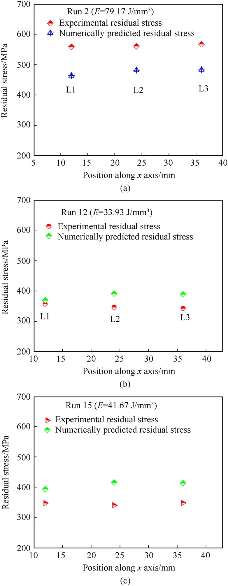
Fig.10.Comparison of residual stresses along longitudinal direction: (a) Run #2; (b)Run #12; (c) Run #15.
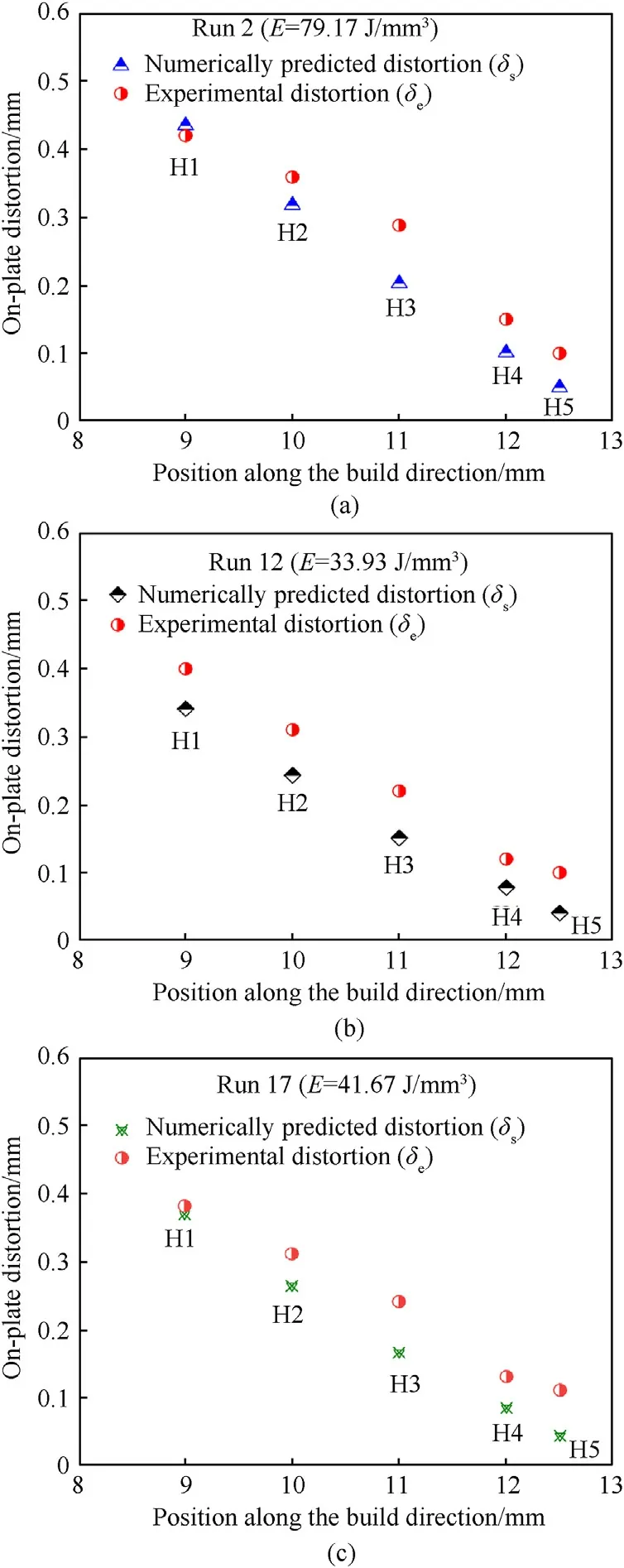
Fig.11.Comparison of distortions along the build direction: (a) Run #2; (b) Run #12;(c) Run #15.

Fig.12.Distortion profile after cutoff the support from the part.
5.Conclusions
A systematic guideline for predicting the on-plate residual stress and distortion of the LPBF built Ti6Al4V thin-walled geometries using AAP software has been developed and the same has been verified through XRD based experimental measurements.The key findings are summarized as below:
• The numerical predictions of both residual stresses and distortions were found to match well (3.3-20.4% deviation for residual stress and maximum distortion within 5%deviation)with the corresponding experimental results within the calibrated regime.
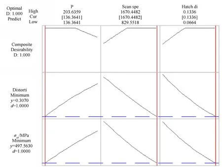
Fig.13.Optimization plot to minimize the residual stress and distortion.

Fig.14.Numerical prediction of maximum on-plate residual stress and distortion for the optimized process parameters.
• The effect of energy density (which is the function of laser power, scan speed and hatch distance) on residual stress and distortion predictions was studied using CCD method.It indicated that lowering of energy density is the better option for reducing the residual stress and distortion as seen in the study run order #12.
• Regression equations were derived for predicting the residual stress and distortion and the same was verified through numerical simulations.
Thus, the developed numerical scheme using AAP for residual stress and distortion predictions for the Ti6Al4V single cantilever thin-walled representative geometry can be used as potential tool which helps to identify the location and magnitude of part distortion.The distortions data can be compensated prior to actual building and be assured of a final part that conforms to design intend.
Declaration of competing interest
The authors declare that they have no known competing financial interests or personal relationships that could have appeared to influence the work reported in this paper.
杂志排行
Defence Technology的其它文章
- Eigen value analysis of composite hollow shafts using modified EMBT formulation considering the shear deformation along the thickness direction
- Synthesis of energetic coordination polymers based on 4-nitropyrazole by solid-melt crystallization in non-ionization condition
- RDX crystals with high sphericity prepared by resonance acoustic mixing assisted solvent etching technology
- Modeling and simulation of solvent behavior and temperature distribution within long stick propellants with large web thickness undergoing drying
- Assessment of the ballistic response of honeycomb sandwich structures subjected to offset and normal impact
- Few-shot object detection based on positive-sample improvement
