Tribological Properties of Ti-DLC Coatings on Piston-pin Surfaces
2023-10-07LIUJiliangXIANGJianhuaZUOZhengxingXIEGuoxinLUOJunSHENGYongqing
LIU Jiliang ,XIANG Jianhua ,ZUO Zhengxing ,XIE Guoxin ,LUO Jun ,SHENG Yongqing
(1. School of Mechanical Engineering, Beijing Institute of Technology, Beijing 100081, China; 2. College of Quality &Safety Engineering,China Jiliang University, Hangzhou 310018, China; 3. State Key Laboratory of Tribology, Tsinghua University, Beijing 100084, China; 4.Beijing Radiation Center, Beijing 100875, China)
Abstract: A magnetically filtered cathode vacuum arc deposition system was used to deposit Ti-doped diamond-like carbon coatings (Ti-DLC) on pin surfaces to improve the wear resistance of high-power density diesel engine piston pins.The coating structure,composition,and morphology were characterised using field emission scanning electron microscopy (FE-SEM),X-ray photoelectron spectroscopy (XPS),Raman spectroscopy,and other techniques.Friction tests were carried out using a universal tribometer to study the tribological properties of pins with or without coatings under dry friction and oil lubrication.The surface morphology and cross-sectional morphology of the Ti-DLC coating show that the coating has a uniform crosssection and good surface properties.The XPS spectrum shows that the coating contains Ti-C,Ti-C*,sp2-C,sp3-C,and C-O/C=O.Raman spectroscopy shows that there is an amorphous carbon phase in the Ti-DLC coating.The friction test shows that the friction temperature increase of the pin with the Ti-DLC coating is lower than that without the coating,especially under dry-friction conditions.At the end of the test,the difference in temperature increase is 16.7%.The friction coefficient when using high-viscosity lubricating oil with a coating is relatively lower than that without a coating,especially under low-speed and heavy-duty conditions.In the dryfriction state,the coated surface has better wear resistance than the uncoated surface,which primarily manifests as abrasive wear,and the surface without a coating mainly experiences adhesive wear.
Key words: high-power density diesel engine,piston pin,Ti-DLC coating,tribological properties
1 Introduction
The piston pin is a key component in internal combustion engines,which connects the piston and rod in an internal combustion engine and controls the friction power loss between the piston pin and connecting rod small-end bushing.Further,the power loss between the piston pin and piston hole cannot be neglected during calculations[1].With the development of efficient,energy-saving,and clean internal combustion engine technologies,the friction and wear of the piston-pin surface are facing new challenges[2].At present,the coating on the surface of the piston pin is an important method to reduce friction and wear.Among the widely used anti-wear coatings,diamond-like carbon (DLC)has been widely used in key parts of internal combustion engines owing to its low friction coefficient,high hardness,good wear resistance,and good chemical stability,such as the piston pin[3,4],piston ring[5],and valve tappet[6,7].With continuous improvements in the power density of the internal combustion engine,especially the development of a high-power density diesel engine,the piston pin must bear greater explosion pressures.However,the internal stress of the DLC coating is large,the film–substrate bonding force is relatively low,and the coating can easily fall off,limiting the application of the DLC coatings in high-power density diesel engines.
To mitigate the aforementioned issues,doping elements in DLC coatings is an effective method.Doping heterogeneous elements in DLC coatings can form chemical bonds with carbon elements,change the SP3/SP2 hybrid bond ratio of the film,change its chemical composition,microstructure,and mechanical properties,and effectively reduce the internal stress of the coating.The addition of carbonophilic elements(Ti,Cr,W,Mo,and Nb) can be distributed in the amorphous matrix in the form of atomic dissolution,elemental nanocrystals,or metal carbide nanocrystals to improve the mechanical strength and toughness of the coating[8,9].Ti-doped DLC coatings (Ti-DLC) have attracted extensive attention owing to their good filmbased bonding properties,mechanical properties,and tribological properties[10,11].Konkhunthotet al[12]doped 0.8 at% Ti in DLC;the coating showed high hardness,good corrosion resistance,and improved thermal stability.After comparing TiN,TiCN,and Ti-DLC,Zhanget al[13]found that the Ti-DLC coating’s surface roughness and friction coefficient were relatively the lowest.
The content of Ti has an important effect on the properties of Ti-DLC coatings.When preparing the Ti-DLC coating,Joet al[14]were able to control the Ti content by adjusting the flow ratio of Ar and C2H2.The results show that,with increases in the Ar flow ratio,the content of Ti increases,the surface roughness of the coating increases,and the ratio of SP2/SP3 increases.Ti doping greatly improves the bonding strength between the DLC coating and substrate.Cuiet al[15]prepared Ti-DLC coatings with different Ti contents by controlling the ratio of Ar and CH4.The results show that,when the Ti content is 0.41%,it has higher hardness and lower internal stress,friction coefficient,and wear rate.Chenet al[16]deposited the Ti-DLC coatings on tungsten carbide alloy steel lathe tools.The results show that the cutting performance and service life of the tools are improved.
By adjusting the deposition current of the Ti target,the Ti content in Ti-DLC coatings can also be controlled to achieve ideal coating properties.Zhouet al[17]showed that the atomic percentage of Ti varies greatly under different currents.At 1.82 wt%,the Ti-DLC coating had relatively low internal stresses and a high film-substrate bonding force and hardness.Guoet al[18]compared and analysed the friction coefficient and wear rate of Ti-DLC coatings deposited under two currents under dry friction and oil lubrication.Finally,it was found that,compared with the current of 3.5 A(Ti 27at.%-DLC),the current of 2 A (Ti4at.%-DLC) yielded better tribological performances for coatings under dry friction and boundary lubrication.Zhanget al[19]showed that the coating has a higher hardness when the current is 0.4 A,and a lower friction coefficient when the current is 0.3 A.Fenget al[20]studied the tribological properties of Ti-DLC coatings under the action of different ionic liquid lubricants,indicating that the lubricant has an obvious effect on the friction coefficient.Different Ti contents also indicate different surface roughness levels.With increases in the Ti content,the surface roughness tends to increase[21].
Based on previous studies,through the optimisation of coating preparation parameters,Ti-DLC coatings were deposited on the piston-pin surfaces of a high-power density diesel engine with a magnetically filtered cathode vacuum arc deposition system.The tribological properties were studied using a universal tribometer.The effects of the coating on the friction coefficient,friction temperature increase,and surface morphology of the pin under oil-lubrication and dry-friction conditions were investigated.
2 Experimental
The piston pin samples for the test were from a high-power density diesel engine.The core hardness was HRC 28-33,the external carburising depth was 0.5-1.3 mm,the HV was 664-840,and the surface roughnessRa was 0.039 ± 0.005 μm.The piston pin diameter was 43.994 ± 0.002 mm,and the length was 83.8 mm.A total of 10.5 mm was cut axially from the piston pin as the pin sample,and the sample was axially machined with a conical through-hole to facilitate installation on the friction test equipment.The diameter of the small end of the conical hole was 25.65 mm,and the cone angle was 17°.The bushing sample matched with the pin pair adopts the bushing blank of a certain type of high-power density diesel engine.The bushing hardness was HV 249-260.The inner diameter of the bushing was 44.059 ± 0.004 mm.The thickness of the bushing was 2.5 mm,and the inner surface roughnessRa was 0.5 ± 0.01 μm.The bushing and 40Cr base were interference assembled in a nitrogen environment to form the bearing sample,and the interference amount was 60 μm.The width of the bushing and base was 8 mm,and the outer diameter of the base was 69 mm.The hardness of the bushing base was HV 347-371.Two thermocouple mounting holes,both with a diameter of 1.5 mm and a depth of 5 mm were opened at the radial centre of the base,and the difference between the two holes was 180° in the circumferential direction.
The sample was cleaned ultrasonically in acetone and absolute ethanol,dried with high-purity N2,and then installed on the sample table of the magnetically filtered cathode vacuum arc deposition system to deposit the Ti-DLC coating on the outer surface of the pin sample.The Ti-DLC coating was deposited in a vacuum of 10-3Pa[22].The process was divided into four steps:the first step was Ti-ion implantation to enhance the sample’s surface strength and bonding properties.The high voltage was 8 kV,the beam current was 3 mA,and the deposition time was 10 min.The second step was Ti sputtering to enhance the bonding performance of the sample surface.The arc current was 90 A,the negative pressure was 800 V,and the deposition time was 2 min.The third step was Ti deposition,which forms the transition layer of the Ti-DLC coating.It improves the bonding performance of the coating.The arc current was 90 A,the negative pressure was 100 V,and the deposition time was 20 min.The fourth step was the Ti-DLC coating deposition,with an arc current of 90 A,negative pressure of 300 V,and deposition time of 180 min.C2H2gas was introduced into the deposition process,and the vacuum degree was 6×10⁻²Pa.
3 Characterisation of the coating
A part of the pin with the Ti-DLC coating was cut to facilitate insertion.After grinding and polishing,the cross-sectional morphology of the coating with the S-4800 field emission scanning electron microscope(FE-SEM) was observed.The test results are shown in Fig.1,which shows that the deposition structure of the Ti-DLC coating is uniform and well-combined with the substrate,with a section thickness of about 3.29 μm.The surface morphology of the coating was tested by the Zygo Nexview three-dimensional white light interferometer,and the results of which are shown in Fig.2.The figure shows that the coating surface is smooth,without large particles and impurities.The measured surface roughness is 0.047 ± 0.005 μm.After the Ti-DLC coating was deposited on the pin surface,the surface roughness increased,but it can be used for piston pin on high-power density diesel engine.

Fig.1 Cross-sectional morphology of Ti-DLC coating

Fig.2 Surface morphology of Ti-DLC coating
The observation samples were taken from the pin where the Ti-DLC coating was deposited,and the composition of the Ti-DLC coating was analysed using the Axis Ultra DLD X-ray photoelectron spectroscope(XPS).The XPS spectrum and peak-fitting spectrum of the Ti-DLC coating were obtained,as shown in Fig.3.Fig.3(a) shows that the asymmetric C 1s peak can be fitted as 281.8 ± 0.1 eV,282.8 ± 0.1 eV,284.3 ± 0.1 eV,285.2 ± 0.1 eV,and 286.5 ± 0.2 eV,corresponding to Ti-C,Ti-C*,sp2-C sp3-C,and C-O/C=O[23,24].The XPS spectrum of Ti2p exhibits the double peaks of Ti 2p1/2 and Ti 2P3/2,which can be divided into five peaks after Gaussian fitting.The peak positions are 454.7 ± 0.2 eV,455.4 ± 0.2 eV,461.4 ± 0.2 eV,456.8 ± 0.2 eV,and 462.5 ± 0.2 eV,as shown in Fig.3(b).The double peaks of 454.7 eV and 456.8 eV belong to TiC and Ti-O/Ti=O.There are two wide Ti-X peaks at 455.4 and 461.4 eV,which can be attributed to the nonstoichiometric TiC at the nc-TiC boundary[25-27].

Fig.3 XPS spectrum of Ti-DLC coating: (a) C1s,(b) Ti2p
The Ti-DLC coating was analysed with an HR evolution high-resolution Raman spectrometer equipped with a 532 nm laser.The Raman spectra and peak splitting fitting spectra of the Ti-DLC coating were obtained,as shown in Fig.4.The wide peak of the coating in the range of 1 000-2 000 cm-1is an amorphous carbon peak.Through Gaussian fitting,the results demonstrate a G peak near 1 571 cm-1and a D peak near 1 367 cm-1[28].Both peaks reflect the information of the sp2 cluster structure in an amorphous carbon film structure.The D peak originates from the respiratory vibration of the sp2 ring structure,while the G peak originates from the E2g central vibration mode of graphite.The Raman spectra demonstrated the existence of an amorphous carbon phase in the coating.
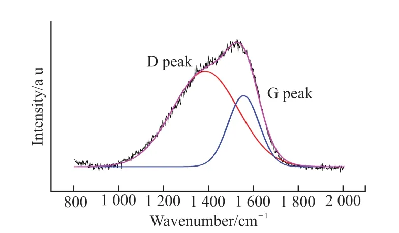
Fig.4 Raman spectrum of the Ti-DLC coating
4 Friction test
The Rtec MFT-5000 universal tribometer was used to carry out the friction test.The pin sample on the ring block drive shaft,the bearing on the selfdesigned fixture,and the fixture on the tappet were installed.A schematic of the friction test is shown in Fig.5.During the test,the shaft drove the pin to rotate and produce relative movement with the inner surface of the bushing.The sample was loaded in the vertical direction,and the horizontal pressure sensor tested the horizontal friction.During the oil-lubrication test,part of the sample was immersed in the oil pool.The volume of the oil pool was 1 L,and the immersion depth of the pin was 5 mm.The oil pool was removed during the dry-friction test.

Fig.5 Schematic of the friction test
The low-viscosity lubricating oil SAE 0W20 and high-viscosity lubricating oil SAE 20W50 were selected to comparatively test the tribological properties of the Ti-DLC coating under different oil-lubrication conditions.In addition,the comparison of the same working conditions was also carried out in the dry-friction state.The working conditions of the friction test are shown in Table 1.The test was divided into four steps:running in,medium-speed medium-load,high-speed light-load,and low-speed heavy-load.

Table 1 Friction test conditions
K-type thermocouples were installed in two holes on the bearing to analyse the friction temperature increase of the bearing.They were recorded as K1 and K2,respectively,where K1 was installed above the bearing near the friction area.In addition,the temperature of the lubricating oil and the ambient temperature were also monitored.The test process was photographed using a Fluke TiX580 infrared thermal imager to ascertain the temperature field of the sample.
5 Friction test results and discussion
5.1 Oil lubrication
5.1.1 Friction coefficient
After the running-in period,the friction coefficients under different sets of working conditions were obtained.Fig.6 shows the friction coefficient of fully lubricated SAE 0W20.It can be seen that,under working condition II,the friction coefficient was the highest and fluctuated greatly in comparison to other working conditions,irrespective of the existence of a Ti-DLC coating.At a higher rotating speed,the sample vibrated greatly.The lubricating oil film was not well-formed and did not act as a good damper due to the low viscosity of the lubricating oil,which increased the fluctuation of the friction coefficient.The friction coefficient fluctuation increased obviously with Ti-DLC coatings,given that the self-lubricating effect of the coating was reduced due to the presence of TiC in the coating.Under condition III,the friction coefficient was the most stable,with or without the coating.Its value was about 0.01.
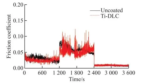
Fig.6 Friction coefficient of SAE 0W20 under fully lubricated condition
Fig.7 shows the friction coefficient of SAE 20W50 under the fully lubricated condition.Compared with SAE 0W20 lubrication,the fluctuation of the friction coefficient under working condition II was significantly reduced,particularly with the Ti-DLC coating.This showed that there is little difference in the friction coefficient with or without coatings under the action of high-viscosity lubricating oil.Under heavy loads,the Ti-DLC coating had a smaller friction coefficient.

Fig.7 Friction coefficient of SAE 20W50 under fully lubricated condition
5.1.2 Friction temperature
Four thermocouples were used to test the temperature of the SAE 0W20 friction test process under a fully lubricated state,and the results of which are shown in Fig.8.The indoor temperature was 28 ℃,and the temperature of K1 was always higher than that of K2 at given times.This is because K1 was close to the friction heat source,while K2 was further away.In addition,K2 was immersed in the oil pool,and its heat dissipation was relatively fast.Under working condition I,the temperature rose slowly with the progression of the test,and had little effect on the test temperature with or without coatings.At the end of this working condition,the temperature of K1 and K2 without the coating was 33 and 32 ℃.Under working condition II,the temperature increase was caused by the oil mixing when the pin rotates because of increases in the rotating speed.Then,K1 and K2 also increased rapidly,and the corresponding oil pool temperature also increased.At the end of this working condition,K1 without the coating was at 38.7 ℃,K2 was at 36.6℃,and K1 with the Ti-DLC coating decreased slightly,to 37.7 ℃.With the progression of test condition III,the temperatures of K1 and K2 decreased rapidly.At the end of the test,K1 and K2 without the coating were at 34 and 33.6 ℃,respectively,and K1 and K2 with the coating were at 32.8 and 32.7 ℃,respectively.The oilpool temperature with or without the coating was 31.8 and 30.3 ℃,respectively.The abovementioned results show that the rotational speed had a great influence on the friction temperature increase.The friction temperature increase of the sample with the Ti-DLC coating was slightly lower than that without a coating.

Fig.8 Temperature of SAE 0W20 under fully lubricated condition
The temperature-field photos of the test sample during the friction test were taken using an infrared thermal imager to visualize the temperature-field distribution of the test sample.Fig.9 shows the temperature-field distribution of the sample with or without the Ti-DLC coating at the end of different working conditions under the fully lubricated state of SAE 0W20.It can be seen that the temperature field of working condition II was significantly higher than those of working conditions I and III.The temperature-field distribution of the test sample was greatly affected by the lubricating oil.The lubricating oil rolled up by the pin rotation flows downward from the bearing clearance,and the lubricating oil flow area was an obvious high-temperature area.There was no obvious difference in the temperature-field distribution diagram with or without the Ti-DLC coating.

Fig.9 Temperature-field of fully lubricated SAE 0W20 under different working conditions: (a) State I,(b) State II,and (c) State III without a coating;(d) State I,(e) State II,and (f) State III with a coating
Fig.10 shows the friction temperature increase of fully lubricated SAE 20W50 with and without the Ti-DLC coating.It can be seen that the temperature change trend under different working conditions is similar to that in Fig.8,but the temperature rise differs significantly.In comparison to Fig.8,the temperature increase rates under working conditions I and II increase significantly.Without a coating,the temperatures of K1 and K2 are 39.4 and 38.1 ℃,respectively,at the end of condition I.At the end of condition II,the temperatures of K1 and K2 are 48.4 and 45.6 ℃,respectively.At the end of condition III,the temperatures of K1 and K2 are 38.6 and 38.4℃,respectively.The temperature with the coating is slightly higher than that without the coating.For example,at the end of condition II,the temperature without the coating is 0.4 ℃ higher than that with a coating.Under the same working conditions,the temperature under the fully lubricated conditions of SAE 20W50 is higher than that of SAE 0W20 owing to the different viscosities of lubricating oil.If the viscosity is higher,the heat generated by stirring the oil in the friction process increases,so the temperature increases.

Fig.10 Temperature of SAE 20W50 under fully lubricated conditions
Fig.11 shows the temperature-field distribution with or without the Ti-DLC coating at the end of different working conditions under the fully lubricated state of SAE 20W50.As shown,in comparison to the temperature distribution in Fig.9,the temperature increases under the same working conditions,and the distribution trend of the temperature field is similar.The temperature-field distribution under working conditions I and III is very obvious,and the temperature in the oil pool increases significantly.The temperature of condition II is still the highest,and there is an obvious high-temperature area on the sample and fixture.The presence of the Ti-DLC coating has little effect on the temperature-field distribution,and the temperature without the coating is slightly higher.

Fig.11 Temperature-field of SAE 20W50 fully lubricated under different working conditions: (a) State I,(b) State II,and (c) State III without a coating;(d) State I,(e) State II,and (f) State III with a coating
5.2 Dry friction
5.2.1 Friction coefficient
Fig.12 shows the friction coefficient with and without a coating in the dry-friction state.It can be seen that the difference in the friction coefficient under different working conditions becomes smaller than in the oil-lubrication state.The friction coefficient does not significantly increase because there is no need to overcome the resistance of the lubricating oil.The friction coefficient with the Ti-DLC coating increases slightly in comparison to that without a coating,primarily because of the cutting and sticking of wear particles in the friction process.Under condition II,the friction coefficient fluctuates greatly without the coating,indicating that there is significant adhesion.The friction coefficient of the Ti-DLC coating is relatively stable,but it also fluctuates greatly.This is because of the accumulation of coated wear particles in the gap between the pin and the bushing,where particles cannot be discharged from the gap in time.

Fig.12 Friction coefficient under dry-friction condition
5.2.2 Friction temperature increase
In the dry-friction state,the friction temperature increase trend differs from that under oil lubrication.Fig.13 shows the friction temperature increase curve under dry-friction conditions with or without the pin surface coating.Under the same working conditions,the temperature increase without a coating is significantly higher than that with a coating.When it is uncoated,there is no obvious temperature fluctuation during the transition from working condition I to working condition II,and then from working condition II to working condition III,which is very different under the conditions of oil lubrication.This is because,in the dry-friction state,the friction heat cannot be quickly dissipated through the lubricating oil,and the heat is retained within the sample and fixture.Therefore,the sensitivity of the working conditions to the temperature is reduced.With a coating,the temperature fluctuation during the transition from condition I to condition II is obvious because of the rapid speed increase in temperature of condition II relative to condition I,and the rapid increase in friction heat generation.However,the temperature of condition I is not high.Therefore,a large temperature difference can be observed.

Fig.13 Temperature under dry friction
At the end of working condition I,the friction temperatures of K1 and K2 without a coating are 40.9 and 39 ℃,respectively,and the friction temperatures of K1 and K2 with a coating are 35.8 and 34.6 ℃,respectively.At the end of working condition II,the friction temperatures of K1 and K2 without a coating are 46.4 and 44 ℃,respectively,and the friction temperatures of K1 and K2 with a coating are 40.2 and 39.9 ℃,respectively.At the end of working condition III,the friction temperatures of uncoated K1 and K2 are 43 and 41.8 ℃,respectively,and the friction temperatures of coated K1 and K2 are 35.8 and 35.5 ℃,respectively.It is found that the temperature of the coated sample is significantly lower than that of the uncoated sample at the end of condition III.This is because less heat is generated by the dry friction between the bushing and Ti-DLC.This shows that the Ti-DLC coating significantly reduces the friction temperature increase during dry friction,which significantly differs from the behaviour during oil lubrication.
Fig.14 shows the temperature-field distribution with and without the coating at the end of different working conditions under dry-friction conditions.It can be seen that,since there is no effect of lubricating oil,the temperature-field distribution differs significantly from that in Figs.9 and 11.There is a relatively hightemperature field on the surface of the fixture and pin,and the distribution is relatively uniform.It is also found that the temperature-field distribution of the sample and fixture differs,primarily because of the different thermal conductivities of the two materials.Under the same conditions,the temperature field in condition II is relatively high.Under different working conditions,the temperature-field distribution without a coating is relatively high.

Fig.14 Temperature-field for dry friction under different working conditions: (a) State I,(b) State II,and (c) State III without a coating;(d)State I,(e) State II,and (f) State III with a coating
5.2.3 Surface morphology
It is found that there is no obvious wear track on the friction surface of the pin and bushing under oillubrication conditions.Therefore,only the friction surface morphology in the dry-friction state is analysed.A high-definition CCD microscope was used to observe the friction surfaces of bushings and pins that were not cleaned after the dry-friction test.We observed the circumference of the bushing and pin for every 45°,obtaining the surface topography at eight positions,where the 0° position was the loading direction.
Fig.15 shows the morphology of the bushing friction surface when the pin surface is uncoated.Fig.16 shows the morphology of the bushing friction surface when the pin surface is coated.Figs.15(a) and 16(a)show that the width of the test bushing is 8 mm.The figure shows that the wear at the three positions in Figs.15(a),15(b),and 15(h) is severe,and there are obvious golden-yellow scratch marks on the surface.The wear tracks at the three positions in Figs.15(d),15(e),and 15(f) are shallow.The contact pressure position of the bushing is consistent with the aforementioned bushing wear track characteristics.The similarity between Figs.16 and 15 is that the wear at the three positions in Figs.16 (a),16(b),and 16(h) is more serious,and the wear at the other positions is relatively small.The biggest difference between Figs.16 and 15 is that there are different degrees of wear particles accumulated on the surface in Fig.16,especially in Figs.16(c) and 16(d),which is mainly due to the wear of the coating.From the bushing surface wear results,it can be seen that the wear in Fig.16 is significantly less than that in Fig.15.In other words,when Ti-DLC is deposited on the pin surface,the bushing wear is significantly reduced.

Fig.15 Surface morphology of the bushing (uncoated): (a)0°,(b)45°,(c)90°,(d)135°,(e)180°,(f)225°,(g)270°,(h)315°
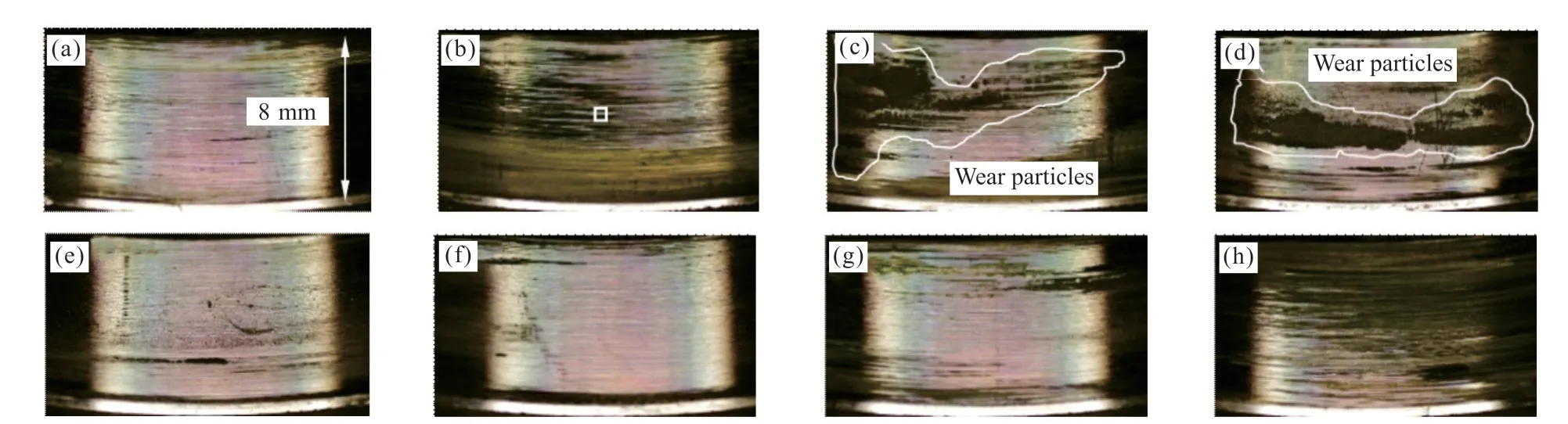
Fig.16 Surface morphology of the bushing (Ti-DLC coated) : (a)0°,(b)45°,(c)90°,(d)135°,(e)180°,(f)225°,(g)270°,(h)315°
The three-dimensional white light interferometer is used to observe the morphology of the central marked area in Fig.15(b) and Fig.16(b).The results are shown in Figs.17 and 18.It can be seen that the surface wear track in Fig.17 is larger than that in Fig.18.The cross-sectional profile at the dotted line position in Figs.17 and 18 is shown in Fig.19.The figure shows that the difference between the highest and lowest peaks of the contour without a coating is 4.3 μm.With the Ti-DLC coating,the difference is 2.1 μm.The figure shows that the contour curve without the coating is distributed above and below the reference line.Further,for the Ti-DLC coating,it is mainly distributed below the reference line.There are obvious rough convex peaks on the friction surface of the bushing without the coating,which is mainly caused by adhesion.When there is a coating,the friction surface of the bushing is mainly concave grooves,primarily because of the abrasive wear of the Ti-DLC coating.

Fig.17 Micrograph of the position marked in Fig.15(c) (uncoated)

Fig.18 Micrograph of the position marked in Fig.16(c) (Ti-DLC coated)

Fig.19 Profiles of the wear traces in Figs.17 and 18
Fig.20 shows the friction surface morphology of the uncoated pin.It is clear that there are obvious light-yellow wear marks on the different pin directions,indicating that the bushing is seriously worn and a lot of bushing material is transferred onto the pin surface.Fig.21 shows the friction surface morphology of the pin with the Ti-DLC coating deposited on the surface.The figure shows that there are very obvious wear marks on the left and right edges of the pin,but no coating is found to have fallen off.No transfer of the bushing material to the pin surface is found in the figure.Through the abovementioned comparative analysis,it is found that the wear mechanism of the pin surface without a coating is mainly adhesive wear,while that of the pin surface with the Ti-DLC coating is mainly abrasive wear.

Fig.20 Surface morphology of an uncoated pin: (a)0°,(b)45°,(c)90°,(d)135°,(e)180°,(f)225°,(g)270°,(h)315°

Fig.21 Surface morphology of a Ti-DLC coated pin: (a)0°,(b)45°,(c)90°,(d)135°,(e)180°,(f)225°,(g)270°,(h)315°
5.2.4 Energy spectrum analysis
The energy dispersive spectrometer (EDS)attached to the FE-SEM was used to analyse the elemental composition of the bushing before the friction test and the pin with or without the Ti-DLC coating both before and after the friction test.The test position of the pin after the test was marked as shown in Figs.20(b) and 21(b).The sample was cleaned with alcohol before testing.The atomic percentages of different samples observed are listed in Table 2,which shows that the main material of the bushing is Cu,while also containing a certain amount of Sn;it is a kind of tin bronze wear-resistant material.The material of the pin is mainly Fe,with some Cr detected,primarily as part of an alloy material.The content of C in the Ti-DLC coating is 64.74 at%.Further,the content of Ti is 16.21 at%.After the friction test,3.72 at% Cu was detected on the uncoated pin,which was obviously transferred from the bushing.However,it was not detected on the coated pin.This shows that the Ti-DLC coating plays a significant role in reducing the adhesion of the friction surface.It is also found that the content of O decreases,and the content of C increases.This shows that the Ti-DLC coating consumes the O in the coating during friction.The appearance of Fe indicates that the coating experiences a certain amount of wear;therefore,the substrate material is detected.The thickness of the coating can be increased to improve the wear resistance of the coating by increasing the coating deposition time.

Table 2 Atomic percentage of different samples/at%
6 Conclusions
Herein,a Ti-DLC coating was deposited on a pin.The tribological properties under oil-lubrication and dry-friction conditions were investigated by a friction test.The main conclusions that can be drawn are as follows:
a) The friction coefficient varies greatly under different working conditions.The friction coefficient is the highest under high-speed and light-load,and the lowest under low-speed and heavy-load.With the coating,the friction coefficient under the action of the high viscosity lubricating oil SAE 20W50 is lower than that of low viscosity lubricating oil SAE 0W20.
b) Under oil-lubrication conditions,the friction temperature increase with the Ti-DLC coating is slightly lower than that without the coating,while the friction temperature increase with the coating decreases significantly under dry-friction conditions.At the end of condition III,the friction temperature at the K1 position with or without a coating differs by 3.5%,2.3%,and 16.7%,respectively,under SAE 0W20 lubrication,SAE 20W50 lubrication,and dry friction.In condition III,the high temperature region of temperature-field distribution is the most obvious.
c) Under oil-lubrication conditions,there is no obvious wear track on the friction surface with or without the Ti-DLC coating on the bushing and pin.In the dry-friction state,when there is no coating,a large amount of copper material was transferred from the bushing wear,which adheres to the pin surface.Further,the bushing friction surface has obvious adhesion traces,which mainly manifest as adhesive wear.When there is a coating,no bushing wear material transfer is found on the pin surface,and the bushing friction surface mainly experiences abrasive wear.
d) The friction test shows that the Ti-DLC coating exhibits good friction temperature increase performance and wear resistance under different working conditions.The next work can consider depositing Ti-DLC coating on piston pin and applying it to high-power density diesel engine for further test.
Conflict of interest
All authors declare that there are no competing interests.
杂志排行

Journal of Wuhan University of Technology(Materials Science Edition)的其它文章
- Core-shell-embedded Mesoporous Silica Capsules for Atmospheric Water Harvesting
- Preparation of B2O3-ZnO-SiO2 Glass and Sintering Densification of Copper Terminal Electrode Applied in Multilayer Ceramic Capacitors
- Structural Characterization of Carbon-implanted GaSb
- Development of Eggshell Waste Incorporated with a Porous Host as a Humidity Adsorption Material
- Low Temperature Heat Capacity of Zn Substituted Cobalt Ferrite Nanosphere: The Relation between Magnetic Properties and Microstructure
- The Enhanced Electrons and Holes Separation for Bi2MoO6/TiO2 Z-scheme Heterojunction by Ag Loading