Polypyrrole-Coated Zein/Epoxy Ultrafine Fiber Mats for Electromagnetic Interference Shielding
2023-09-22DINGRunlong丁润龙QIRuirui戚瑞瑞LIUFeiLIUWanshuang刘万双ZHANGLiying张礼颖JIANGQiuran蒋秋冉
DING Runlong(丁润龙), QI Ruirui(戚瑞瑞), LIU Fei(刘 飞), LIU Wanshuang(刘万双), 4, ZHANG Liying(张礼颖), 4*, JIANG Qiuran(蒋秋冉)*
1 Key Laboratory of Textile Science &Technology, Ministry of Education, Donghua University, Shanghai 201620, China 2 College of Textiles, Donghua University, Shanghai 201620, China 3 Center for Civil Aviation Composites, Donghua University, Shanghai 201620, China 4 Shanghai Collaborative Innovation Center of High Performance Fibers and Composites (Province-Ministry Joint), Donghua University, Shanghai 201620, China
Abstract:To reduce the environmental pollution and meet the needs for wearable electronic devices, new requirements for electromagnetic interference (EMI) shielding materials include flexibility, biodegradability, and biocompatibility. Herein, we reported a polypyrrole-coated zein/epoxy (PPy/ZE) ultrafine fiber mat which was inherently biodegradable and skin-friendly. In addition, it could maintain its ultrafine fibrous structure after coating, which could provide the mat with mechanical compliance, high porosity, and a large specific area for high EMI shielding. With the assistance of the epoxide cross-linking, the breaking stresses of the PPy/ZE fiber mats could achieve 3.3 MPa and 1.4 MPa and the strains were 40.1% and 83.0% in dry and wet states, respectively, which met the needs of various wearable electronic devices. Along with the extension in the PPy treatment duration, more PPy was loaded on the fiber surfaces, which formed more integrated and conductive paths to generate increasing conductivities up to 401.76 S·m-1. Moreover, the EMI shielding performance was raised to 26.84 dB. The biobased mats provide a green and efficient choice for EMI shielding materials, which may be a promising strategy to address EMI problems in multiple fields.
Key words:polypyrrole(PPy); zein; ultrafine fiber mat; electromagnetic interference (EMI) shielding; electrical conductivity
0 Introduction
Nowadays, there has been a significant increase in the demand for wearable electronic devices and 5G facilities for numerous uplifting applications[1-2]. However, the ensuing electromagnetic interference (EMI) pollution is detrimental to the functionality and integrity of electronic and communication devices and may threaten human health[3-4]. Therefore, effective strategies for the EMI alleviation are in urgent demand. In the last decade, EMI shielding materials are emerging for EMI control[5]. The popular EMI shielding materials are mainly metallic or carbon-based, such as gold, silver, aluminum, copper, carbon fibers, carbon nanotubes, graphenes, and MXenes[6-11]. However, these materials suffer from bulkiness, easiness of corrosion, complicated processing, and a high percentage of reflection of electromagnetic waves (EMW) other than absorption[12-14]. The ideal EMI shielding materials should possess properties including lightweight, high shielding effectiveness, wide absorption frequency range, low EMI reflection, good flexibility, simple processing, and sufficient mechanical strength. Nowadays, more important needs include biodegradability to eliminate pollution after discarding and wearable-electronic-device-related applications with high skin suitability. Whereas, most EMI shielding materials lack biodegradability or biocompatibility.
In this work, the corn protein, zein, is used as the raw material of the base, which can endow inherent biodegradability and biocompatibility to the obtained EMI shielding materials. This method has the potential for large-scale production since zein is the byproduct of the ethanol industry. Electrospinning can easily produce porous ultrafine fibers with sufficient mechanical strength and has been applied to the manufacture of zein ultrafine fibers[15]. As a result, the ultrafine fibrous base is constructed via electrospinning to establish a flexible and highly porous structure with a low density and a large specific surface area for the EMW absorption and reflection. The drawback of the zein ultrafine fibers is their poor mechanical properties, especially when they are wetted. The epoxide with high reactivity to active hydrogen structure in protein was employed as the cross-linker for modification, which was reported to be effective for the mechanical strength elevation[15]. Instead of inorganic conductive materials, polypyrrole (PPy) is coated on the zein/epoxy (ZE) ultrafine fibers to form the organic conductive layer due to its sufficient conductivity, EMW absorbing dominant nature, mechanical compliance, biocompatibility, and simple processing[16]. This work investigates the relationship between the EMI shielding efficiency of the PPy-coated zein/epoxy (PPy/ZE) ultrafine fiber mats and their morphological properties, mechanical properties, and electrical conductivity.
1 Experiments
1.1 Materials
Zein powders were purchased from Hefei Bomei Biotechnology Co., Ltd., Hefei, China. Glycerol triglycidyl ether (GTE) was obtained from Weng Jiang Reagent Co., Ltd., Shaoguan, China. Polyvinyl pyrrolidone (PVP) and iron(III) chloride hexahydrate (FeCl3·6H2O) were supplied by Shanghai Aladdin Biochemical Technology Co., Ltd., Shanghai, China. Pyrrole (with a purity of 98% by weight) was purchased from Sigma-Aldrich, USA, and ρ-toluene sulfonate (ρ-TSA) with a purity of 97% by weight was obtained from Acmec Biochemical Co., Ltd., Shanghai, China.
1.2 Sample preparation
The PVP/ethanol solution was prepared by dissolving PVP into the ethanol-water solution at a weight ratio of 5∶100. The mass fracfion of ethanol in the ethnol-water solution is 75%. The spinning solution was obtained by mixing zein powders, GTE, the ethanol-water solution and the PVP/ethanol solution at 17.0%, 3.0%, 62.1% and 17.9% by weight, respectively. After stirring and aging for 24 h, the spinning solution was electrospun at a spinning speed of 2.0 mL/h with a voltage of 15 kV and a collection distance of 16 cm. The environment was maintained at a temperature of 25 ℃ and a relative humidity of 35%. The obtained fiber mats were crosslinked at 120 ℃ for 1 h and noted as the sample ZE. Then, the fiber mats were immersed in the aqueous treatment bath composed of FeCl3·6H2O (0.2 mol/L) and ρ-TSA (0.2 mol/L) and modified at 4 ℃ for 1 h. The pyrrole was slowly added to the treatment bath to a concentration of 0.2 mol/L at 4 ℃ for 2-10 h. After treatment, the fiber mats were rinsed, dried at 50 ℃ for 12 h, and noted as the sample PPy/ZE-treatment duration, such as PPy/ZE-2 h.
1.3 Measurements
The macroscopic morphologies of PPy/ZE fiber mats were recorded by a digital camera (D7200, Nikon, Japan) and their microscopic morphologies were analyzed using a scanning electron microscope (SEM, FlexSEM1000, Hitachi, Japan) with an acceleration voltage of 10 kV. For the test of mechanical properties, the specimens of PPy/ZE fiber mats were prepared with the size of 60.0 mm×5.0 mm×0.3 mm, soaked in water for 1 h, and tested on an electromechanical universal testing machine (CMT5204, MTS, USA). The conductivities of PPy/ZE fiber mats were measured by using a four-probe resistivity tester (HPS2662, Helpass, China). The EMI shielding performances of the PPy/ZE fiber mats (22.86 mm × 10.14 mm) at X-band (8.5-12.0 GHz) were tested using a vector network analyzer (ZNB20, Rohde &Schwarz, Germany) by a waveguide approach.
2 Results and Discussion
2.1 Morphological properties
Figure 1 shows the appearances of the ZE fiber mat and PPy/ZE fiber mats. The color of the ZE fiber mat turned from pale yellow to black after modification indicating that PPy had been successfully loaded onto the fibers. By varying the treatment duration, the color did not show an obvious difference. It proved that a small amount of loaded PPy was sufficient to shift the color of fibers. After modification, the fibrous structure was maintained with permeable interconnected pores, but modified fiber mats became more compact and some fibers fused together as shown in Fig.2. Spherical nanoparticles were unevenly distributed on the surface of PPy/ZE fiber mats. These nanoparticles could be the agglomerated homopolymers of PPy[17]. With the increase of treatment duration, the number of spherical nanoparticles increased rapidly during the first six hours and remained constant thereafter, which indicated the equilibrium of the reaction.

Fig.1 Digital photos of ZE fiber mat and PPy/ZE fiber mats with different treatment durations:(a) ZE; (b) PPy/ZE-2 h; (c) PPy/ZE-4 h; (d) PPy/ZE-6 h; (e) PPy/ZE-8 h; (f) PPy/ZE-10 h
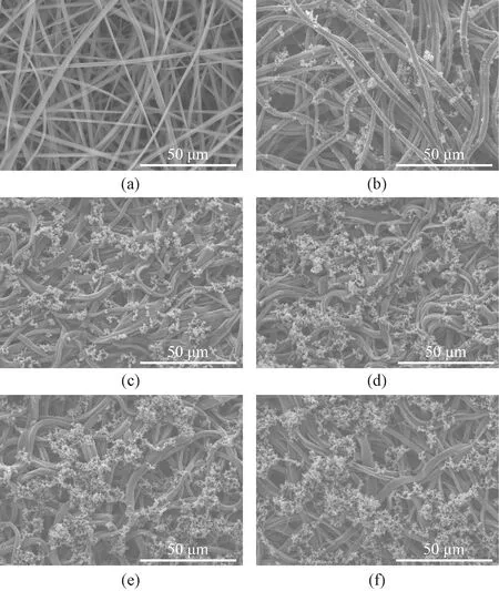
Fig.2 SEM images of ZE fiber mat and PPy/ZE fiber mats with different treatment durations:(a) ZE; (b) PPy/ZE-2 h; (c) PPy/ZE-4 h; (d) PPy/ZE-6 h; (e) PPy/ZE-8 h; (f) PPy/ZE-10 h
2.2 Mechanical properties
As shown in Fig.3, the breaking stress of the ZE fiber mat in dry state (ZE-dry) was 0.91 MPa and the yield point was achieved at a low strain of only 4.43%. The breaking process of the mat displayed an obvious fracture heterogeneity. This was probably due to the loose fibrous structure. The maximum strain was about 116%. Once wetted, the ZE fiber mat in wet state (ZE-wet) showed a dramatically elevated stretchability with a maximum strain of 202%. The invaded water molecules served as the plasticizer which broke the hydrogen bonds and van der Waals force to allow the movement among polymers and generated a substantial increase in elongation[18]. However, the breaking stress did not change much (0.80 MPa), which proved the effective cross-linking between the zein proteins and the epoxy GTE. The fracture of the mat was sharp with no heterogeneity. This was probably due to the cross-linked structure at the polymer level and the enhanced interaction among the wetted fibers.
After eight hours of PPy modification, the breaking stress of PPy/ZE fiber mat in the dry state (PPy/ZE-8 h-dry) increased by 263% to 3.3 MPa, and a sharp break was observed at a low strain of 40.1%. The PPy/ZE-8 h fiber mat became stronger but more rigid in the dry state. Since the tensile strength of PPy film could reach 8 MPa or higher while the elongation is 2%-8%[19], this result implied that the fibers had a core-shell structure in which the PPy coating with limited stretchability restricted the extension of zein fibers but increased the breaking stress. In addition, the fibers fused by water might elevate rigidity and the more compacted structure of the fiber mat elicited a reduction in elongation and a rise in stress. In the wet state, the strain of the PPy/ZE-8 h fiber mat (PPy/ZE-8 h-wet) could be raised to 83.0% and the stress was weakened to 1.40 MPa. Moderate elongation and stress allow the PPy/ZE-8 h fiber mat to be used in a variety of applications[20-21].

Fig.3 Stress-strain curves of ZE fiber mat and PPy/ZE-8 h fiber mat in dry and wet states
2.3 Conductivity
During the polymerization of pyrrole, the oligomers containing initiators were first generated in water, and these oligomers were physically adsorbed onto the surface of the microfiber by hydrogen bonding. Since the oxidation potential of these oligomers adsorbed on the fiber surfaces was lower than that of the pyrrole in the solution, reactions occurred mainly on the surface rather than in the aqueous solution[22]. By prolonging the reaction duration from 2 h to 8 h, more pyrrole molecules were polymerized on the surface of fibers,which formed more integrated and thicker PPy layers. The thicker PPy layers provided a more efficient conductive network and elevated the conductivityσof PPy/ZE fiber mats from 175.07 S·m-1to 398.17 S·m-1as shown in Table 1. The further reaction did not elicit a substantial increment in conductivity, which showed a similar trend like morphological properties.

Table 1 Conductivities of PPy/ZE fiber mats with different treatment durations
2.4 EMI shielding performance
The EMI shielding performances of PPy/ZE fiber mats at X-band (8.5-12.0 GHz) are shown in Table 2. For each sample modified for a treatment duration, the total EMI shielding efficiency at frequenciesfin X-band was close, and thus an average value of total EMI shielding efficiencyE(dB) was given for each sample. With the increase in the reaction time from 2 h to 8 h,Eelevated gradually from 12.41 dB to 26.67 dB. Further extension in treatment time to 10 h did not shift it much. This trend was similar to the changes in conductivity shown in Table 1.
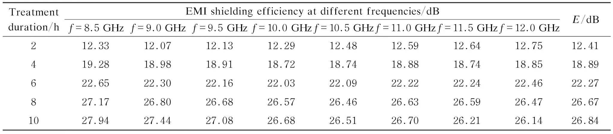
Table 2 EMI shielding performances at X-band (8.5-12.0 GHz) of PPy/ZE fiber mats with different treatment durations
The relationship between the conductivity of PPy/ZE fiber mats andEis displayed in Fig.4. It showed a non-linear correlation with a reducing slope.
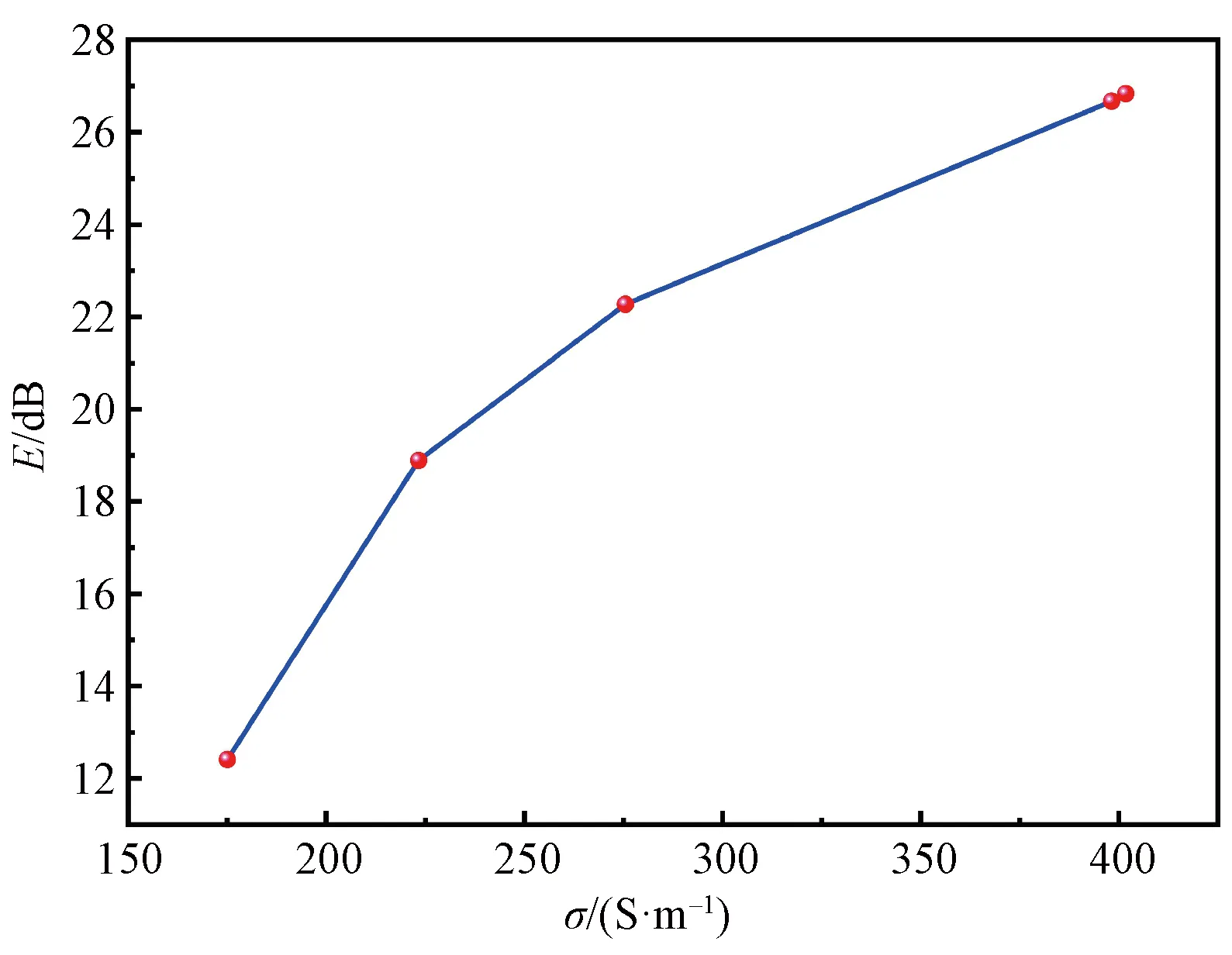
Fig.4 Effect of conductivity of PPy/ZE fiber mats on E
According to the above results, the fiber mats of PPy/ZE-2 h and PPy/ZE-4 h could shield at least 94.2% of the EMW, while the samples PPy/ZE-6 h and PPy/ZE-8 h were able to block 99.4% and 99.8% of the EMW, respectively. The requirement for the commercial EMI shielding materials is at least 20 dB,i.e., 99% of the EMW[23-24], and thus the PPy/ZE fiber mats with treatment duration above 6 h in this work can meet the requirement for applications.
To compare the EMI shielding performance with other works, the average total EMI shielding efficiency per thickness of the PPy/ZE fiber mats was calculated and exhibited in Table 3. The calculation formula is
(1)
whereIis the average total EMI shielding efficiency per thickness (dB·mm-1), anddis the thickness of samples (mm).

Table 3 Comparison of the I of PPy/ZE fiber mats and the PPy modified EMI shielding materials reported by other works
TheIof the PPy/ZE-10 h fiber mat was about 1.5-4.5 times of the EMI shielding materials composed with PPy reported in Refs.[25-27]. There were mainly three possible reasons. Firstly, the PPy conductive layer was constructed on the top layer of fibers with a strong affinity to the protein base. The integrated conductive network provided the PPy/ZE fiber mats with a high conductivity which was important to generate the reflective shielding effect. Secondly, the fibers were composed of the outer layer PPy and the inner core ZE fiber and formed a core-shell heterostructure. The interface of the core and the shell could serve as a “capacitor” due to the dielectric polarization and accumulate charges to induce weakening of the EMW. Finally, the ultrafine fibrous structure of the PPy/ZE fiber mats and PPy nanoparticles constructed a complicated porous architecture with a large surface area for the EMW multi-reflection inside the mat and the EMW absorption.
Considering flexibility, lightness, biocompatibility, and effective shielding performance, the PPy/ZE fiber mats can be used in various applications as shown in Fig.5, such as wearable electronic devices, aviation, space flight, military, electronics and in vivo and in vitro medical devices. After use, the products can be degraded in water, soil, or in the body because of the inherent biodegradability of the protein-based fiber mats.

Fig.5 Possible applications of PPy/ZE fiber mats
3 Conclusions
In summary, this work provided a series of biobased PPy/ZE fiber mats for the EMI shielding via simple cross-linking andin-situpolymerization approaches. The porous and fibrous structure was maintained after the PPy coating. In addition, the stress of the PPy/ZE fiber mats was substantially enhanced, while the strain was dramatically reduced compared with that of the ZE fiber mat. By prolonging the treatment duration, the conductivity of the PPy/ZE fiber mats was improved up to 401.76 S·m-1and the average total EMI shielding efficiency per thickness was elevated up to 89 dB·mm-1, which met the requirement, for instance, aircraft and space suits. This work demonstrates a green and simple fabrication method for the production of thin and lightweight biobased EMI shielding mats, which may be a promising strategy for the mass production of EMI shielding materials to address EMI problems in multiple fields.
杂志排行

Journal of Donghua University(English Edition)的其它文章
- Image Retrieval with Text Manipulation by Local Feature Modification
- Multi-style Chord Music Generation Based on Artificial Neural Network
- Design of Rehabilitation Training Device for Finger-Tapping Movement Based on Trajectory Extraction Experiment
- High-Efficiency Rectifier for Wireless Energy Harvesting Based on Double Branch Structure
- Review on Development of Pressure Injury Prevention Fabric
- N-gamboyl Gemcitabine Inhibits Tumor Cells Proliferation and Migration