An Integrated Structure Analysis Method of Active Surface Antenna by Using the Simplified Actuator
2023-09-03YouBanPeiyuanChaiQianXuandShufeiFeng
You Ban ,Peiyuan Chai ,Qian Xu ,and Shufei Feng
1 School of Mechanical Engineering,Xinjiang University,Urumqi 830017,China;banyou_xd@163.com
2 Xinjiang Astronomical Observatory,Chinese Academy of Sciences,Urumqi 830011,China
3 School of Mechanical Engineering,Dongguan University of Technology,Dongguan 523808,China
Abstract The main surface of a large reflector antenna is composed of thousands of panels,which are inevitably deformed under natural load,leading to a great deterioration of electrical performance of the antenna.The active surface technique is an effective method to compensate antenna deformation error and has been widely used.The actuator is a complex component,it has not been established in the antenna structure analysis model,which limits the theoretical analysis ability of the active surface technology.To solve this problem,an integrated structure analysis method of active surface antenna by using the simplified actuator is proposed.First,according to the supporting characteristics and adjusting function of the actuator,the complex actuator is simplified a simple structure of support beams,support truss and adjustment beam.Second,the finite element model of the active surface antenna including the simplified actuator is established.Then,the relationship between the adjustment value (load) of adjustment beam and the deformation of the antenna structure is deduced,and the integrated analysis method for realizing the active adjustment of panels is established.Finally,the model and adjustment analysis method of the active surface antenna in this paper is applied to an 8 m antenna,and satisfactory structural analysis results are obtained,which shows the effectiveness and universality of the method,and provides a reference for the modeling and adjustment analysis of the active surface antenna.
Key words: methods: numerical–telescopes–methods: analytical
1.Introduction
With the development of deep space exploration,radio astronomy and other fields,reflector antenna has been developing toward the direction of large aperture,high precision and high frequency (Baars &Kärcher 2018).The antenna will inevitably be affected by gravity,wind,temperature and other natural loads,the reflector will be deformed,the accuracy will be poor,leading to a significant decline in performance (Hoerner &Wong 1975).For the high-precision large reflector antenna with tens of meters of aperture,thousands of panels and thousands of tons of weight,it is difficult to achieve the accuracy index of millimeter or even sub-millimeter in its surface.In order to meet the accuracy of reflector,active surface technique is used to compensate the surface error of antenna and it is widely used in large reflector antennas with surface accuracy of millimeter or sub-millimeter(Wang et al.2018),Examples include 100 m Green Bank Telescope (GBT) in the United States (Richard 1998),64 m Sardinia Radio Telescope (SRT) in Italy (Orfei et al.2004),50 m Large Millimeter Telescope (LMT) in Mexico (Hughes et al.2010),and 65 m Tianma Radio Telescope (TMT) in Shanghai (Dong et al.2016).Active surface technology will also be used in the near future by the Xinjiang 110 m Qitai radio Telescope (QTT) (Wang 2014),which will be becoming the world’s largest fully steerable radio telescope.As shown in Figure 1,a panel is supported by four actuators and adjusted to the locations of the ideal reflector or best fitting reflector.Therefore,accurate calculation of antenna deformation and active surface analysis are important problems.

Figure 1.Active surface of an antenna.
Using the active surface technology to adjust the panels to designated locations has been discussed in many papers.Lian et al.(2021) gave the approximate relationship between the adjustment value and the elastic deformation of the panel.However,when the adjustment value is larger,the deformation error of the panel is also larger.Fu et al.(2015) put forward the calculation method about the ideal reflector and best fitting reflector with two parameters,five parameters and six parameters,and calculated the adjustment value of the main reflector and the sub-reflector after the gravity deformation of the large Cassegrain antenna structure.Wang et al.(2008) gave the influence relation matrix between the target point and the adjustment amount,and received satisfactory results.For Wang et al.(2017),according to the initial position of the actuator and the relationship between the adjustment point and the target point,a new mathematical model and program for directly calculating the motion of the actuator were established.Sun et al.(2021)provided a calculation method to adjust the reflector surface through the aperture phase profile.The adjustment values are calculated through the fitting surface,and the surface accuracy of the 65 m antenna is reduced from 0.28 to 0.19 mm.In (Wang et al.2021),the distribution of actuators and the design method of panels were studied,and the methods of triangular panels,node index and the fitting solution method of a single panel are given.This method provides a reference for the design and realization of the active surface or deformable sub-reflector for high performance large radio telescopes.Although many scholars have studied the active surface compensation technology,the calculation of active adjustment is based on the separation of actuator and panel,without considering the influence of the overall antenna structure on panel adjustment,which will limit the theoretical analysis ability of active surface technology.
To solve this problem,an integrated structure analysis method of active surface antenna by using the simplified actuator is proposed in this paper.First,the complex structure of the actuator is simplified according to its supporting characteristics and adjusting functions.Second,the finite element model of the active surface antenna including the simplified actuator is established,and the simulation method of the actuator active adjustment panel is proposed,and the relationship between the adjustment value and the antenna structure deformation is given.Finally,this method is applied to the 8 m antenna,and good analysis results are obtained.The results show that the method is effective and universal,which provides a theoretical reference for modeling and active adjustment analysis of active surface antenna.
2.Integrated Structure Analysis for Active Surface Antenna
In this section,the finite element model of active surface antenna by using the simplified actuator and the realization method of adjustment the panel are introduced.
2.1.The Simplified Actuator
Because the actuators used by GBT (Richard 1998),SRT(Orfei et al.2004),LMT (Magaña et al.2014) and TMT(Wang 2010;Dong et al.2016) have complex and different structures,they should be simplified and the functions and characteristics of actual actuators should be realized in simulation.The actuator is a complex mechanism.It converts the rotating motion of the motor into the linear motion of the screw through worm gear,ball screw and other transmission parts.The screws support the panels and adjust to the specified position.The motion essence of the actuator is linear motion,and its motor and transmission part can be used as the input part of the actuator.In the simplified model,they are the loads that control the adjustment value of the actuator.
The linear motion of a screw can be analyzed by means of a rod or beam.Because the antenna works under different working conditions,the actuator will be affected by bending moment,torque or shear,it is better to use the beam to simulate the linear motion of the screw.Typically,one actuator is connected to the corners of four adjacent panels,so that the actuator has four support beams that move in sync.To achieve this,four beams need to be connected with support trusses,and an adjustment beam is attached below the support trusses and acts as a component to achieve the adjustment function,as shown in Figure 2.In order to facilitate the connection and calculation in the finite element model,the beam element is also used to analyze the support truss.
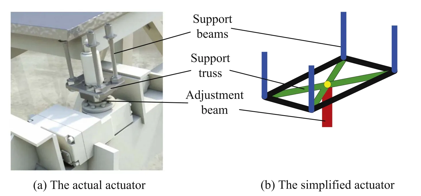
Figure 2.Correspondence between actual actuator and the simplified actuator.
In the early studies on the active surface,the panel was not built on the antenna model,but the deformation of the Backup structure(BUS) was equivalent to the panel deformation (Stutzki et al.2008).Later,the panel is installed on the upper node of the BUS.Because the surface of the antenna is composed of panels,the adjacent four panels connected to a BUS upper node.In order to avoid the panel being squeezed,the adjacent panel needs to retain a gap,so the designer uses four short beams to connect the upper node of the BUS and four adjacent panels(Lian et al.2022)(see Figure 3).However,these short beams are relatively inclined and cannot be adjusted.The simplified actuator model proposed in this paper can solve this problem to some extent.
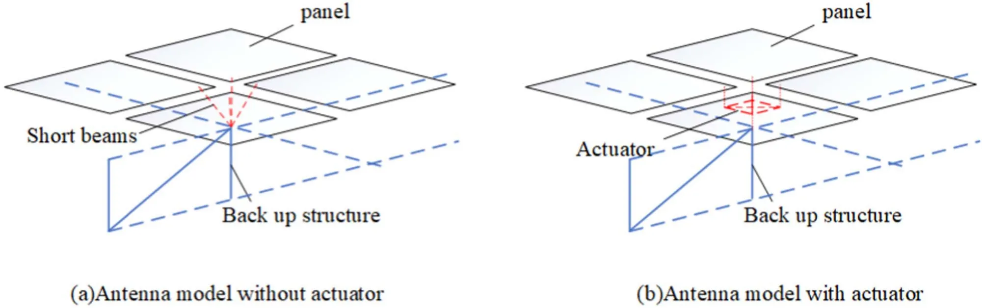
Figure 3.The comparison of the finite element model with and without the actuator.
2.2.Structural Calculation Method of Active Surface Antenna Model
A finite element model of an active surface antenna is established,including a BUS,actuators and panels.The simplified model of the actuator consists of four support beams,a support truss and an adjustment beam.The BUS is a space truss,usually simulated using beam elements.Because of the elastic deformation of the panel,shell element is more suitable for simulation.
In order to calculate the deformation of the antenna structure,the stiffness equation should be established:
whereKis the stiffness matrix,uis the node displacement vector,andPis the node load vector.The stiffness matrixKis formed by the combination of two elements according to their joint order.The calculation methods of beam element and shell element are described below.
The beam element can not only bear axial force and bending moment,but also bear torque.The space beam element has two nodesiandj,and each node has 6 degrees of freedom.
The stiffness matrix of axial displacement is similar to that of rod element:
whereEis Young’s modulus,Aijis the cross-sectional area andlijis the length.
When the beam is subjected to torsion,the torsion angle is similar to the axial displacement of the rod,and the stiffness matrix of the similar rod element is obtained:
whereGis shear modulus andJis rotational moment of inertia.
When the beam is bent in the plane,the corresponding stiffness matrix is:
whereIijZandIijYare moments of inertia.
The above stiffness matrices are combined in the order of degrees of freedom to obtain the complete element stiffness matrix in the local coordinate systemKbeam:
The shell element consists of a membrane element and a bending element,and the element has 6 degrees of freedom on the node.In order to calculate accurately,the triangular shell element is used to simulate the elastic deformation of the panel.
Triangular bending element consists of discrete Kirchhoff theory (DKT) element (Batoz et al.1980),whose stiffness matrix is:
whereDis the elastic coefficient matrix,Bis the straindisplacement matrix,ξ and η represent the components of the area coordinates.KDKTwas obtained by the three-point Gaussian integral method.
The improved membrane element with Allman degree of freedom can analyze large deformation (Cook 1986),and its stiffness matrix is:
whereKLSTis the stiffness matrix of the linear strain triangle element,andTis a transformation matrix,it convertsKLSTtoKallman(Cook 1986).
There have redundant zero-energy modes in this element,so define a penalty stiffness (Macneal &Harder 1988):
where δ is the penalty parameter(0.01),Vis the volume andQis the relative rotation matrix.
By addingKallmanandKs,a membrane element without defects is obtained,whose stiffness matrix is:
The stiffness matrix of shell element in local coordinate system is obtained by combining membrane element and bending element in order of freedom.
The above two types of elements are calculated in the local coordinate system,which needs to be converted to the global coordinate system to calculate the stiffness matrix.These stiffness matrices were combined according to the order of degrees of freedom of nodes to obtain the stiffness matrixK.
The equivalent node loadPis calculated based on the given environmental load and mesh shape.The above stiffness matrixKand node load vectorPare substituted into Equation (1) to obtain all node displacementsuof the antenna.
2.3.The Realization Method of the Simplified Actuator Adjustment the Panel
Figure 4 is a schematic diagram of the simplified actuator active adjustment.An equal and opposite load is applied to both ends of the adjustment beam to stretch or shorten it,causing the support truss and the support beams to displace along the axis,and the panel is adjusted.The model simulates the motion and force of the actual actuator.
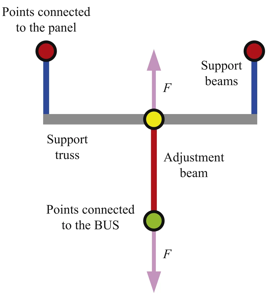
Figure 4.Schematic diagram of the simplified actuator.
According to Equation(1)and Figure 4,the upper and lower nodes of the adjustment beams transform in Equation (1),and the load is applied.The calculation method of active adjustment model of reflector antenna is obtained:
whereKoo,Kod,Kouare the stiffness matrix of other nodes except the adjustment beams,uupis the displacement vector of the upper nodes of the adjustment beams,udownis the displacement vector about the lower nodes about the adjustment beams,uotheris the displacement vector about the other nodes.PdownandPupare the equivalent environmental load(gravity load) about the upper and lower nodes of the adjustment respectively,Fis the load applied,FdownandFupare equal and opposite load.
In Equation (16),the actuator adjustment values can be converted into node displacement inputuupandFis the unknown external loads.Since the adjustment beam has only two nodes,the number ofuupandudownis the same,and the unknown quantity is balanced with the number of equations,with a unique solution.
It can be obtained from Equation (16) that:
The expression ofuotheraboutuupandudowncan be obtained from Equation (18) and Equation (19):
The expression ofudownaboutuupcan be obtained from Equation (17) and Equation (20):
Substitute Equation (21) into Equation (17) to get an expression:
Since the stiffness matrix is only related to node coordinates,sufficient conditions are available to solve:
Finally,by substitutingFfinto Equation (16),the relationship between the adjustment values and the antenna structure can be obtained,and the antenna structure deformation after active adjustment can be accurately analyzed.
3.Numerical Results and Discussion
In this section,the method of the second section is used to calculate the gravity deformation and adjust the panel for the 8-meter antenna,and the effectiveness of the method is verified.
3.1.The 8 m Antenna Model
In order to evaluate the feasibility of this method,a case of a reflector antenna with a diameter of 8 m and a focal length of 3 m is carried out.Figure 5 is a quarter diagram of the BUS.The BUS is steel structure with a circular cross-section.The 36 panels form a standard paraboloid with a thickness of 20 mm.

Figure 5.Quarter diagram of the BUS.
Figure 6 shows the finite element model of the antenna.The three-ring panels are evenly distributed along the circumference,and 48 actuators are distributed in the upper node of the BUS.The panels have little influence on the structural deformation of the whole antenna (Stutzki et al.2008),and the stiffness of the panel is a small value in the simulation.In order to make the deformation of the panel reasonable,its mass is equivalent to giving four actuators,and the mass of the panel is zero.The elastic deformation of the panel is mainly affected by the BUS and the actuator.
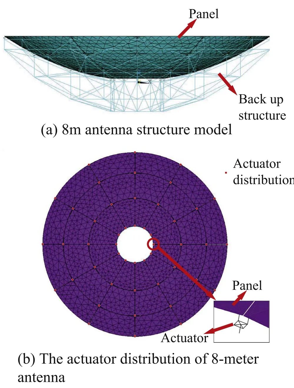
Figure 6.Finite element model of 8 m antenna.
3.2.The Calculation Result of Gravity Deformation
The gravity deformation of the 8 m antenna finite element model with and without the actuator needs to be compared.In order to compare the results accurately,the weight of the actuator and the small short beam is zero.The results show that the actuator structure has little influence on the antenna deformation,as shown in Figure 7.
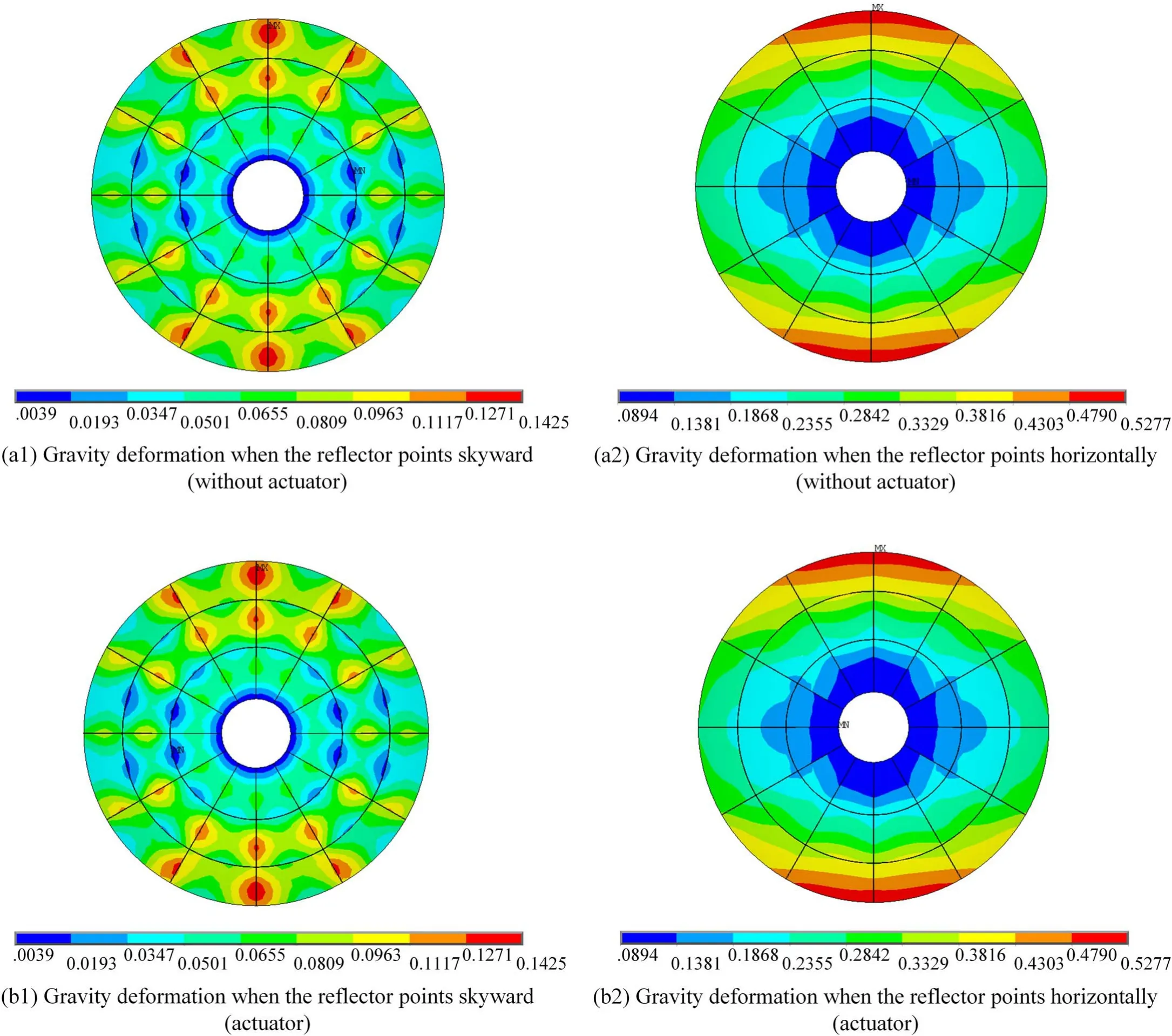
Figure 7.The gravity deformation comparison of the 8 m antenna with and without the actuator when the reflector points skyward and horizontally (unit: mm).
Before calculating the active adjustment simulation analysis,the stiffness Equation (1) of the finite element model needs to be verified.Figure 8 shows the gravity deformation of the 8 m antenna (The actuator has a normal weight) when it pointing skywards and horizontally.According to the grid division,elements information (nodes composition,nodes number and nodes coordinates) was obtained,and the equivalent load of nodes was calculated,and stiffness matrix and load vector were obtained.Equation (1) is solved and compared with the calculation results of the finite element software.As shown in Table 1,the maximum displacement error of all nodes of the antenna is 7.9×10⁻⁸mm when the antenna points skywards and 4.1×10⁻⁷mm in when the antenna points horizontally.The results show that Equation(1)can accurately calculate the gravity deformation of 8 m antenna,which lays a foundation for the calculation of subsequent active adjustment of panel deformation.
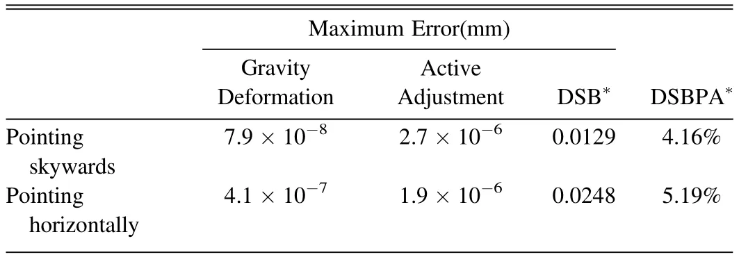
Table 1Maximum Node Displacement Error of the Antenna before and after Adjusting the Panel
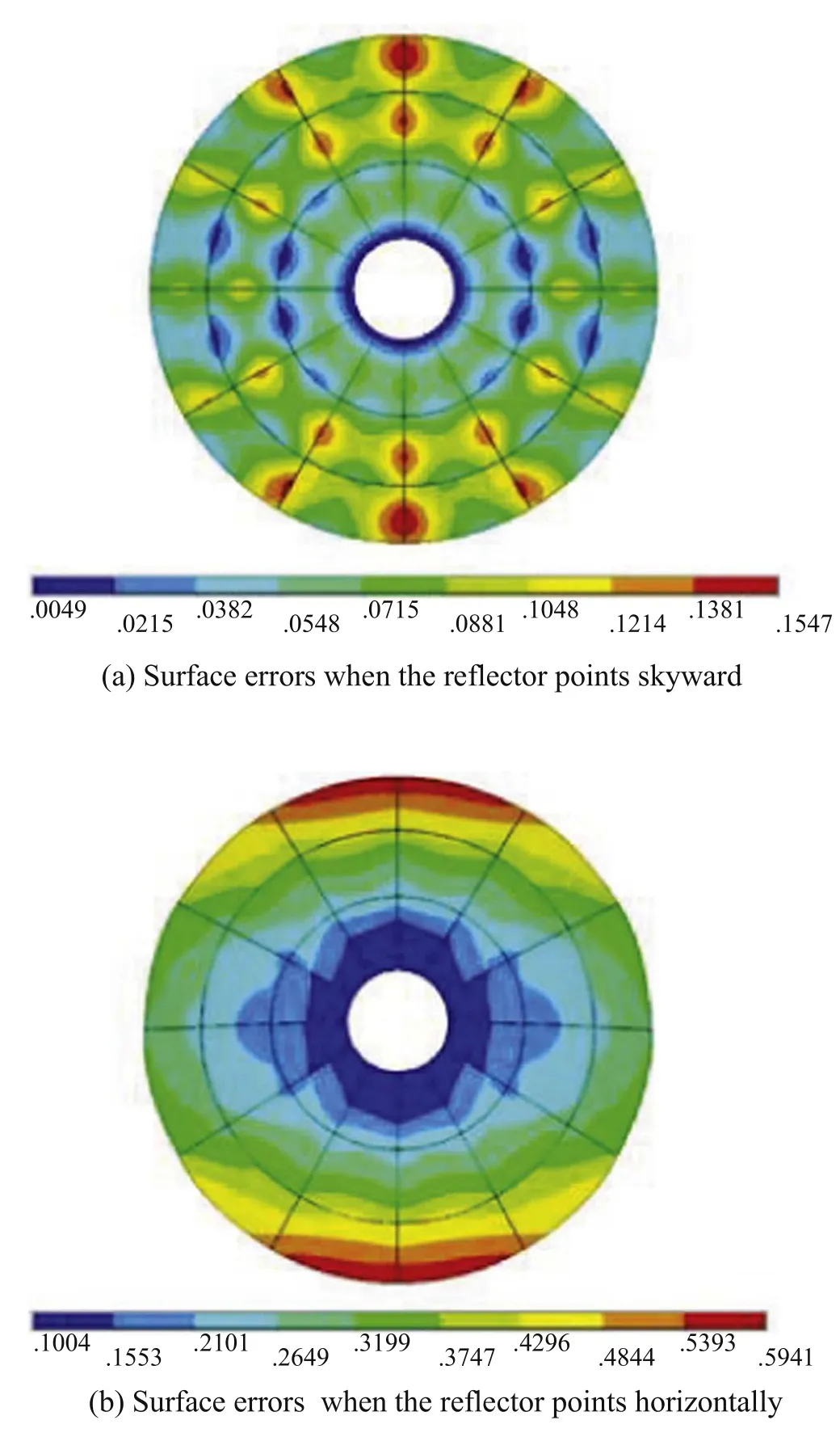
Figure 8.Surface errors of 8 m antenna (unit mm).
3.3.The Calculation Result of Adjustment the Panel
In this paper,the ideal antenna structure was used to calculate the active adjustment model,and 48 actuators have 48 randomly adjustment values(5 mm),as shown in Figure 9.The adjustment value are converted into node displacement and substituted into Equation(23).The load is calculated and input into the finite element model to make the adjustment beam extend or shorten along the direction of the actuator,so as to achieve the function of adjusting the panel.It is worth mentioning that when the antenna is deformed by gravity,the direction of the actuators will change slightly,so the actuator should adjust the panel in the true direction.On the other hand,the adjustment beam can extension or shorten by the adjustment value,and the adjustment value reflects the displacement of the node connects panel and actuator (The node is on the support beam),so the node displacement of the support beam should be consistent with the adjustment beam.
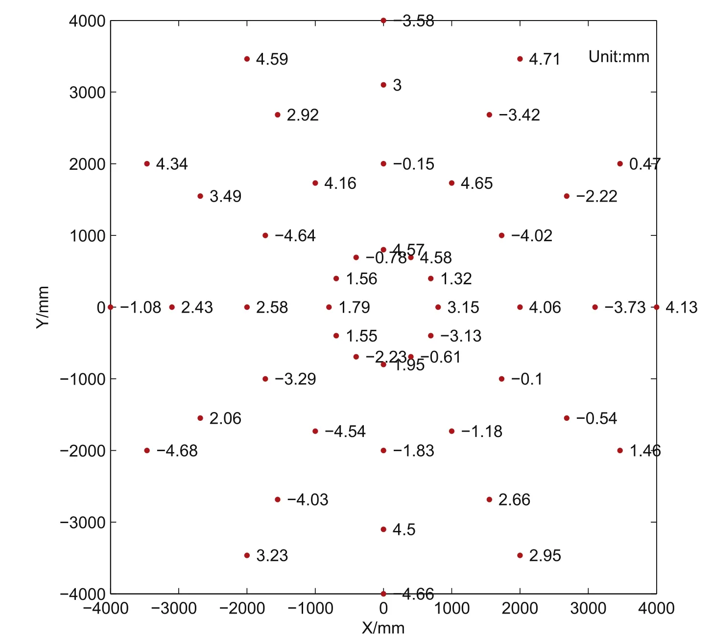
Figure 9.Randomly adjustment values.
According to Figure 9,the same adjustment value is given to two conditions respectively,and the deformation of the panel after active adjustment is shown in Figure 10.Table 1 shows the maximum displacement error of each antenna node before and after active adjustment.When loading is applied,the maximum node displacement errors of the proposed method and the finite element software are 2.7×10⁻⁶mm and 1.9×10⁻⁶mm respectively,which meet the requirements of analysis accuracy.The maximum node displacement errors of the support beams are 0.0129 and 0.0248 mm,but the maximum relative adjustment value errors are only 4.16%and 5.19%.Because the structure is not completely rigid,the node displacement of the support beam has some error,but the maximum of this error is acceptable.The optimization of the simplified actuator structure and the influence of actuator pointing change on adjusting panel must be carried out in the follow-up work.In addition,the random adjustment value can cause the panel to be squeezed or stretched to an unreasonable shape,which can be avoided when calculating the adjustment value of the best fitting paraboloid.
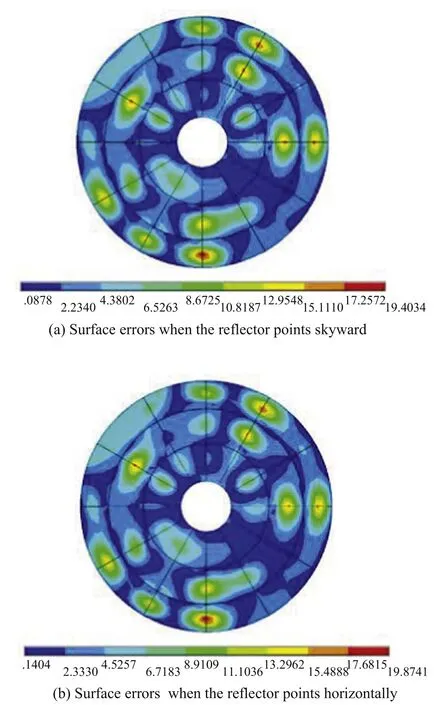
Figure 10.Deformation of the panel after adjustment (unit mm).
4.Conclusion
In this paper,an integrated structure analysis method of active surface antenna by using the simplified actuator is proposed.This method can realize the simulation analysis of antenna including actuator,including establishing the stiffness equation of finite element model,and deducing the calculation formula of the actuator adjustment value and antenna structure deformation.The results show that the method is correct and effective.Through case analysis,a good accuracy of antenna structure analysis was obtained,and the subsequent work to be improved was defined,such as optimizing the actuator structure and the effect on adjusting panel when the actuator direction change.In the future,the optimized actuator model will be used to adjust the panel and a surface data will be given when the surface is adjusted to the best fit paraboloid.
Finally,this method has reference value for modeling and adjustment analysis of active surface antenna.
Acknowledgments
This work was supported by the National Key Research and Development Program of China (Nos.2021YFC2203501 and 2021YFC2203601),the National Natural Science Foundation of China (No.52165053),the China Postdoctoral Science Foundation (2021M702751),the Tianshan Young Talent Project of Xinjiang (2020Q068) and the Doctor Scientific Research Project of Xinjiang.
ORCID iDs
杂志排行

Research in Astronomy and Astrophysics的其它文章
- Unveiling the Initial Conditions of Open Star Cluster Formation
- The Spin Measurement of MAXI J0637-430: a Black Hole Candidate with High Disk Density
- The Chromatic Point-spread Function of Weak Lensing Measurement in the Chinese Space Station Survey Telescope
- Evaluation of Coronal and Interplanetary Magnetic Field Extrapolation Using PSP Solar Wind Observation
- Sodium Abundances in Very Metal-poor Stars
- Speckle-interferometric Study of Close Visual Binary System HIP 11253(HD 14874) using Gaia (DR2 and EDR3)