Improved lazy theta* algorithm based on octree map for path planning of UAV
2023-05-31MengshunYuanTongleZhouMouChen
Meng-shun Yuan,Tong-le Zhou,Mou Chen
College of Automation Engineering, Nanjing University of Aeronautics and Astronautics, Nanjing, 211106, China
Keywords: Unmanned aerial vehicle Path planning Lazy theta* algorithm Octree map Line-of-sight algorithm
ABSTRACT This paper investigates the path planning method of unmanned aerial vehicle (UAV) in threedimensional map.Firstly,in order to keep a safe distance between UAV and obstacles,the obstacle grid in the map is expanded.By using the data structure of octree,the octree map is constructed,and the search nodes is significantly reduced.Then,the lazy theta* algorithm,including neighbor node search,line-of-sight algorithm and heuristics weight adjustment is improved.In the process of node search,UAV constraint conditions are considered to ensure the planned path is actually flyable.The redundant nodes are reduced by the line-of-sight algorithm through judging whether visible between two nodes.Heuristic weight adjustment strategy is employed to control the precision and speed of search.Finally,the simulation results show that the improved lazy theta* algorithm is suitable for path planning of UAV in complex environment with multi-constraints.The effectiveness and flight ability of the algorithm are verified by comparing experiments and real flight.
1.Introduction
With the development of UAV technology,UAV has been applied in many fields.In the field of national defence,Military UAV can accomplish tasks such as intelligence reconnaissance,signal transmission,electronic countermeasure,target hitting and target aircraft [1].Path planning is an indispensable part of the UAV mission planning system,which can significantly improve the operational capability of military UAV,so it has been widely concerned in recent years and has become a research hotspot of military UAV technology [2].In path planning,the algorithm needs to plan a reasonable flight path for UAV from the starting point to the ending point in the given map[3].The path should meet the safety,rapidity and the corresponding constraints [4].Thus the path planning has always been the research hot topic of intelligent control and decision making for UAV.
The first step of path planning is to build the map,and the classical method is grid map modeling.In Refs.[5,6],the regular grid map was used for its simplicity and convenience.In threedimensional map,the number of path nodes in regular grid maps is huge,and the search algorithm takes a long time to run.In Ref.[7],based on the octree data structure,the octree map significantly reduced the number of map path nodes,shorten the search time,and achieve better results.When the UAV is flying,it not only needs to consider the performance limitations of UAV,but also needs to consider the constraints of threat area,such as no fly zone.In Refs.[8-10],these methods translate avoiding threat zones and no-fly zones into geometric calculations that allow the UAV to eventually reach the target position.At the same time,there exists an obstacle edge collision problem in the grid map [11].Thus,it is necessary to expand the obstacles so that the UAV can keep a safe distance from the obstacles.
After the completion of map modeling,path planning should be carried out [12].In three-dimensional path planning,some works can be found in the literature.In Ref.[13],an improved ant colony(ACO) algorithm was used in path planning.Focusing on the path planning problem of UAV,an improved particle swarm optimization (PSO) algorithm was proposed to plan path in Ref.[14].Improved Rapidly-Exploring Random Tree (RRT) algorithm has strong randomness and can quickly obtain the feasible path,but it can't obtain the optimized path [15,16].Heuristic algorithm is a series of algorithms derived from A*algorithm[17].In Ref.[18],the modified A*algorithm was based on the cost function and was used to solve the three dimensional path planning problem.In Ref.[19],the Theta*algorithm was proposed based on A*algorithm to solve the any angle path planning problem.In Ref.[20],the lazy theta*algorithm was applied to the grid map to plan the path.The planned path of lazy theta* algorithm not only has fewer nodes and shorter search time,but also is smooth,which is beneficial for the UAV to fly along the path.Based on the above research results,in order to quickly plan a safe,smooth and low-cost path [21],an optimization algorithm is proposed by combining octree map with lazy theta* algorithm.
This paper is organized as follows.Firstly,problem description of the path planning problem is given,including four parts: UAV constraints,obstacle expansion,the octree map and neighbor node search.Then,the flow of the algorithm is described in detail.This algorithm first performs obstacle grid expansion on the original map information,then builds the octree map,and then uses the improved lazy theta* algorithm to plan path,which improves the neighbor node search,line-of-sight algorithm and heuristic weight adjustment.Finally,the simulation results are given to show the planned path which can meet the requirements.
2.Problem statement
The path planning problem of UAV can be transformed into an optimization problem with multiple constraints[22].The planning space is a three-dimensional grid map,and each grid is a search node.Therefore,the problem of path planning [23]can be described as: under the premise of satisfying the constraint conditions,the continuous path nodes are selected from the grid map nodes,so that the UAV has the minimum path cost when flying along the path nodes[24].
2.1. UAV constraint and threat area constraint
To guarantee that the planning path is actually flyable,it is necessary to consider UAV maneuverability,terrain,threat and other constraints [25].
(1) Maximum yaw angle constraint:Due to the limitation of UAV maneuverability,the planned yaw angle should be less than the maximum yaw angle [26]as shown in Fig.1.The maximum yaw angle constraint can be expressed as
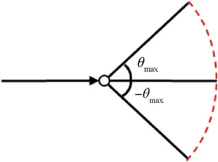
Fig.1.Maximum yaw angle constraint.
where,θirepresents the yaw angle at path point of sectioni,and θmaxrepresents the maximum yaw angle.
(2) Maximum pitch angle constraint: Due to the influence of UAV thrust,gravity and other factors,there is a certain limit value of UAV's pitching ability [27].The maximum pitch angle constraint can be expressed as
where,φirepresents the pitch angle at path point of sectioni,and φmaxrepresents the maximum pitch angle of the UAV.
(3) Minimum path segment length constraint: Limited by the maneuverability of UAV,the UAV must guarantee a shortest straight-line flight distance before changing its course[28]as shown in Fig.2.The minimum path segment length constraint can be expressed as
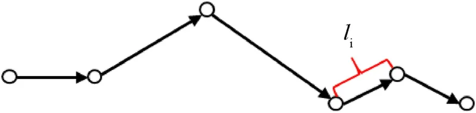
Fig.2.Path segment length.
where,lirepresents the path length of sectioni,andlminrepresents the shortest direct flight distance of UAV.
(4) Minimum relative height constraint: In order to ensure the flight safety,the UAV needs to keep a certain relative safe distance from the ground during the flight as shown in Fig.3.The minimum relative height constraint can be expressed as

Fig.3.Minimum relative height constraint.
where,zrepresents the altitude of the current path point,hminrepresents the minimum relative height,andhTindicates the terrain altitude directly below the UAV.
(5) Threat area constraint:In order to ensure flight safety,UAV is required to be located outside the threat area at any time[29].The model of threat area needs to be built on the specific situation of threat objects [30],generally including sphere,cylinder,etc.Fig.4 shows the cylindrical threat zone,indicating the threat of the no fly zone.
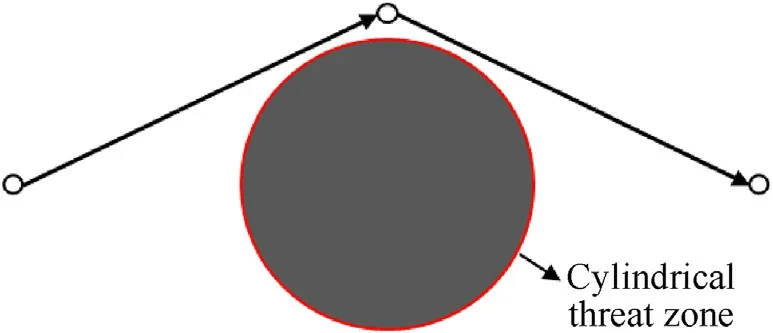
Fig.4.No fly zone constraint.
2.2. Obstacle grid expansion
The path searched directly in the grid map may collide with the edge of the obstacle grid[31].Fig.5 shows the collision problem of the grid edge in the two-dimensional map.This problem also exists in three-dimensional map.In order to ensure the safety of UAV flight path,it is necessary to deal with the edge of obstacles.
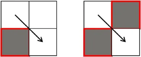
Fig.5.Edge collision problem.
The obstacles expansion method is used to expand the obstacles in the initial map.Based on the obstacles,a certain area around the obstacles is set as the obstacle area.Hence,the corresponding expansion range can be set according to the threat degree of the obstacles.After obtaining the processed map data,the octree map is constructed.The new map can keep a safe distance between UAV and obstacles in flight.
2.3. Octree map model
Octree map has been studied in the map model,which is established based on the data structure of octree.The octree map schematic diagram is shown in Fig.6.The process of building octree map is to divide the big cube into eight pieces until it becomes the minimum grid.Furthermore,the size of the minimum grid can be set.Generally,the smaller map grid indicates the higher search accuracy.In the data structure of octree,the whole big cube is the root node,and the smallest block is the leaf node.In the octree map,the volume of the upper node is eight times of that of the lower node.
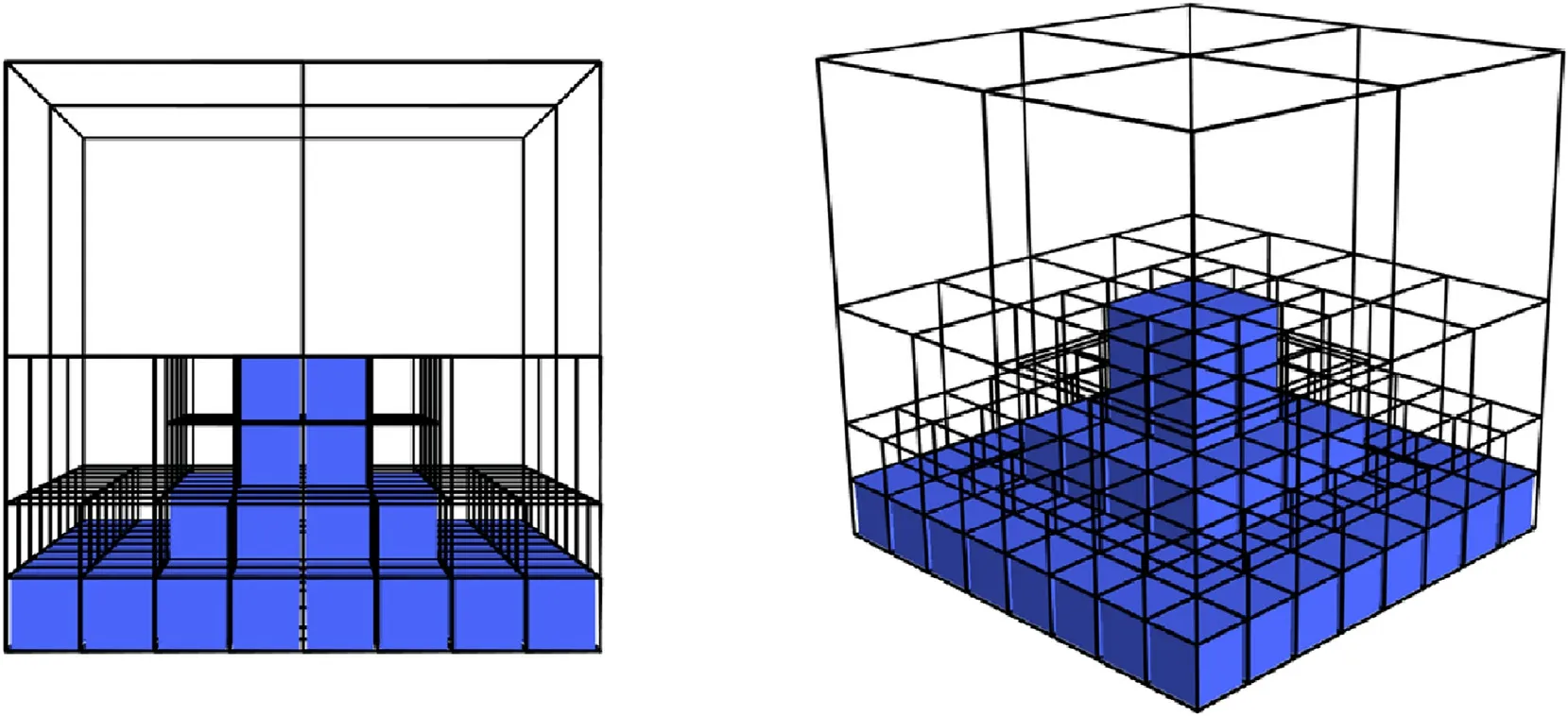
Fig.6.Octree map schematic diagram.
In octree map,nodes store their own information,including coordinate,size and state.When there is no obstacle in the grid,it is marked as free grid,otherwise it is marked as obstacle grid.Octree map is different from the traditional grid.When all the child nodes of a node are in the same state,it is not necessary to expand this node.In the process of map construction,the grid will be automatically divided into smaller grids in the area with dense obstacles.Therefore,in octree map,the size of grid is different and the number of nodes is small.These advantages are conducive to the subsequent path planning.
2.4. Neighbor node search
This paper builds an octree map,so the neighbor node search method in the algorithm needs to be changed.Obtaining a neighbor node set is divided into four steps.
Step 1.The coordinate ofsis(x,y,z).The length,width and height ofsare bothw.Build a new gridBoxwith coordinate(x,y,z).The length,width,and height ofBoxare bothw+2.The grid that intersects the new grid is added to the neighbor node set.Theneiis the neighbor node,andP(s)is the parent node ofs.
Step 2.The grid in the neighbor node set is judged,and the grid whose state is the leaf node constitutes a new set of neighbor nodes.
Step 3.Considering the limits of the yaw and pitch angles of the UAV,the maximum yaw and maximum pitch angles need to be reasonably preset.If the neighbor node meets the yaw angle constraint and pitch angle constraint,it will be retained,otherwise it will be discarded.The algorithm deletes nodes that do not meet the constraints,and then gets a new set of neighbors.
Step 4.The grid state is determined and the free grids constitute the final set of neighbor nodes.
Step 5.Determine if all nodes are searched ? If yes,the search is finished,otherwise return to Step 2.
The flow chart of obtaining a neighbor node set is as follows(Fig.7):
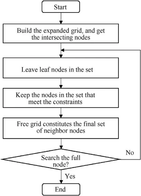
Fig.7.Flow chart of neighbor node search.
3.Improved lazy theta* algorithm
Before introducing the improved algorithm,some variables and functions of the algorithm are defined.
Definition 1.Record the current node ass,the neighboring node of the current node iss′,the starting node issstart,the ending node issgoal,and the Euclidean distance is expressed byeuc(s,s′).
Definition 2.The node coordinate is the grid center coordinate.For the given starting node and ending node coordinate,the algorithm takes the starting grid node coordinate as the starting node coordinate,and the ending grid node coordinate as the ending node coordinate.
Definition 3.Define the Euclidean distance cost betweensands′asc(s,s′).The Manhattan distance cost betweensandsgoalis defined ash(s).
Definition 4.The line-of-sight algorithm for judging whether there is an obstacle between two nodes is represented bylineofsight(s,s′).TheNeighb(s)is the set of neighbor nodes ofs.The argmin(s)can get the node with the lowest cost in the intersection set of theNeighb(s)and the close list.
The algorithm first expands obstacle grids on the original map information,then builds the octree map,and then uses the improved lazy theta* algorithm to search path.Improved lazy theta* algorithm modifies the neighbor node search,line-of-sight algorithm and heuristic weight adjustment,etc.Through these improvements,the desired path is finally found.
3.1. Line-of-sight algorithm
Line-of-sight algorithm can judge whether there are obstacles between two points.For grid matrix environments,the line-ofsight algorithm and the line drawing algorithm are very similar.The line drawing algorithm needs to calculate the position of the grid that is filled when the line is drawn on the grid matrix.For lineof-sight algorithm,a line is drawn between two points to determine whether there are obstacles on the line.
Let the coordinates of the two grids be(x0,y0,z0)and(x1,y1,z1),dx,dy,dzare the difference of the three-axis coordinates of the two points,idis a variable that controls whether the line-of-sight algorithm ends,anddis the maximum of the |dx|,|dy|,|dz|.Thestepis the step size,anddistis the distance between the two points on the two-dimensional plane,and the calculation equation is as follows:
The flow chart of line-of-sight algorithm is shown in Fig.8.In this figure,(ix,iy,iz)is the coordinate of the current step,andmap[x][y][z]==1 indicates that there is obstacle in the grid at coordinate(x,y,z).
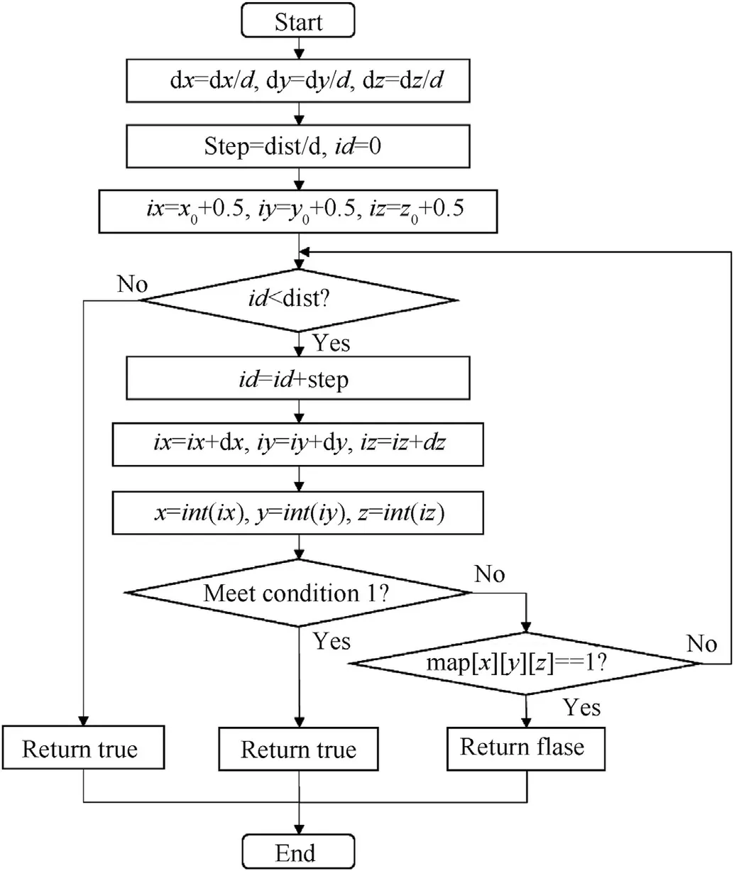
Fig.8.Line-of-sight algorithm.
In Fig.8,condition 1 is shown in Eq.(6),andlen1 is the maximum size of the map.
When the return value is true,there is no obstacle on the line between two points.When the return value is false,there are obstacles on the line between two points.
3.2. Heuristics weight adjustment
In the process of neighbor node search,the form of cost function can be expressed as
whereg(s)represents the true cost from the starting node to the current nodes,h(s)represents the estimated cost of the current nodesto the ending node,and ε is the heuristic weighting factor(ε ≥1).The update of the heuristic weight is related to the location of the current nodes.If the distance between the current node and the ending node is farther,the planning speed will be faster.If the current node is closer to the ending node,the planning accuracy is higher.The update method is as follows:
where △ε can be adjusted according to requirements.By increasing the weight factor of the heuristic,the search direction of the algorithm tends to end the node,thus reducing the search time of the algorithm.However,the weight of the heuristics should not be large,otherwise the algorithm will no longer have acceptability and will not satisfy the consistency condition.
3.3. Path planning based on improved lazy theta* algorithm
The main program of the improved lazy theta* algorithm is based on the lazy theta*algorithm,and the octree map modeling is added.The cost calculation method in the algorithm is described in detail in section 3.2.The main steps of the algorithm are as follows:
(1) Processing the planning map,expanding the obstacles,and building an octree map model based on the data structure of octree;
(2) Constructing open list and close list.During the search,the nodes waiting to be searched are added to the open list,and the searched nodes are added to the closed list;
(3) Inserting the start node into the open list;
(4) If the open list is empty,the calculation is stopped and the path search fails,otherwise performs the next step.
(5) Selecting the node with the minimum cost in the open list as the new current nodes,removingsfrom the open list and inserting it to the close list;
(6) Determining whethersis visible to its parent node.If the two points are visible,the algorithm performs the next step.Otherwise,the algorithm needs to find the node with the minimum cost from the intersection of theNeighb(s)and the close list,and set it as the parent node ofs;
(7) Determining whether the current node is the end node?If it is the end node then the path is found.Otherwise search for neighbor nodes and add them to the open list,and return to Step 4).
If the path is found,the complete path is obtained according to the relationship between the nodes.The main program flow chart of the improved lazy theta*algorithm is shown as follows (Fig.9).
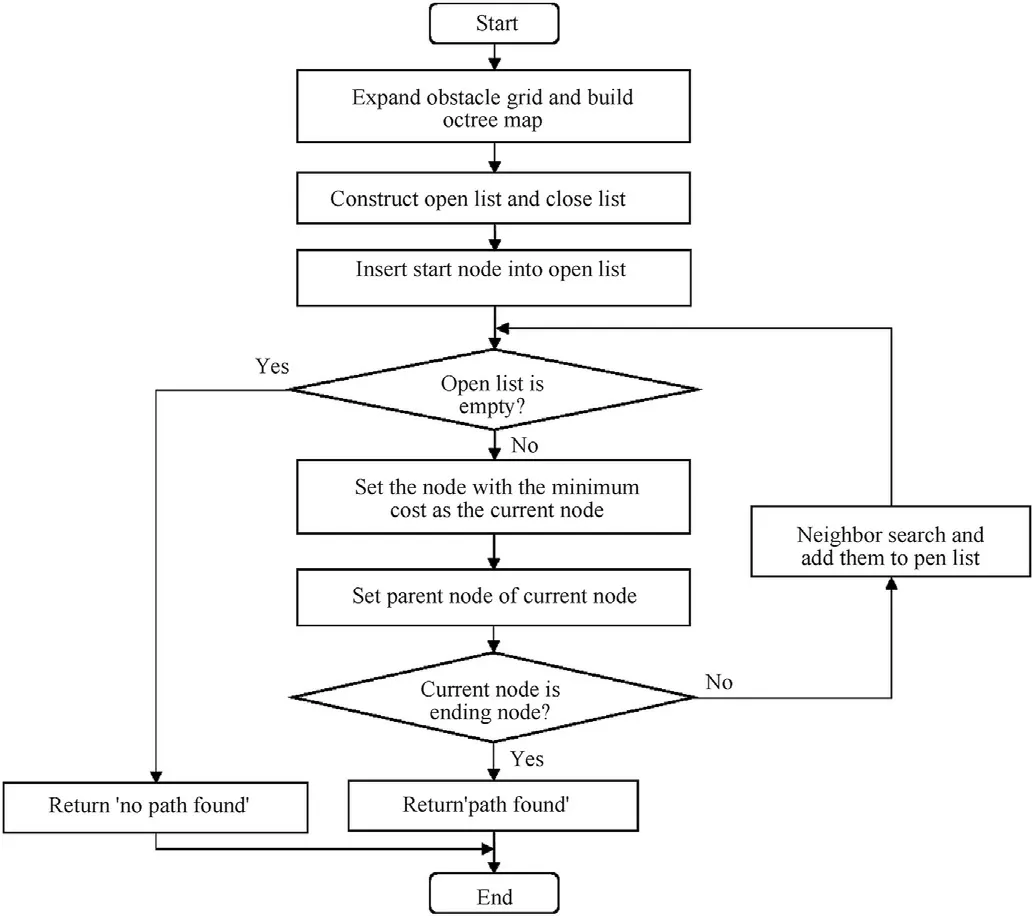
Fig.9.Flow chart of algorithm.
In order to explain the algorithm clearly,the pseudocode of the main part of the algorithm is given below.The algorithm main function is shown in the pseudocode in Fig.10.FunctionMapCreate(map)is the octree map building function.FunctionSetvertex(s)sets parent node of current node.UpdateVertex(s,s′)updates the cost of adjacent nodes′.
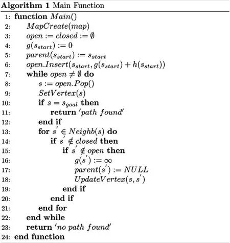
Fig.10.Main function.
The sub-function is divided into two parts,one of which is shown in the pseudocode in Fig.11.This part is the basic subfunction of lazy teta * algorithm.FunctionSetvertex(s)determines whether s and its parent node are visible,corresponding to line 9 in the main function.UpdateVertex(s,s′)updates the cost of adjacent nodes′,corresponding to line 18 in the main function.ComputeCost(s,s′)is the function thatUpdateVertex(s,s′)needs,which calculates the cost of nodes′and sets its parent node.
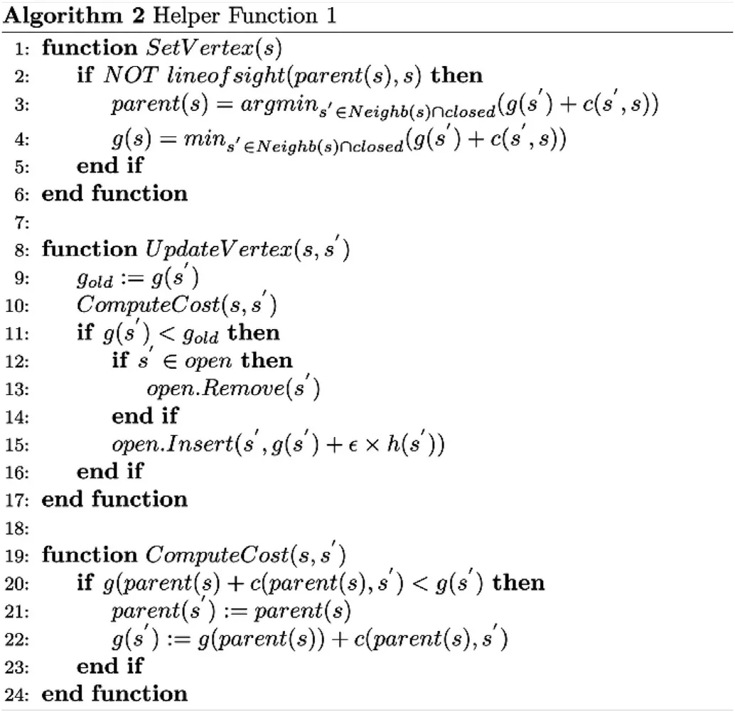
Fig.11.Help function 1.
Another part of the sub-function is shown inHelperFunction2 in Fig.12.This part is octree map modeling and neighbor node search functions.MapCreate(map)is a function which builds an octree map based on the map information after the obstacle grids are expanded,corresponding to line 2 in the main function.The function is a recursive function that constantly calls itself until the map is divided into the smallest grid of constraints and finally returns the root noderoot.Node()is a node,set as a class in the program,which stores some information,including coordinate,size,node state,and so on.Theroot.valuemarks whether the node is obstacle grid,Trueindicates free grid,andFalseindicates obstacle grid.AllValueSame(map)is used to determine whether the grid in the map cube is in the same state.If the states are the same,the blocking of map is no longer continued,and the node state is marked and set as a leaf node.Theroot.ftopleftis the eighth subgrid of the current grid,and the omitting part is the construction of the other seven sub-grids,and the method is the same asroot.ftopleft.
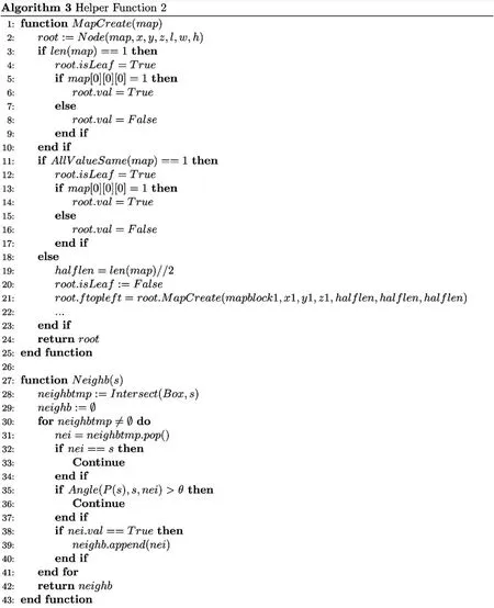
Fig.12.Help function 2.
Neighb(s)is a neighbor node search function,and the function finally returns a set of neighbor node that meets the constraints,corresponding to line 13 in the main function.The function first usesIntersect(Box,s)to get the leaf nodes adjacent tos,then calculates the angle in the path according toAngle(P(s),s,nei),takes the nodes within the maximum yaw angle θmaxand the maximum pitch angle φmax,and finally adds the free grid to the set of neighbor nodes.
4.Simulation results and analysis
To verify the effectiveness of the improved Lazy Theta* algorithm,Windows 10 is used as the platform,and Python 3.6 is used to simulate the programming environment.The simulation hardware platform is Intel Core i5 4210 M processor,which has a clock speed of 2.6 GHz and 8 GB of memory.Under the same hardware platform,the algorithm is verified by using different sizes of maps.Then,in order to further illustrate the role of the algorithm,the ACO algorithm,improved ACO algorithm in Ref.[13],Improved RRT algorithm in Ref.[15],the sparse A* algorithm and the lazy theta*algorithm are selected as the comparison objects.In the case of a fixed starting position,a fixed ending position,and the same map,comparative experiments are conducted to analyze the algorithm.Finally,the planned path is transmitted to the UAV for actual flight verification.
4.1. Simulation results
In the simulation study,the parameters are selected as follows:the maximum yaw angle is 60°,the maximum pitch angle is 45°;the minimum relative height is 0.1 km;the minimum path length is 0.1 km;the initial heuristic weight coefficient is 1.3;the minimum grid length,width and height both are 0.1 km.
First,on the mountain map 1 with the size of 64×64×64,the algorithm is used to search the path.In map 1,the first peak of mountain threat is (2 km,1.8 km,1.1 km),the second peak is(4.2 km,2 km,1.5 km),and the third peak is(3.5 km,4 km,2 km).Set the starting position of the UAV to(0.4 km,0.4 km,0.4 km),the ending position is(6 km,6 km,1.2 km).The path planned without the line-of-sight algorithm is shown in Fig.13,and the planned path with the line-of-sight algorithm is shown in Fig.14,where the black box is the sparse grid where the path node is located.The black line segment represents the path of UAV.
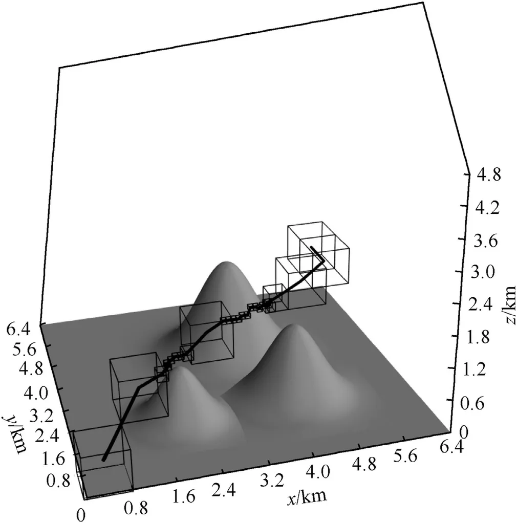
Fig.13.Path without the line-of-sight algorithm in map 1.
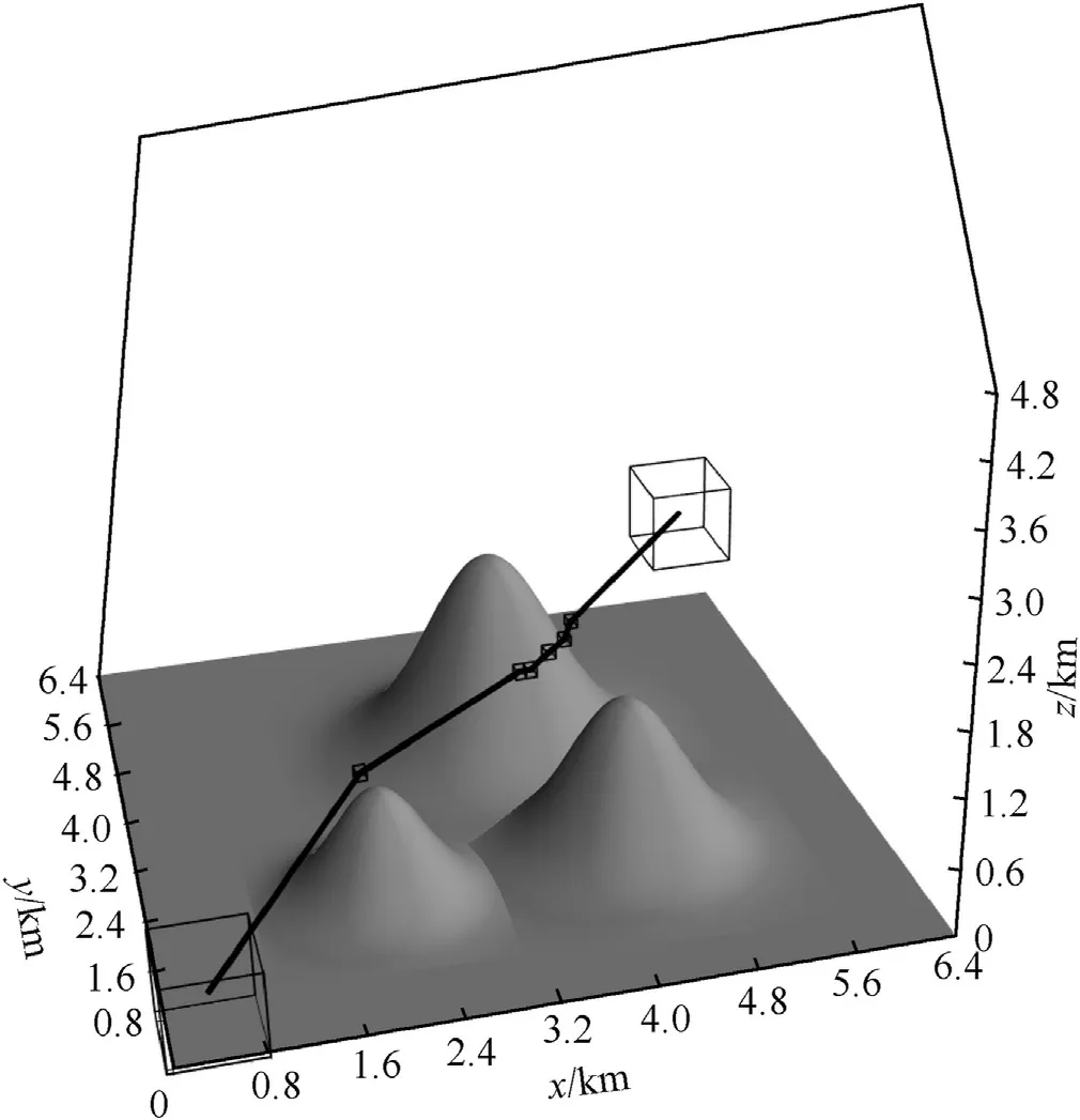
Fig.14.Path in map 1.
Add threat area to map 1 to form map 2.The first center of the sphere threat area is (1.2 km,0.9 km,0.4 km),and the radius is 0.4 km;the second center of the sphere threat area is(1 km,3 km,0.5 km),and the radius is 0.5 km.The cylinder threat area is weather threat,the plane center coordinates are (4.7 km,5.3 km),the radius is 0.5 km,and the height is 1.5 km.The start and end position of the search are the same as before.The path planned without the line-of-sight algorithm is shown in Fig.15,and the planned path with the line-of-sight algorithm is shown in Fig.16.
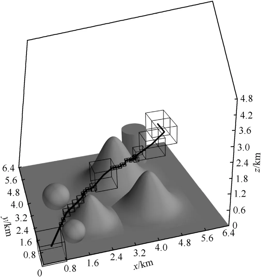
Fig.15.Path without the line-of-sight algorithm in map 2.
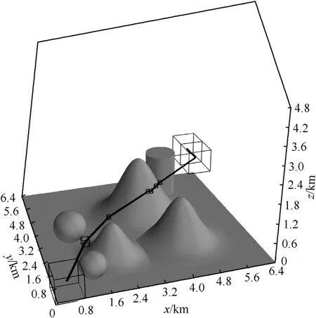
Fig.16.Path in map 2.
On the threat map 3 with the size of 64×64×64,the algorithm is used to search the path.In the map 3,the cylinder,sphere and cube are the threat area.Set the starting position of the UAV to(0.4 km,0.4 km,0.4 km),the ending position is(6 km,6 km,1.2 km),The planned path is shown in Fig.17.
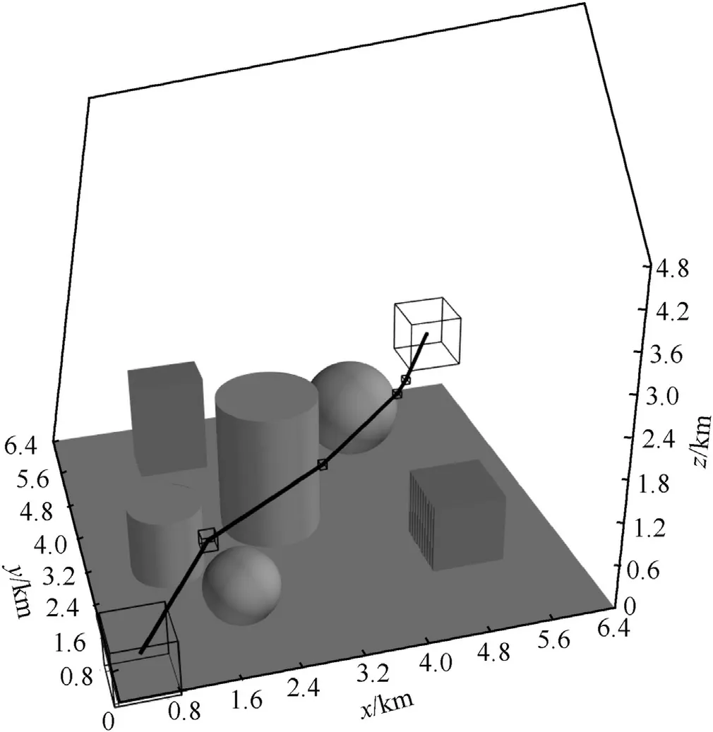
Fig.17.Path in map 3.
On the mountain map 4 with the size of 128 × 128 × 128,the algorithm is used to search the path.In map 4,the first peak of mountain threat is (4 km,3.6 km,2.2 km),the second peak is(8.4 km,4 km,3 km),and the third peak is(7 km,8 km,4 km).Set the starting position to (0.8 km,0.8 km,0.8 km),the ending position is (12 km,12 km,2.4 km),and the planned path is shown in Fig.18.
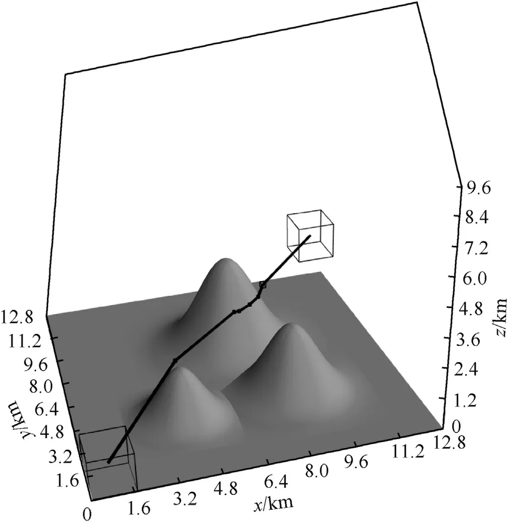
Fig.18.Path in map 4.
In different maps,the information of the path planned by the improved lazy theta*algorithm is shown in Table 1.
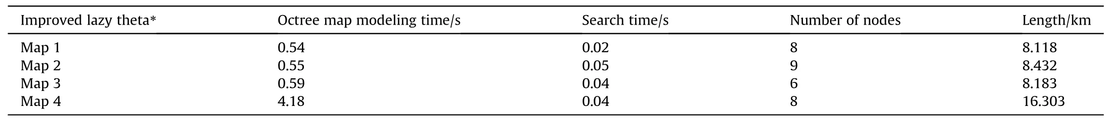
Table 1 Path data of different map.
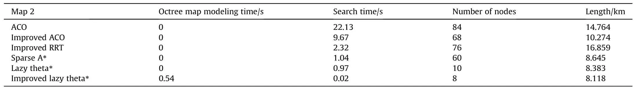
Table 2 Path data of different algorithm in map 1.
From the visual results of different maps,the improved lazy theta* algorithm can effectively solve the problem of threedimensional path planning for UAV.The planned path can keep a safe distance from the obstacles because the obstacles are expanded.Due to the angle constraint in the algorithm,the yaw angle and pitch angle of UAV at the path node are less than the preset extreme value.Because the line-of-sight algorithm can delete redundant nodes,the number of nodes in the path is low.
Analysis of the data in Table 1 shows that the following conclusions.When the terrain is complex,the octree map modeling time and path searching time will increase.When the grid map in three-dimensional space increases,the map modeling time increases and the path search time becomes longer,but the number of path nodes does not change much.Moreover,the octree map modeling in the algorithm requires a certain time.In practical applications,the octree map data can be directly imported into the algorithm,which saves the time of mapping modeling.
4.2. Comparative simulation
On the mountain map 1 with the size of 64 × 64 × 64,set the starting position of the UAV to(0.4 km,0.4 km,0.4 km),the ending position is(6 km,6 km,1.2 km).The ACO algorithm,improved ACO algorithm in Ref.[13],Improved RRT algorithm in Ref.[15],sparse A* algorithm,lazy theta* algorithm and improved lazy theta*algorithm are used to search the path,and the search time,the number of nodes and the length are recorded.
On the mountain map 2 with the size of 64 × 64 × 64,set the starting position of the UAV to(0.4 km,0.4 km,0.4 km),the ending position is (6 km,6 km,1.2 km).The information of the path planned by different algorithm is shown in Table 3.
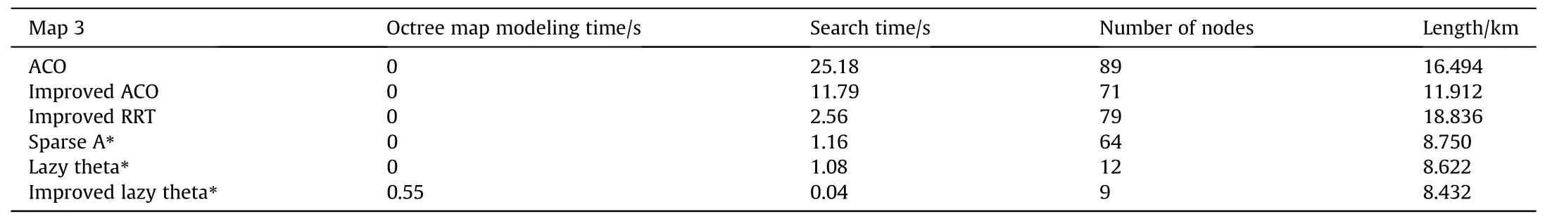
Table 3 Path data of different algorithm in map 2.
From the analysis of the data in Table 2 and Table 3,it is clear that ACO algorithm,improved ACO algorithm and improved RRT algorithm have poor performance,with long algorithm search time,high number of nodes and long length.This is due to the excessive number of path nodes searched by the algorithm.Sparse A* Algorithm has a short search time and a low cost,because it is highly suggestive and has few search nodes.The lazy theta*algorithm has a long search time,a small number of nodes,and a slightly shorter length.The lazy theta* algorithm is judged by the line-of-sight algorithm,and the intermediate node can be omitted,hence the number of nodes is small.By reducing the number of nodes,the algorithm also reduces the path searching time and path cost.The improved lazy theta*algorithm has short search time,short length and few nodes.The algorithm in this paper keeps the advantages of lazy theta* algorithm and further reduces the path cost by constructing octree map,which makes the path search time significantly reduced.
4.3. Actual flight verification
In order to verify the actual flight feasibility of the planned path,the DJI Matrice M600 Pro UAV is used as the platform.At the same time,the manifold 2 airborne computer is installed on the M600 Pro to make it have the function of automatic cruise.On the mountain map 2 with the size of 64 × 64 × 64,set the starting position of the UAV to(0.4 km,0.4 km,0.4 km),the ending position is(6 km,6 km,1.2 km).The planned path is shown in Fig.16.Since the M600 Pro UAV can only fly short distances,the length,width and height of the minimum grid will be set to 1 m when the UAV flies.The length,width and height of the minimum grid will be set to 100 m when drawing.The UAV and remote control equipment are shown in Fig.19.The flight diagram of UAV is shown in Fig.20.
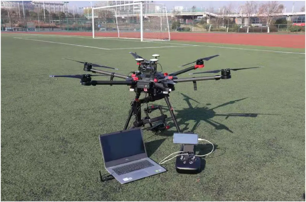
Fig.19.UAV and remote control equipment.
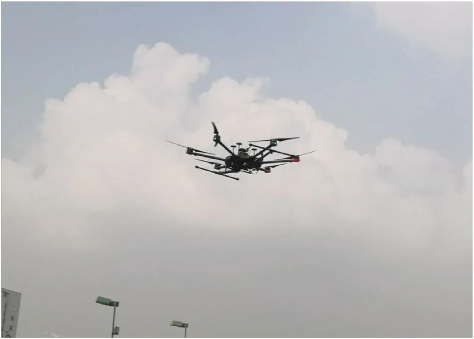
Fig.20.The flight diagram of UAV.
The Manifold 2 airborne computer receives the planned flight path and then performs actual flight verification.The path planned by the algorithm consists of a series of path nodes,which record the three dimensional coordinates of the position.For the whole path,a series of coordinate deviation are obtained by subtracting the coordinates of the previous node from the coordinates of the latter node.The coordinate deviation is continuously sent to the manifold 2 airborne computer as a flight command,and the UAV can fly along the planned path.The actual flight path is shown in Fig.21.
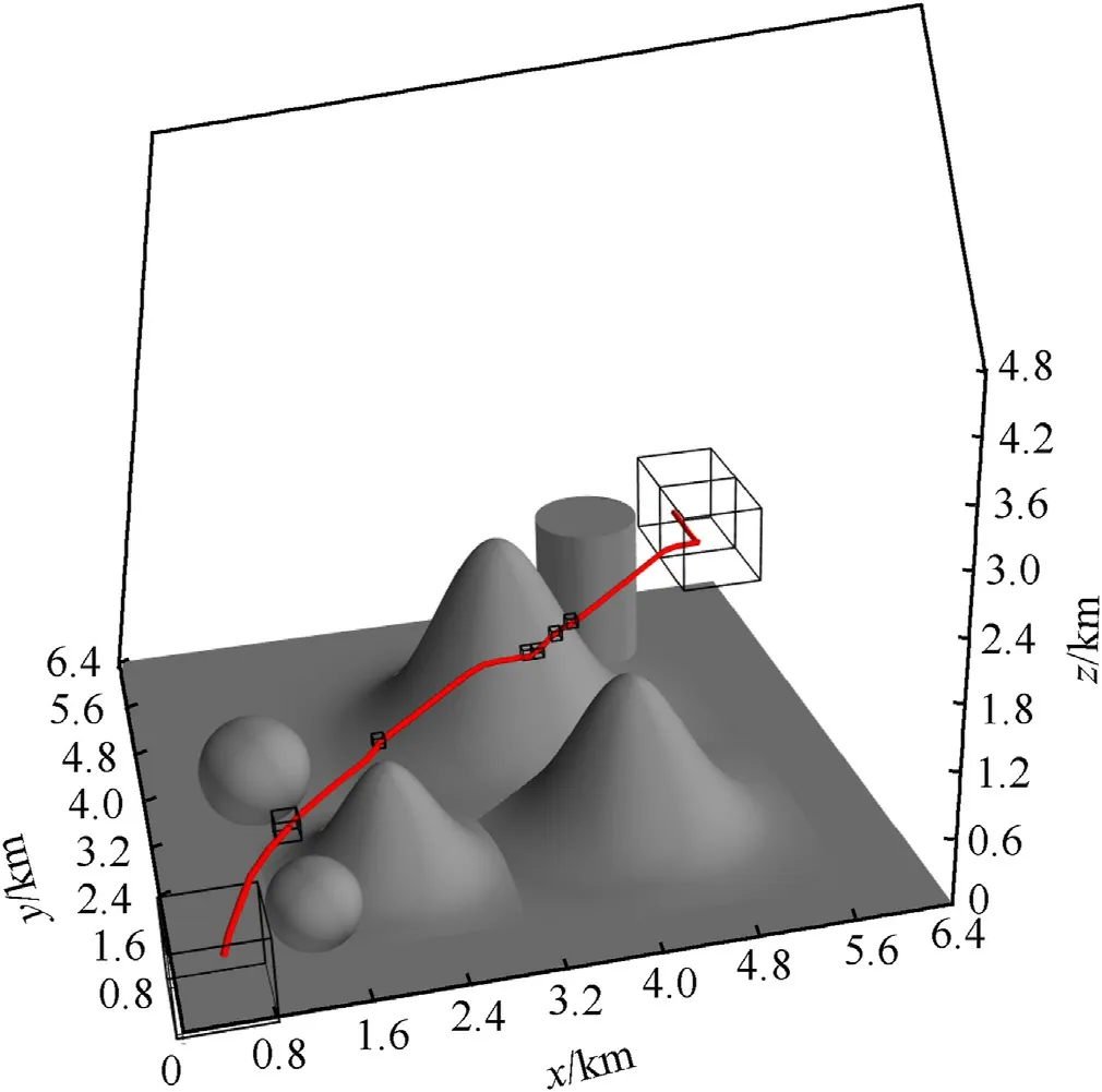
Fig.21.Path in map 2.
The actual flight distance and position deviation of the UAV are shown in Table 4.

Table 4 Path data of actual flight.
According to the visualization results and flight data,the deviation between the actual flight path and the planned flight path is small.The UAV can track the planned path well,which verifies the effectiveness of the algorithm.
5.Conclusions
(1) In this paper,an improved algorithm based on lazy theta*algorithm is proposed.The obstacle grid expansion is used to keep the UAV and the obstacle at a safe distance,and the octree data structure is used to build a map with fewer path nodes.lazy theta*is used to improve the speed of the search and the smoothness of the path.The neighbor node search,line-of-sight algorithm and heuristic weight adjustment are improved.Thus,the improved algorithm is successfully applied to the octree map,and the paths are finally planned.
(2) Compared with the path planned by ACO algorithm,improved ACO algorithm in Ref.[13],Improved RRT algorithm in Ref.[15],the improved lazy theta*algorithm tends to search in the target direction when it searches nodes in the octree map.Therefore,the search speed is fast and there are fewer search nodes.At the same time,the node path cost is calculated when searching,and the path with less path cost can be obtained.Finally,the redundant nodes are deleted by the line-of-sight algorithm,which can make the path smooth and less expensive.Therefore,the improved lazy theta* algorithm can plan fast,smooth,safe and low cost paths.
(3) The algorithm is a fast path planning method in threedimensional static environment.The position error of the algorithm in the UAV flight verification meets the requirements,so it can be applied to the military UAV mission planning system,which is conducive to the military UAV to perform various complex tasks and improve the combat capability.At the same time,the military UAV is facing sudden threats when performing tasks.It is necessary to quickly reconstruct the map and plan a new path.Octree map has the characteristics of real-time construction.And the algorithm has fast search speed and excellent search results.Therefore,the next step will study the online path planning method of military UAV in dynamic environment,includes establishing more effective map and threat model,optimizing the calculation function and actual flight verification.
Declaration of competing interest
The authors declare that they have no known competing financial interests or personal relationships that could have appeared to influence the work reported in this paper.
Acknowledgements
This work was supported in part by the National Natural Science Foundation of China under Grant U2013201 and in part by the Key R&D projects (Social Development) in Jiangsu Province of China under Grant BE2020704.
杂志排行

Defence Technology的其它文章
- Numerical and experimental evaluation for density-related thermal insulation capability of entangled porous metallic wire material
- A new Ignition-Growth reaction rate model for shock initiation
- Effect of interface behaviour on damage and instability of PBX under combined tension-shear loading
- Sensitivity analysis and probability modelling of the structural response of a single-layer reticulated dome subjected to an external blast loading
- Deep hybrid: Multi-graph neural network collaboration for hyperspectral image classification
- Experimental study of polyurea-coated fiber-reinforced cement boards under gas explosions