Variation of Small Scale Magnetic Fields Over a Century using Ca-K Images as Proxy
2023-05-29JagdevSinghMuthuPriyalRavindraLucaBertelloandAlexeiPevtsov
Jagdev Singh, Muthu Priyal, B.Ravindra, Luca Bertello, and Alexei Pevtsov
1 Indian Institute of Astrophysics, II Block, Koramangala, Bengaluru–560 034, India; jsingh@iiap.res.in, ravindra@iiap.res.in
2 National Solar Observatory, 3365 Discovery Drive, Third Floor, Boulder, CO 80303, USA
Abstract A combined uniform and long-time series of Ca-K images from the Kodaikanal Observatory, Mount Wilson Observatory and Mauna Loa Solar Observatory was used to identify and study the Ca-K small-scale features and their solar cycle variations over a century.The small scale features are classified into three distinct categories:enhanced network,active network and quiet network.All these features show that their areas vary according to the 11 yr solar cycle.The relative amplitude of the Ca-K network variations agrees with that of the sunspot cycle.The total area of these small-scale features varies from about 5%during the minimum phase of the solar cycle to about 20% during its maximum phase.
Key words: Sun: activity – Sun: chromosphere – (Sun:) sunspots
1.Introduction
The variable magnetic field of the Sun causes processes that influence the heliosphere and the Earth’s upper atmosphere(Bertello et al.2020).The main cause for this variability is the complex dynamo process,believed to be running at the bottom boundary layer of the solar convection zone, known as the tachocline (Gilman 2000; Weiss & Tobias 2000).The operation of the dynamo process leads to the formation of sunspots and other related activity on the solar surface(Choudhuri et al.1995; Hazra et al.2014; Karak et al.2014;Hazra&Nandy 2016;Charbonneau 2020).The occurrence and characteristics of the sunspot cycle have been studied by several researchers (Howard et al.1984; Howard 1992, 1993;Howard et al.1999,2000;Sivaraman et al.2003;Mandal et al.2017; Ravindra et al.2022) using long data series spread over several decades.
Total solar irradiance (TSI) has been measured only since 1978, by various radiometers from space (Hickey et al.1980;Willson&Hudson 1998).Reconstructions of past variability of TSI are mostly based on sunspot data.But, sunspot records provide limited information on the facular and network regions,which are decisive contributors to irradiance variability on timescales of the solar cycle and longer.The reconstructed irradiance from the analyzed Ca-K archives by Chatzistergos et al.(2021) agrees well with direct irradiance measurements and existing reconstructions.Further,they found that the model works for the data taken with different bandpasses and images with different spatial resolutions.The Ca-K archive has some non-uniformity in the contrast of the images on a short and long term basis due to different passbands, changes of films to record the data,sky conditions, development of films,etc.Use of the equal contrast technique(ECT)makes the contrast of the data series the same and thus takes care of these factors.
Apart from the large-scale activity in the form of sunspots and related plage regions visible on the solar surface, the quiet Sun shows a reticular pattern of intense kiloGauss fields known as the magnetic network and small-scale flux concentrations in the areas in between them (Bellot Rubio & Orozco Suárez 2019).A significant fraction of the photospheric magnetic flux resides in the quiet Sun in the form of a magnetic network (Gošić et al.2014).According to Jin et al.(2011), the quiet Sun magnetic field is comparable to the total flux of active regions during the maximum phase of the solar cycle.The emergence and cancellation of the quiet Sun magnetic field couple the different atmospheric layers and may contribute effectively to heating the chromosphere and corona.
Regular observations of the Sun’s magnetic field began in the late 1960s at the Crimean Astrophysical Observatory(Kotov et al.1998), Mount Wilson Observatory (MWO,Livingston et al.1976), Wilcox Solar Observatory (WSO;Scherrer et al.1977) and a few other observatories.As time progressed, techniques and accuracy in measuring the smallscale magnetic field have improved (Plotnikov et al.2021).Schrijver et al.(1998) computed the emergence rate of small bipolar regions and argued that the frequent magnetic reconnections associated with these regions would heat the solar atmosphere.Thus, knowledge of long-term variation in the small-scale magnetic field is vital to understanding the solar atmosphere’s heating.
Magnetic elements appear bright in chromospheric images as indicated in Ca-K&H filtergrams in comparison to photospheric magnetograms (Babcock & Babcock 1955; Leighton 1959;Stepanov & Petrova 1959; Leighton 1964).Sivaraman &Livingston (1982) showed a strong correlation between the Ca-K bright points and small-scale magnetic fields.The plage and networks observed in the Ca-K line can be used as a proxy to study the variations in magnetic fields as there is a strong correlation between Ca-K intensity and magnetic fields(Skumanich et al.1975;Schrijver et al.1989;Ortiz&Rast 2005).Longterm variations in large-scale activity using Ca-K plage areas have been reported in several studies(Foukal 1996;Ermolli et al.2009;Foukal et al.2009;Tlatov et al.2009;Chatzistergos et al.2019;Chowdhury et al.2022).The variations in the Ca-K index(including plages and small-scale network regions)were studied by Bertello et al.(2010).Pevtsov et al.(2016),using the polarity of sunspot magnetic field data and Ca-K intensity,showed that a long-time series of pseudo-magnetograms can be constructed by making use of Ca-K data.
Using 1400 digitized Ca-K spectroheliograms obtained at the Sacramento Peak Observatory between 1980 and 1996,Worden et al.(1998) classified the plage regions, enhanced network (EN), active network (AN) and quiet Sun by defining an intensity threshold value for each of these features.Priyal et al.(2017,2019)attempted to study the variations in the plage and network areas using the digitized Ca-K spectroheliograms obtained at Kodaikanal Observatory (KO) during the period 1905–2007.Averaging of the measured parameters over several months was required because of the large scatter in their values due to different contrasts of the obtained images.The monthly averaged Ca-K parameters were used by several investigators to study the long-term variations (Priyal et al.2019; Devi et al.2021; Temmer 2021).
Bertello et al.(2020) rescaled the intensity of Ca-K MWO images such that the full width at half maximum (FWHM) of the intensity distribution of each image was 0.08.They selected 14,525 images of uniform quality to study the variation in the Ca-K index and chromosphere’s differential rotation.Singh et al.(2021) developed an ECT that makes the intensity distribution of the background chromosphere similar in all images.First, images are subjected to density-to-intensity conversion using step wedge calibration(Priyal et al.2014)and then corrected for the large-scale variations in intensity due to limb darkening and instrumental vignetting.The intensity distribution of the image is normalized to unity.Then, the contrast of all the images was made uniform following the ECT methodology, which involves rescaling the intensities of the image, such that the FWHM of the intensity distribution lies between 0.10 and 0.11 (Singh et al.2021).
Singh et al.(2022) demonstrated that data from different observatories such as KO, MWO and Mauna Loa Solar Observatory (MLSO) could be merged after applying the ECT methodology to reduce time and data gap and make long series with consistent quality data.
Further, Singh et al.(2022) studied the variations in the large-scale magnetic field using Ca-K plages as a proxy.In this paper, we study the variations in small-scale features such as EN,AN and quiet network(QN)areas with time.It is generally believed that EN represents small regions of decaying plages,AN signifies small bipolar regions and QN defines the boundaries of a network.In Section 2, we summarize the data and the associated analysis.Section 3 describes the results of data analysis and in Section 4, we discuss the implications of the results.
2.Data Analysis
Here,we investigate five sets of Ca-K line images from three observatories: KO, MWO and MLSO.The images are Ca-K spectroheliograms obtained at KO from 1905 to 2007 and MWO from 1915 to 1985.There is a gap of 6 months, from 1929 July to December, in the availability of KO data.In addition, there are small gaps of a few days due to cloudy sky conditions.We have not done any interpolation of the parameters derived from the Ca-K images from KO, MWO and MLSO (Precision Solar Photometric Telescope, PSPT)observatory.While comparing the Ca-K parameters of KO and MWO data, we have considered only those days for which images are available from both observatories, as seen in Figure 3 of this paper.For monthly averages also, we have considered the available data only without any interpolation of the parameters.We have also considered Ca-K filtergrams taken at KO from 1997 to 2013 and with PSPT, operated at MLSO from 1998 to 2015.The details of data and analysis may be seen in Singh et al.(2022).
In the following we give the summary of the data analysis.The digitized Ca-K images were centered and aligned such that north of the Sun is up(Priyal et al.2014).This enabled us to fit the Sun’s grid to the image and demarcate latitude zones of 10°each to study the Ca-K line parameters as a function of latitude.Before marking the latitude zones, images were corrected for limb darkening, large scale intensity variations due to instrumental artifacts and sky transparency using the procedure adapted by Priyal et al.(2017,2019).First,we made the polynomial fit to quiet chromosphere pixels in a row and then normalized the intensity values of the original image by its polynomial fit.This was repeated for pixels in each row of the image.The same procedure was applied to the pixels in columns.After this, the resultant image was segmented into eight rings of equal area and each ring in 12 segments of 30°each.After that, 35% of the pixels whose intensity values are larger in each segment with respect to the remaining 65%values were replaced by the average value of remaining pixels.
The corrected images still have different contrasts on a short and long term basis due to different specifications of the instruments, bandwidth used for taking images, change in emulsion over time,change in chemicals used to develop films,development environment, etc.The density to intensity conversion without proper calibrations is also an issue.The intensity distribution of the Ca-K quiet chromosphere is expected to remain the same with minor variations in the phase of a solar cycle.The occurrence of plages increases only the tail of intensity distribution of the images, with plages being brighter than the quiet chromosphere.Hence, FWHM of the intensity distribution is expected to remain the same with minor variations on a short and long term basis.We have found that FWHM of the intensity distribution for the corrected images for the instrumental observational effects varies by a large amount on a short and long term basis(Singh et al.2021)which needs to be the same.Therefore, we have rescaled the intensity distribution of the images so that FWHM of the intensity distribution becomes the same for all the images using the ECT application.This is done utilizing the relation
Here“I”is the intensity of the contrast corrected image,“Ip”is the intensity of the image and“G”is a varying factor such that FWHM of the intensity distribution of the image attains a value between 0.10 and 0.11.The value of“G”is assumed to be 1.0 to begin with and varied in steps of 0.025.In case of FWHM>0.11 of the intensity distribution, the “G”value is decreased in steps of 0.025 until the FWHM becomes <0.11.Similarly,in case the FWHM <0.10, G is increased until FWHM of the distribution becomes >0.10.Thus, the FWHM of the intensity distribution for all the images lies between 0.10 and 0.11.This interval of 0.10–0.11 for FWHM was chosen because the median value of the FWHM for the data from MWO and KO before the ECT application is ≈0.1.
The FWHM of the intensity distribution of the images varies for the KO spectroheliogram data (1905–2007) on a short and long term scale between 0.02 and 0.32 depending on the contrast of the images (Figures 1 and 2, Singh et al.2022)whereas that of MWO data (1915–1985) between 0.03 and 0.80.More than 50% of images have FWHM of the intensity distribution >0.10.It may be noted that FWHM of the intensity distribution for the filtergrams obtained at KO and MLSO(1997–2015) is <0.08 indicating that filtergrams generally have low contrast as compared to spectroheliograms.This is likely due to larger spectral passband and less spatial resolution of filtergrams as compared to spectroheliograms.The contrast of the images leads to different values of detected features as shown in Table 3 of this paper,even after correcting the images for intensity vignetting due to the instrument.The contrast of the images needs to be the same to study the long term variations in the detected features such as Ca-K plages and networks.This is done by re-scaling the intensities of the image using the ECT procedure that involves making the FWHM of the intensity distribution between 0.10 and 0.11.
Bertello et al.(2020) rescaled the intensity of the images using a different methodology such that the FWHM of the intensity distribution becomes 0.08.Their and our purpose is the same, to achieve uniformity in the data series.With their methodology, Bertello et al.(2020) could generate a uniform time series of only 14 525 images, about 36.5% of the images available at MWO.But, we have rescaled the intensity of images using a different procedure, named ECT such that the FWHM of the intensity distribution lies between 0.10 and 0.11.This way we could analyze all the available images at KO(34,453 images) and 36,050 images from MWO, and generate a uniform time series.The present procedure(ECT)permits the analysis of all the available images whereas that of Bertello et al.(2020) allows the study of part of the available data to make a uniform time series.Hence,gaps in the data series with the ECT procedure are less compared with those with the methodology adopted by Bertello et al.(2020)
The top two panels of Figure 1 display a digitized image and its intensity distribution taken on 2003 December 24,with PSPT at MLSO.The middle two panels feature the corrected image for the instrumental vignetting (using the code developed for KO data) and its intensity distribution.The intensity distribution indicates a relatively narrower FWHM, a signature of low contrast images.The bottom two panels show the image after adjusting the contrast such that the FWHM of the intensity distribution lies between 0.10 and 0.11.
The plages were identified as regions with normalized intensity >1.30 and area >0.2 arcmin2, and EN with intensity>1.30 and area >4 pixels (3 arcsec2).The AN is defined as regions with intensity between 1.2 and 1.3 and QN is between 1.1 and 1.2 with an area >4 pixels (3 arcsec2) (Singh et al.2021).The areas were determined in full-disk images in pixels in the plane of the sky.A lower limit of 4 pixels has been used to avoid the random contribution of single pixels.The regions with intensity <1.1 represent background (quiet) chromospheres.Here, we investigate the variation in small-scale features EN, AN and QN as a function of time and their correlation with sunspot numbers from 1905 to 2015 by combining all the data sets.
Figure 2 depicts the detected plage, and EN, AN and QN areas in white color in the binary format,using the intensity as mentioned earlier and area threshold values from a typical image obtained at PSPT on 2003 December 24.The top-left panel of the figure shows the large-scale plage area, generally seen in the active regions on the Sun.The top-right panel of these figures displays the EN regions in white.The EN regions in the vicinity of plages imply that these are fragments of the decaying plages.The bottom two panels of the figure show the AN and QN areas.AN regions are mostly concentrated in the equatorial (active) regions, whereas QN regions are seen all over the Sun representing the QN.
3.Results
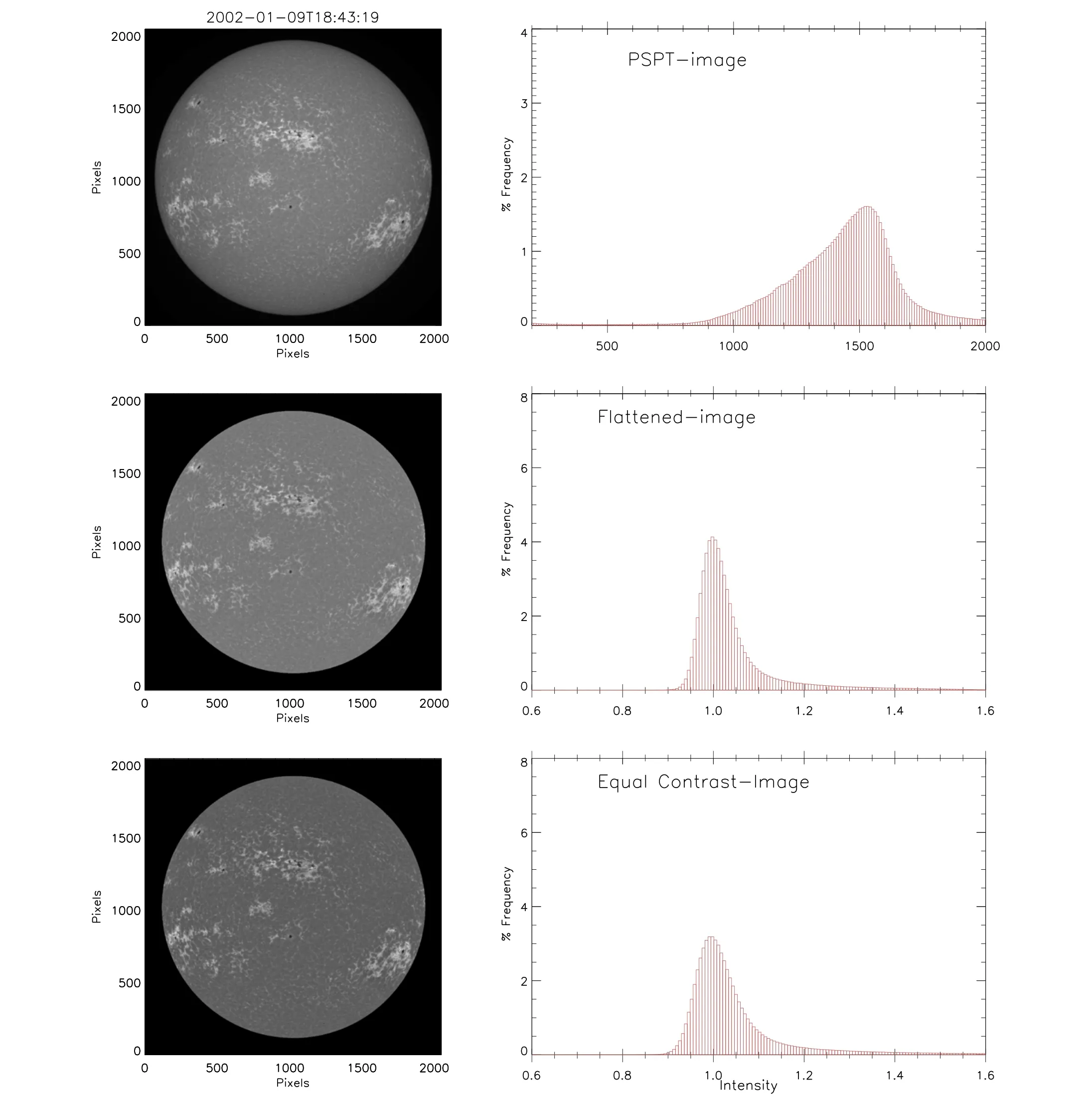
Figure 1.(Top) The Ca-K image taken on 2003 December 24, with PSPT at MLSO and its intensity distribution.(Middle) The flattened image and its intensity distribution using the above mentioned methodology to correct the vignetting due to the instrument.(Bottom)The image and its intensity distribution after applying the ECT application.
First, we compare the measured values of EN, AN and QN areas before and after the ECT application between KO and MWO spectroheliograms to find the effectiveness of ECT in detecting small-scale features and then to study the variations of these parameters with time.Afterward,we combine the ECT corrected data of KO, MWO and PSPT and examine their correlation with the long-standing record of sunspot data.
3.1.Comparison of Network Parameters for KO and MWO Data Before and After the ECT Application
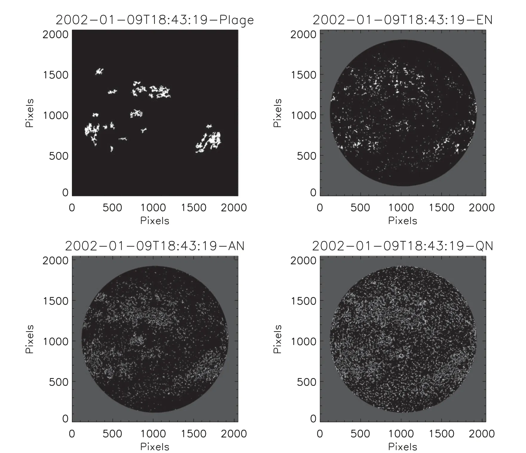
Figure 2.Binary images of the identified plages, EN, AN and QN for the Ca-K image obtained on 2003 December 24, using PSPT at MLSO.
The top two panels in Figure 3 show the scatter plot of EN area in the percentage of solar disk for the KO and MWO data before and after the ECT application on a daily basis.The values of Pearson(linear)correlation coefficients,intercept and slope of the linear fit (red line) are written in each panel.The values of correlation coefficients 0.23 and 0.66 for the EN area before and after the ECT application indicate a significant improvement in the correlation between the two data sets after the ECT.The two panels in the middle row of Figure 3 display the scatter plots of the AN area for the KO and MWO data before and after the ECT application on a daily basis.The values of correlation coefficients (0.27 before ECT and 0.84 after ECT)indicate a large improvement in the correlation after the ECT methodology.In Table 1, we list the Pearson (linear)and Spearman (rank) correlation coefficients (with 99.99%significance level)for all the scatter plots in Figure 3.Similarly,scatter plots of the QN area for KO and MWO in the bottom row of the figure indicate much improvement in the correlation between the two data sets after the ECT application.The values of intercept(nearly zero)and linear regression slopes(0.76,1.0 and 0.97 for EN, AN and QN, respectively) after the ECT application imply that the detected values of these Ca-K parameters agree with each other.The comparison of KO and PSPT filtergram data shows similar results.
3.1.1.Variation of EN, AN and QN Areas with Time for KO and MWO Data
Figure 4(a) shows the percentage of measured EN area for the KO(black dots) and MWO(red dots) data before the ECT application on a daily basis.But after the ECT application, the maximum amplitude of the percentage of EN area decreases from ≈10%(before the ECT)to ≈2%,as seen in panel(b)on a daily basis.Panel(c)of this figure displays the difference (KO—MWO) in the detected values of % EN area on monthly(black dots) and 13 month running average (red dots) before the ECT application.The values show that the differences of%EN area vary between-4%and+4%,even after averaging the data over a long period.Panel (d) demonstrates that the difference in(KO–MWO)%EN area after the ECT application on a monthly average basis varies between-0.5%and+0.5%.It is a small difference considering the nature of data obtained with two instruments with different specifications and weather conditions.The mean value of the difference is 0.19% with a standard deviation(SD)value of 0.10%.This suggests that the two data sets can be combined to decrease the gaps in the longtime series of Ca-K images.

Figure 3.(Top) The EN area in percentage of solar disk detected from KO spectroheliograms vs.that from MWO data before and after the ECT application,respectively,for the period 1915–1985 on a daily basis.(Middle)The scatter plots for the%AN area before and after the ECT application on a daily basis.(Bottom)The same for% QN area.It may be noted that plots after the ECT application are on a magnified scale (about a factor of 1.8) as compared to before the ECT.

Table 1 The Pearson (Linear) and Spearman (Rank) Correlation Coefficients for the Scatter Plots between KO and MWO Data before and after ECT for EN, AN and QN Areas
Figure 5(a)affirms that detected values of%AN area for KO and MWO data plotted on a daily basis have significant differences before the ECT application.Panel(b)indicates that after applying the ECT,the detected values of the percentage of AN area for KO and MWO images agree with each other,even on a daily basis.The plot in panel(c)shows that the difference of(KO—MWO)of AN area on a monthly average is ≈4%and increases after 1960.After the ECT application, the mean difference in KO and MWO values is <1%, as seen in panel(d).Similarly, Figure 6 for the QN area shows a significant improvement in the agreement between the two data sets after the ECT application on a daily and monthly basis.The plot of the percentage of QN area as a function of time in panel (a)does not show significant solar cycle variations before the ECT application, but these become apparent after the ECT application, as seen in panel (b).
3.2.Correlation Between Ca-K Network Parameters and Sunspot Numbers
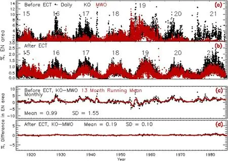
Figure 4.(a) The percentage of EN area as a function of time for the period 1915–1985, common period of observations at KO (black dots) and MWO (red dots)before the ECT application on a daily basis.(b) The percentage of EN area after the ECT application to the images on a daily basis.The solar cycle numbers are indicated in the panels.(c),(d)A difference(KO—MWO)in percentage of EN area(black dots)on a monthly average and 13-month running average(red dots)basis before and after the ECT application, respectively.The mean and SD values are written in the bottom two panels.
We compare the measured percentage of small-scale active(EN+AN+QN, hereafter called “active area”) area after the ECT application with the sunspot number to determine the relationship between the two.The upper-row left and right panels of Figure 7 feature a scatter plot of the daily active area expressed in percentage versus sunspot number(WDC-SILSO,Royal Observatory of Belgium,Brussels,https://wwwbis.sidc.be/silso/) for the KO and MWO spectroheliograms, respectively.In the plot, the red line shows the linear regression.We see that the fraction of solar disk covered by active area pixels(EN+AN+QN) varies between about 4% and 15%, of which the QN is the most significant contributor (Figure 6).
We have tried higher degree polynomial fits to these data sets but found that a linear fit is best among these.It appears that the relationship between these two parameters is linear up to sunspot number <250, but after sunspot number >250, the percentage of the area of small-scale features remains the same or increases by a small percentage.The values of Pearson(linear) correlation coefficient 0.64 (KO) and 0.76 (MWO)indicate a confidence level of >95%.In Table 2, we list the Pearson(linear)and Spearman(rank)for all the scatter plots in Figure 7.Nearly the same values of slope and intercept for the KO and MWO data imply that the detected combined%area of small-scale features agrees with each other very well.We have performed a similar analysis using sunspot areas and found comparable results.
The bottom two panels of the figure indicate that the detected percentage of the area of small-scale features from the PSPT images is more than that from KO filtergrams by about 30%.The reason for this may be the passband of the Ca-K filter,the spatial resolution of images and the photometric accuracy of the detector.
3.3.Solar Cycle Variations of Ca-K Network Area
We have shown that the percentage area of solar disk occupied by small-scale features detected from the KO and MWO spectroheliograms agrees with each other after the ECT application.To study the correlation of small-scale features over 1905–2015 with reliable activity indexes such as sunspots,we have combined the respective detected parameters of Ca-K small-scale features from spectroheliograms and filtergrams obtained at KO, MWO and MLSO (PSPT) on a daily basis.Then we computed monthly averaged data for the Ca-K features and sunspot numbers.There are periods when much less data are obtained during a month due to rainy periods,which may cause some scatter in the data.To smoothen these types of variations for comparison between Ca-K features and sunspots on a long term basis, we have further taken a 3-monthly running mean of the data.Figure 8(a) shows the percentage of EN area monthly (black dots), and the red curve indicates the monthly mean of sunspot number for comparison.The variations in the relative amplitude of both these parameters for solar cycles 14–24 agree with a minor difference.
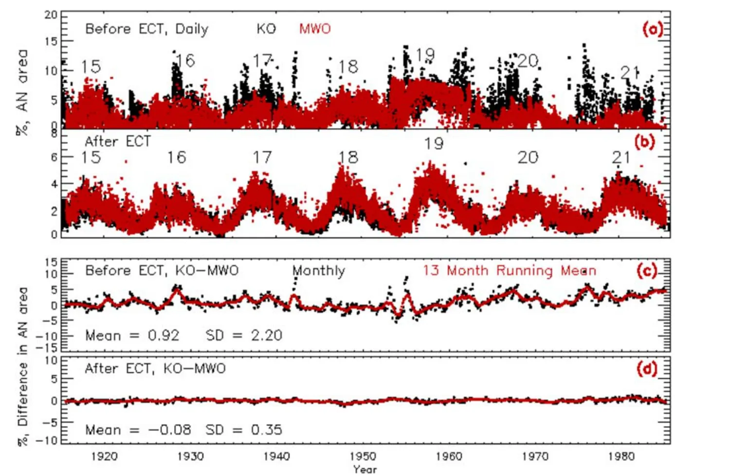
Figure 5.Same as that of Figure 4 but for AN area.
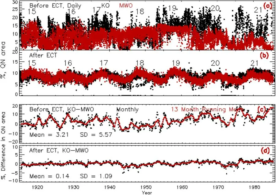
Figure 6.Same as that of Figure 4 but for QN area.
The difference during cycle 21 is due to the quality of the KO data(Singh&Aleem 1988;Priyal et al.2019).The%EN area becomes nearly zero during the minimum phase of the solar cycle, and amplitude during the maximum phase varies between 0.6% and 1.1% of the area of the visible disk when considered on a 3-monthly average basis.The plot of % AN area and sunspot number(panel(b))indicates that even during the minimum phase of the solar cycle, the AN area occupies about 0.5%area of the visible disk,and the amplitude of the%AN area at maximum phase varies between 2%(solar cycle 14)and 4%(solar cycle 19,the strongest cycle of the 20th century).The variation in the relative amplitude of the percentage of AN area agrees well with those of sunspot numbers for all the cycles studied.Panel (c) indicates that % QN area varies between 4%and 7%during the minimum of the solar cycle and 9%–11% during the maximum phase during the 20th century.The plot indicates the area occupied by small-scale features is 5%–8% during the minimum and 10%–16% during the maximum phase of solar cycles when averaged over three months.
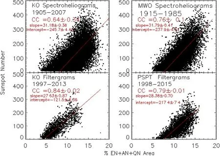
Figure 7.(Top left) The plot of percentage of small scale features (EN+AN+QN) area, hereafter called “active area”, detected from KO spectroheliograms vs.sunspot number on a daily basis along with the linear fit(red line)to the data.(Top right)A scatter plot between the percentage of EN area and sunspot number for the MWO spectroheliogram.(Bottom) The scatter plots for KO and PSPT (MLSO) filtergrams.The values of correlation coefficient, slope and intercept of the linear regression are shown in the respective panels.
3.4.Discussions and Conclusion
With the application of ECT to the KO and MWO Ca-K images, the detection of small-scale features has become accurate (panel (b) of Figures 4–6).Most of the images were obtained in the Ca-K line center.But,some changes were made in the instruments over the long period of observations spanning over a century at KO and MWO.Therefore, a significant portion of the data has (1) high contrast images(larger FWHM of the intensity distribution of the image)due to the small passband of the instrument and/or setting of exit-slit of spectroheliograph at the blue-wing of the Ca-K line and/or use of high contrast emulsion, etc; (2) low contrast images(smaller FWHM of the intensity distribution of the image)because of large passband and/or setting of the exit slit away from Ca-K and/or use of low contrast emulsion and/or weather conditions (cloudy sky), etc.The ECT procedure has been applied to make all the images of uniform nature (Singh et al.2021) by rescaling the intensity of images such that the FWHM of the intensity distribution lies between 0.10 and 0.11.Earlier reports about the QN area have not made any distinction between EN,AN and QN as we have done.Hence the total area of small-scale features (EN+AN+QN, hereafter called QN)needs to be compared with the earlier reported QN area.During the 19th solar cycle, MWO data were obtained with a narrow passband (Tlatov et al.2009) yielding large FWHM of the intensity distribution and high contrast.Table 3 gives the FWHM of the intensity distribution before the application of the ECT for KO and MWO sample images during this period and values of the QN derived from these images before and after the ECT application.The top 12 rows indicate that FWHM and QN values for KO are much less as compared to those for MWO data.
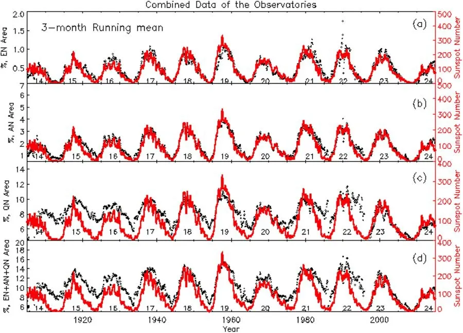
Figure 8.(a) The percentage of EN area (black dots) as a function of time for the period 1905–2015 on a monthly basis with running average over 3 months for merged data of KO,MWO and MLSO after the ECT application.The red curve signifies the sunspot number for comparison.(b),(c)The same for the percentage of AN and the percentage of QN area respectively.(d) The total percentage of small scale features (EN + AN + QN) and the sunspot number in black and red,respectively.The solar cycle numbers are indicated in the panels.
The QN area values for high contrast images obtained at MWO and low contrast images at KO on the same day before the ECT application indicate a significant difference between the two (~20%).The difference in QN areas appears to be correlated with the difference in FWHM values.The large difference is due to observational differences and needs to be corrected.This large difference in values before the ECT application is due to some of the differences while making observations,such as centering the Ca-K line on the 2nd slit of the spectroheliograph,width of the passband of KO and MWO data, photographic emulsion used, chemical used to develop the photographic plates, environment while developing the plate, density to intensity conversion in the absence of calibration on earlier plates, etc.The ECT application corrects the images for these effects and makes the data have a similar nature.After this the difference in values decreases to only<2%.The bottom three rows in Table 3 show minor differences between FWHM of intensity distributions and QN areas for KO and MWO data before and after the ECT application to the images.After the ECT application, the derived QN area values may be considered the representative value for the Ca-K images obtained at the line center.The decrease or increase in the QN area may be regarded as the correction for the high and low contrast images, respectively.
Foukal & Milano (2001) used only 27 images, and 3 Ca-K images with the highest quality(not defined)for each minimum phase during 1914–1996.They found that the quiet Sun network occupied between 10%and 19%(see Figure 3 in their article) during the minimum phase of the solar cycle.The significant variations in their detected QN might be due to different contrasts of the selected images.The images they selected might be of high contrast data yielding high values for QN areas, as we have found.Further, their data are very limited, especially during the minimum period.Present uncorrected data (Figure 3, left in the current manuscript)show that the QN varies between 5% and 40% of the disk(aggregate of EN, AN and QN) for MWO and KO data,considering all the data spanning about 77 yr.The significant variations are due to the analyzed images’very low and high contrast.After applying ECT to the images to make data with uniform contrast, the detected QN varies between only 4% to 18% (Figure 7) for the MWO and KO data, considering data for minimum, intermediate and maximum phases of the solar cycle together.It may be noted that the QN area (EN+AN+QN) occupies 4%–7% of the solar surface during the minimum phase and about 13%–18% during the maximum phase of the Sun (panel (b) of Figures 4–6).
Foukal et al.(1991) analyzed 110 magnetograms taken during 1979,1981 and 1986 to study the ratio between QN areaand the total photospheric area outside active regions.The 15%–20% variations in the ratio (see Figure 4 in their article)do not refer to a fraction of the solar surface but only a fraction of that surface, excluding active regions.Moreover, only latitudes between ±30° were considered.In contrast, we believe the area of the whole visible solar disk leads to lower values.Dere et al.(1984) studied the line profiles of C IV obtained at the quiet region (a small region of 10″×800″)during the active period of 1979 and reported that the network at 1,00,000 K covers 16% of the quiet solar surface.Foukal et al.(2009) studied plage index (which they stated also included AN and EN contributions) and found solar cycle variation.Given the more significant contribution of plages to the plage index,a priori,it is not clear if the quiet Sun network should also vary with the cycle as plages do.Thus,the previous studies that either included EN and AN contribution to plage index or used selected limited subsets of data are unable to undoubtedly demonstrate the cycle variation of EN, AN and QN components.
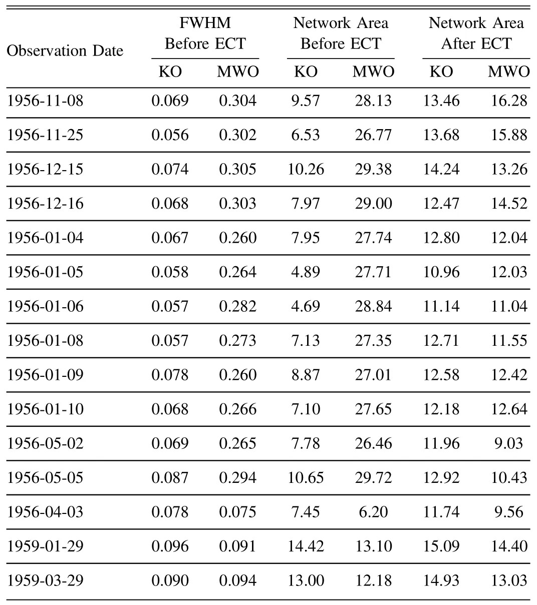
Table 3 The Values of FWHM of the Intensity Distribution before the ECT Application, QN Area for the KO and MWO Data before and after the ECT Application to the Images are Listed
The present analysis allows separating these components and showing their cycle variation directly for the first time.The fact that all active Sun components(AN,EN,QN,plage and active region) display variations in phase with sunspot number may suggest that an area that is free of the magnetic field should vary in antiphase with the sunspot cycle (or that the magnetic fields are more tightly packed together during maxima of sunspot activity as compared with periods of minima).
The slope (31.2 for KO and 31.8 for MWO) and intercept(-245 for KO and-238 for MWO)of linear regression for the scatter plot between the percentage of total small-scale features and sunspot numbers agree with each other, as indicated in Figure 7.Similarly,the slope values(27.6 and 28.4)for the KO and MLSO (PSPT) filtergrams agree, but the intercepts (-122 and -217) are different.The slope values for filtergram data are less compared to those for spectroheliograms.This might be because the sunspot numbers are different for the spectroheliogram and filtergram observing periods.The maximum sunspot number during spectroheliogram observations(1905–1997) is around 450 compared to ≈350 during filtergram observations (1997–2015).The scatter plots for spectroheliogram indicate a tendency for%EN area not to vary with sunspot number >250.This can cause a difference in slope values.This can also be due to the broader passband of the filtergrams compared to that for spectroheliograms and different spatial resolutions.More sets of filtergram data with different specifications observed during the same period need to be analyzed to determine the reason for the differences.
Considering the average normalized intensity of network features and variation in their areas,on average 3%variation in the Ca-K flux occurs due to small-scale elements during a solar cycle.It may be noted that the total area occupied by the Ca-K features, representing a small-scale magnetic element, varies from 5% to 20% on the solar disk between the minimum and maximum phase of the solar cycle when considered on a daily basis.There can be two reasons for this increase.One,the Ca-K network size becomes smaller at the maximum phase as found by Singh&Bappu(1981),Pevtsov et al.(2016).They reported that cell size is ≈5%smaller at the maximum phase than at the minimum phase.This can lead to the larger area being occupied by the network boundaries.
Variations in size of the supergranulation were reported by several studies(for review,see:Rincon&Rieutord 2018)with somewhat contradictory results.Most studies (e.g., Singh &Bappu 1981) found an anti-correlation with the solar cycle.Some other studies found the opposite correlation (e.g., Wang&Shi 1988;Muenzer et al.1989;Meunier et al.2008).Tlatov(2012)reported a cycle variation in size of the supergranulation with a small phase shift with respect to the sunspot cycle.The phase shift was about 1.5 yr, with minima/maxima in the size of the supergranulation occurring after sunspot minima/maxima.Pevtsov et al.(2016) analyzed the annual mean spatial scales detected through a periodogram analysis and found less than 5% variations over a solar cycle, comparable with the scatter in data.Another reason may be that the magnetic field becomes stronger at the boundaries of a network at the maximum phase compared to that at the minimum phase.This can increase the brightness of the network boundaries during the maximum phase.Therefore,more network areas are detected during the maximum phase.It may be noted that the boundaries of the network are not uniformly bright.The brightness of the portion of the boundary depends on the underlying magnetic field.
In summary, we can say that the ECT methodology improves the uniformity of Ca-K images taken over a long time with different instruments to generate an extended series to study longterm variations on the Sun.The use of ECT has enabled us to reliably investigate the systematic variations in the small-scale Ca-K features,and thereby the magnetic elements.The results of this study will help to make realistic modeling of irradiance and understand the dynamics of the Sun.
Acknowledgments
We thank the reviewer for useful comments,which helped to improve the content of the paper.We thank the numerous observers who made observations, and maintained the data at KO and MWO.We also thank the digitization teams at KO(Founder PI, Jagdev Singh) and MWO.The high spatial resolution Ca-K data were downloaded from Stanford Helioseismology Archive—prog:mwo (http://sha.stanford.edu/mwo/cak.html).The Precision Solar Photometric Telescope was maintained and operated at Mauna Loa Solar Observatory from 1998 to 2015 by HAO/NCAR.The data were processed and are served to the community by the Laboratory for Atmospheric and Space Physics, University of Colorado,Boulder (http://lasp.colorado.edu/pspt_access/).The sunspot data are from the World Data Center SILSO, Royal Observatory of Belgium, Brussels.The National Solar Observatory (NSO) is operated by the Association of Universities for Research in Astronomy (AURA), Inc., under a cooperative agreement with the National Science Foundation.Observations at the Mount Wilson Observatory have been supported over the years by the Carnegie Institute of Washington, the National Aeronautics and Space Administration,the US National Science Foundation and the US Office of Naval Research.L.B.and A.A.P.are members of the international team on Modeling Space Weather And Total Solar Irradiance Over The Past Century supported by the International Space Science Institute (ISSI), Bern, Switzerland and ISSI-Beijing, China.
杂志排行
Research in Astronomy and Astrophysics的其它文章
- Period Investigation on Two W UMa Binaries HH UMa and V1175 Her
- Influence of Solar Activity on Precise Orbit Prediction of LEO Satellites
- Constraining the Temperature-density Relation of the Inter-galactic Medium from Analytically Modeling Lyα Forest Absorbers
- 3D Kinematics of Classical Cepheids According to GaiaEDR3 Catalog
- Photometric Monitoring of Blazar 3C 66A with the Yunnan University Astronomical Observatory 1m Telescope
- The Variability and Radial Velocity of Planetary Nebula Central Stars
