Proportion Integration Differentiation (PID) Control Strategy of Belt Sander Based on Fuzzy Algorithm
2023-05-18CHENKunZHANGYawei张亚伟ZHANGZhenGUIZhiwei桂志伟
CHEN Kun(陈 坤), ZHANG Yawei(张亚伟), ZHANG Zhen(张 振), GUI Zhiwei(桂志伟)
College of Mechanical Engineering, Donghua University, Shanghai 201620, China
Abstract:Aiming at solving the problems of response lag and lack of precision and stability in constant grinding force control of industrial robot belts, a constant force control strategy combining fuzzy control and proportion integration differentiation (PID) was proposed by analyzing the signal transmission process and the dynamic characteristics of the grinding mechanism. The simulation results showed that compared with the classical PID control strategy, the system adjustment time was shortened by 98.7%, the overshoot was reduced by 5.1%, and the control error was 0.2%-0.5% when the system was stabilized. The optimized fuzzy control system had fast adjustment speeds, precise force control and stability. The experimental analysis of the surface morphology of the machined blade was carried out by the industrial robot abrasive grinding mechanism, and the correctness of the theoretical analysis and the effectiveness of the control strategy were verified.
Key words:grinding mechanism; constant force control strategy; fuzzy control; proportion integration differentiation (PID)
Introduction
As an important means of reducing the surface roughness of the workpiece and controlling the material removal rate, grinding plays a vital role in many fields including aerospace, vehicles, ships,etc. At present, manual grinding is still adopted in many factories in our country[1], and it is rather primitive. Manual grinding has advantages such as good flexibility and small space for production processing. However, with the progress of science and technology, the workpiece processing is more complex. The demand for grinding efficiency and precision is increasing. Manual grinding might not be able to meet the majority of grinding production demand[2]. Compared with traditional manual grinding, precision grinding and robotic grinding have many advantages such as high rigidity, good flexibility, large working space and high efficiency[3]. Industrial automatic belt grinding and polishing[4]are irreplaceable in turbine blade processing because both grinding and polishing are considered. However, it is difficult to control the stiffness of the end processing of the industrial robot belt grinding device. Therefore, it is difficult to achieve high precision and fast response of the end tool with constant force output in any working space[5].
In response to the above problems, the most widely used approach is to install active compliance devices on the robot or belt sander to achieve constant force control at the end of the process[6]. The most representative one is the proportion integration differentiation (PID) control strategy based on the pneumatic servo system[7]. However, traditional PID control is often only applicable to stable environments with a definite mathematical model and few external disturbances. In actual industrial production, the mathematical model of the control object is usually nonlinear and difficult to determine, and there are many external disturbances. Thus it is necessary to optimize and innovate the traditional PID control. Bhookyaetal.[8]used the multi-objective gray wolf optimization (MGWO) algorithm in Matlab to optimize the proportional coefficient, the integral coefficient and the differential coefficient of PID controller parameters. Heetal.[9]designed a back propagation PID (BP-PID) controller that achieved self-tuning of PID parameters using tracking errors. Based on a honey badger algorithm (HBA) and a complementary factor integrated time absolute error (CF-ITAE) for double-loop PID attitude control of balanced robots, Linetal.[10]proposed a complementary factor HBA. which solved the difficult problem of parameter tuning. Pereiraetal.[11]proposed a new fractional PID controller topology for the control of boost type DC-DC converters with minimum over/under tuning. Shi[12]applied the combination of a BP-PID control to a pneumatic constant force output system and carried out simulation experiments. Gaoetal.[13]proposed a control strategy combining the radial basis function (RBF) neural network monitoring the contradiction among response speeds, overshoot, and system stability during PID control. Qi[14]studied RBF neural network PID closed-loop control of active compliance devices of industrial robots based on the pneumatic servo system, and conducted simulation and test. Compared with BP networks, RBF neural networks had faster learning and convergence speeds, but RBF neural network PID controllers had problems such as larger system response oscillation and slower response speeds in servo system control. Songetal.[15]designed a closed-loop control system based on fuzzy PID to solve the problem of poor uniformity of solid fertilizer dissolving devices due to the lag of fertilizer dissolution. According to the test results, the fertilizer concentration regulation model was established. Zhangetal.[16]proposed a control strategy that integrated fuzzy control with PID. Compared with RBF neural network PID control, fuzzy PID control can guarantee a sensitive response with very high accuracy in a very short time. Fuzzy control has high adaptability, so it does not need accurate mathematical modelling, and is suitable for the pneumatic servo system. Therefore, the fuzzy PID control system is chosen to ensure accurate and real-time control of the grinding force of the grinding mechanism.
In this paper, the active compliance device of a new type belt sander is taken as the research object, and the mathematical model of the pneumatic servo system is established according to the dynamic characteristics of its working process. The control strategy combining fuzzy control and PID is applied. By designing the fuzzy controller, the fuzzy rule table and membership function are established. The system is simulated and tested.
1 Control Design
1.1 Design of grinding mechanism
The grinding mechanism includes driving wheels, tensioning cylinders,etc. whose basic function is to maintain the operation of the abrasive belts. In order to realize the precise control of the grinding force, we need to optimize an grinding mechanism[17]. The sketch of the grinding mechanism is shown in Fig. 1. The servo motor drives the driving wheel through the belt, which in turn drives the grinding belt movement. The tensioning cylinder gives the belt a tightening force to ensure that the belt does not slide relative to the wheel when working. The grinding mechanism controls the signal of the applied electromagnetic pressure valve, which in turn controls the position of the sanding point and the amount of the grinding force. The grinding mechanism and the tensioning cylinder use a closed-loop system, which can change the applied force in real-time through feedback to ensure the accuracy of grinding. The wheel system consists of a driving wheel, a contact wheel, a tensioning wheel,etc. The driving wheel provides the power for the belt rotation. The contact wheel is the wheel directly involved in sanding at the sanding point, and the belt exerts pressure through the contact wheel to sand the workpiece. The tensioning wheel is used with the tensioning cylinder to provide the tensioning force. There are three sensors installed on the compliant cylinder: a force sensor which reflects the output force of the compliant cylinder; a displacement sensor which reflects the amount of displacement change of the compliant cylinder; an angle sensor which reflects the angle change of the rotation of the active compliance device. Among them, the force sensor connects to the amplifier and then communicates with a programmable logic controller (PLC) to realize the real-time adjustment of the grinding force. After connecting the amplifier, the displacement sensor and the angle sensor communicate with the Labview software to obtain input and output data of the system so as to facilitate the identification experiment later.

Fig. 1 Sketch of grinding mechanism
The mathematical modelling process of the aerodynamic servo system of the active compliance device is based on the hypothesis of small disturbance linearization, which simplifies many factors. Moreover, it is difficult to determine some parameters of many components in the pneumatic circuit, which leads to a large deviation between the mathematical model and the actual system. So we need to analyze the control part of the active compliance device.
From Fig. 2, the operation of the grinding mechanism mainly includes the following stages. (1) After ventilation, the upper computer sends a voltage signal through the PLC to make the tensioning cylinder tighten. (2) The upper computer sends a drive signal through the PLC to make the servo motor rotate. (3) The upper computer sends a voltage signal through the PLC to control the compliant cylinder and then control the grinding head to swing back and forth according to the established route to polish the workpiece. (4) The force sensor, the angle sensor, and the displacement sensor are used to collect the feedback data of the grinding mechanism. The controller receives the signals from three sensors and processes the data in time, and then makes feedback adjustments to the system in real-time, so as to achieve the fast response and dynamic stability of the grinding force. The sensor signals are fed back to the data acquisition module of the controller in real-time, and the data acquisition module is fed back to the grinding mechanism after appropriate adjustment of parameters by the fuzzy PID closed-loop control algorithm. It is calculated that the variation of the belt length during the working process is almost negligible compared with the total length of the belt. The analysis of the grinding process shows that the grinding force has a great influence on the surface quality of the workpiece and it is very easy to produce oscillation. Thus the constant force control strategy of the grinding force plays a vital role in the stable operation of the grinding mechanism.
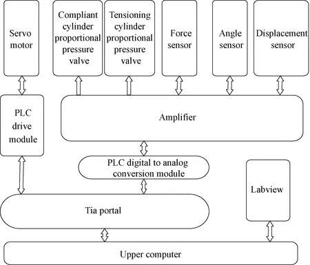
Fig. 2 Control system structure diagram
1.2 Force control condition determination
The working condition of the grinding mechanism during the actual grinding process is shown in Fig. 3. The grinding mechanism deflects the angleαcounterclockwise during the actual grinding process, and the value ofαchanges continuously[18]. There is a relationship between the grinding force and the compliant cylinder. The motion of the grinding mechanism was simulated by the Motion plug-in in the SolidWorks software. The motion trajectory was obtained from the image recognition, the motion parameters were added to the simulation, and the range ofαduring the grinding process was -15.64°- 74.36°. The force of the grinding mechanism is shown in Fig. 4.
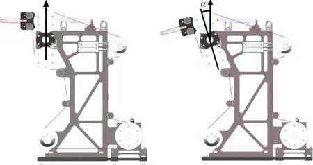
Fig. 3 Schematic of grinding mechanism: (a) initial position; (b) operating position

Fig. 4 Force diagram of grinding mechanism
According to the moment balance
(1)

The length of each other line segment is determined under the condition that the grinding mechanism structure is determined. The range of the force to be applied by the grinding mechanism is 167.177- 401.046 N.
1.3 Pneumatic servo system mathematical model
The pneumatic servo system takes the output force of the compliant cylinder as the control object, and includes an air source, a solenoid pressure valve, a compliant cylinder, a displacement sensor, a force sensor, an angle sensor, an amplifier, Siemens PLC, an upper computer,etc. It is a closed-loop control system with the existence of signal feedback.
Since there are too many factors affecting the motion characteristics of the belt sander in practical applications, the following assumptions are made to reflect the influence of the studied parameters on the grinding forces of the grinding mechanism and to establish a simplified mathematical model by ignoring minor factors.
The total model of the pneumatic servo system is
(2)
whereεnis the system damping ratio;Knis the system amplification factor;ωnis the system natural frequency.
The mathematical model of the pneumatic servo system shown in Eq. (2) is a simplified mathematical model excluding minor factors. Since it is difficult to determine the parameters of many pneumatic components in the system, there is a big gap between this model and the actual mathematical model. In order to improve the accuracy of the system, the model of the system is carried out by the Matlab-based system model identification method. Import input and output, and generate the file name tf1 of the mathematical model data.
The obtained mathematical model for identification is
(3)
1.4 Fuzzy PID controller design
1.4.1ClassicalPIDcontroller
The block diagram of a classical PID controller is shown in Fig. 5.

Fig.5 Block diagram of classical PID controller
The classical PID controller is a linear control algorithm[19], the system input and the system output are in(t) and out(t), respectively, and the expression of its deviatione(t) is
e(t)=out(t)-in(t).
(4)
The expression of the transfer function of the classical PID controller is
(5)
(6)
whereKp,KiandKdare proportional, integral, and differential time constants of the PID control algorithm, respectively.
1.4.2FuzzyPIDcontroller
The block diagram of the fuzzy PID controller is shown in Fig.6.
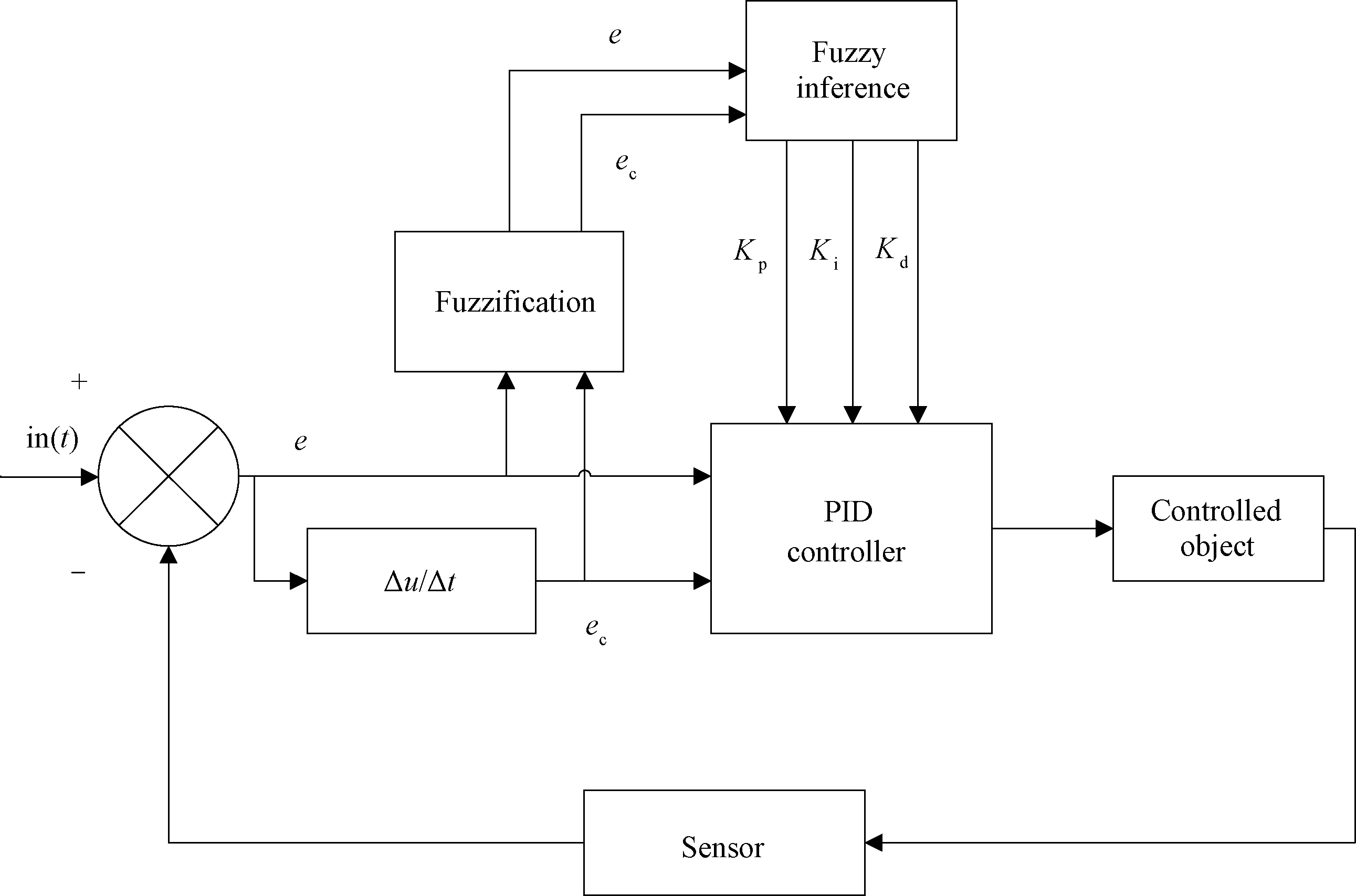
Fig. 6 Block diagram of fuzzy PID controller
It can be intuitively seen that the fuzzy PID controller has an additional fuzzy control part compared with the traditional PID controller. Its general working process is as follows. Firstly, the deviation and the change rate of the variables are input to the controller, then three PID parameters are adjusted using fuzzy rules, and finally a stable output is obtained[20]. The editing of the fuzzy rules and the adjustment of the parameters are the keys to designing a fuzzy PID controller.
In this paper, the input deviationeand the deviation change rateecare quantified once by the quantization factorsKeandKec, and the output quantities ΔKp, ΔKiand ΔKdare scaled once by the defuzzification scale factorsKp,KiandKd. The input deviationeand deviation change rateecare taken, and ΔKp,ΔKiand ΔKdare fuzzy subsets {NB, NM, NS, ZO, PS, PM, PB}, where NB, NM, NS, ZO, PS, PM and PB represent negative big, negative medium, negative small, zero, positive small, positive medium and positive big, respectively. The theoretical domain is {-3, 3}, and the quantization levels are {-3, -2, -1, 0, 1, 2, 3}. The membership function curves of the system are shown in Figs.7 and 8.

Fig. 7 e and ec membership functions

Fig. 8 ΔKp, ΔKi and ΔKd membership functions
According to the role ofKp,KiandKd, the interconnection relationship between three parameters, and the influence on the output characteristics, the self-tuning requirements ofKp,KiandKdcan be summarized. The fuzzy rules can be obtained as Table 1.
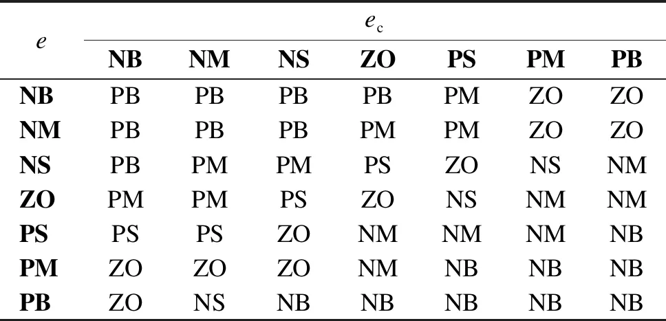
Table 1 Fuzzy rule table
The above 49 fuzzy rules form a fuzzy rule matrix, and the fuzzy output quantity is decided according to the fuzzy input quantity.
The final control parameters of the systemKp,KiandKdare found by
(7)
whereKp0,Ki0andKd0are the initial PID values.
1.5 Matlab/Simulink simulation
Enter fuzzy in the Matlab window, open the fuzzy control toolbox, and use the Simulink fuzzy logic toolbox to establish the affiliation function of each variable. Input and output signal subsets are {NB, NM, NS, ZO, PS, PM, PB}, the input signalseandecare chosen to be Gaussian functions, and the affiliation functions of the system output signals ΔKp, ΔKiand ΔKdare triangular functions that are uniformly distributed in the theoretical domain and have high sensitivity. After setting the parameters of the fuzzy control toolbox, the control system model shown in Fig.9 is established in the Matlab/Simulink simulation environment. The system includes fuzzy inference machine, a PID controller and a feedback module.
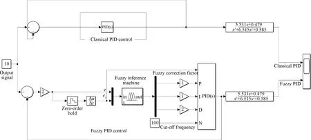
Fig. 9 Matlab simulation flow chart
2 Results and Discussion
2.1 Simulation result
The output force of the compliant cylinder is 10 N; the running cycle is 4.000 s. The final simulation results are shown in Fig. 10. The analysis of the system response diagram shows that compared with classical PID control, the system adjustment time of fuzzy PID control is reduced by 98.7%, up to 45 ms, the system response overshoot is reduced by 5.1%, and the control error after system stabilization is 0.2%-0.5%. Compared with classical PID control, the response time of fuzzy PID control is greatly reduced. The simulation proves that the system has very good stability, adaptability and robustness in theory.
2.2 Test results
The grinding mechanism shown in Fig. 11 is used to verify the reliability of the fuzzy PID control strategy.
In the grinding process, because the processing surface of the blade is irregular, and the oscillation angle of the grinding rod is very limited by the influence of the structure, the simple rotation of the blade cannot meet the processing requirements of the whole processing surface. By using the SolidWorks software to simulate the motion parameters of the blade and the grinding mechanism, it is found that the motion iteration is very complicated and it is difficult to ensure the stable processing state of the blade and the grinding mechanism. Therefore, the technology of laser scanning and image processing was adopted to optimize the algorithm of motion trajectory of the ABB(Asea Brown Boveri) robot and the grinding mechanism. The optimized motion parameters were imported into the PLC, and the PLC controlled the ABB robot and the compliant cylinder to move according to the planned path so as to realize the grinding process of the blade. The workpiece was held by the ABB robot the ABB robot has perfect performance and high precision, and can realize precise control of the blade[21]. The picture of grinding unit is shown in Fig. 12.
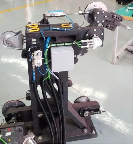
Fig. 11 Grinding mechanism
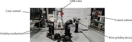
Fig. 12 Grinding unit
The fuzzy PID control was input to the controller and applied to the grinding unit to get the finished blade, and then the surface roughness of the blade was analyzed.
It is known from Fengetal.[22]that the belt wheel line speed is the test factor that has the most significant effect on the roughness and the surface topography of the grinding workpiece. Thus the belt wheel line speed was chosen as a univariate variable for the abrasive belt grinding and polishing test. The grinding areas at different abrasive belt line speeds are shown in Fig.13. The grinding area was divided into three groups with 1, 2 and 3 marked on the blade. We take three points from each group and calculate the average. The blade roughness is measured using a white light interferometer shown in Fig.14 with the process parameters shown in Table 2.
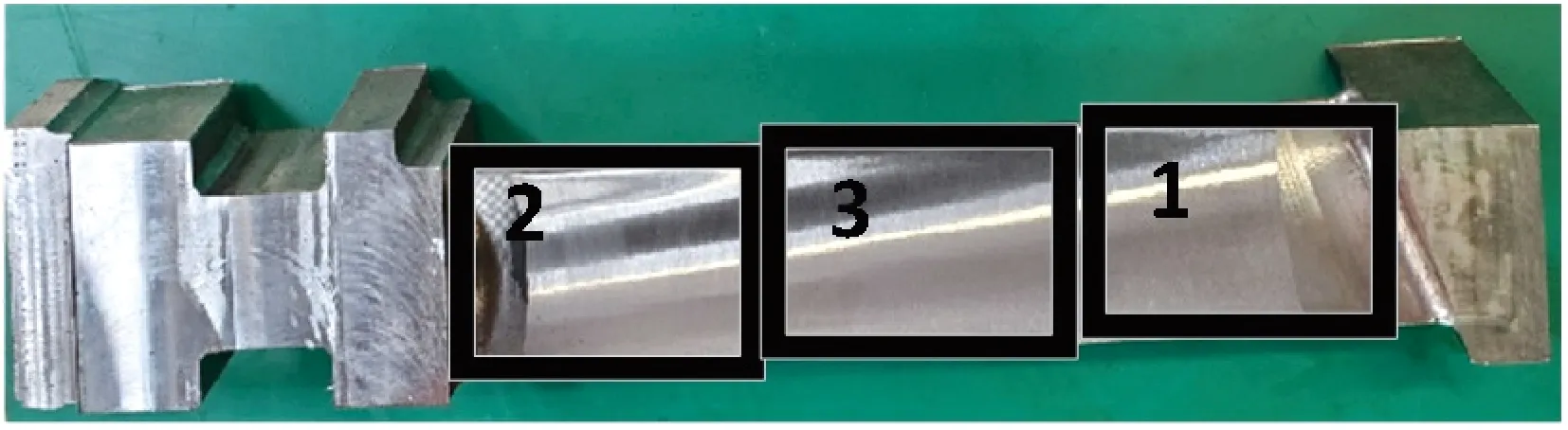
Fig. 13 Grinding area
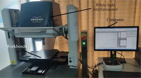
Fig. 14 White light interferometer measurement platform

Table 2 Belt grinding test process parameters
The model white light interferometer was used to measure the roughness of three grinding areas of the blade respectively. The roughness measurement values are shown in Table 3.
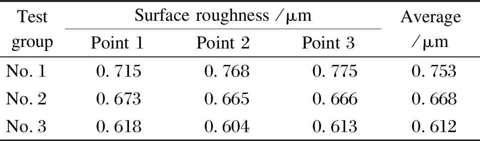
Table 3 Surface roughness of blades
It can be seem from Table 3 that the surface roughness of the blade processed by the fuzzy PID control meets the quality requirement of the specified surface roughness(lower than 0.800 μm).
3 Conclusions
According to each signal transmission process of the grinding mechanism and the dynamic characteristics of the belt sander at work, a constant force control strategy combining the fuzzy control algorithm and PID was proposed.
Simulation and analysis results of classical PID control and fuzzy PID control show that under fuzzy PID control, the system adjustment time is 45 ms, and the system response overshoot is small. In addition, the control error after the system is 0.2%-0.5%, which meets the technical requirements of the project.
The practical analysis verifies the feasibility of grinding under the fuzzy PID control strategy. The surface roughness of the blades at different linear velocities was lower than 0.800 μm and reached the quality requirement.
杂志排行

Journal of Donghua University(English Edition)的其它文章
- Simultaneous Morphologies and Luminescence Control of NaYF4∶Yb/Er Nanophosphors by Surfactants for Cancer Cell Imaging
- Porous Graphene-Based Electrodes for Fiber-Shaped Supercapacitors with Good Electrical Conductivity
- Fabrication of High-Efficiency Polyvinyl Alcohol Nanofiber Membranes for Air Filtration Based on Principle of Stable Electrospinning
- Construction of Oriented Structure in Inner Surface of Small-Diameter Artificial Blood Vessels: A Review
- Auto-Generation Method of Child Basic Block Structure
- Small Amplicons Mutation Library for Vaccine Screening by Error-Prone Polymerase Chain Reaction