Dynamic Frontier-Led Swarming: Multi-Robot Repeated Coverage in Dynamic Environments
2023-03-27VuPhiTranMatthewGarrattKathrynKasmarikandSreenathaAnavatti
Vu Phi Tran, Matthew A.Garratt,, Kathryn Kasmarik,, and Sreenatha G.Anavatti
Abstract—A common assumption of coverage path planning research is a static environment.Such environments require only a single visit to each area to achieve coverage.However, some real-world environments are characterised by the presence of unexpected, dynamic obstacles.They require areas to be revisited periodically to maintain an accurate coverage map, as well as reactive obstacle avoidance.This paper proposes a novel swarmbased control algorithm for multi-robot exploration and repeated coverage in environments with unknown, dynamic obstacles.The algorithm combines two elements: frontier-led swarming for driving exploration by a group of robots, and pheromone-based stigmergy for controlling repeated coverage while avoiding obstacles.We tested the performance of our approach on heterogeneous and homogeneous groups of mobile robots in different environments.We measure both repeated coverage performance and obstacle avoidance ability.Through a series of comparison experiments, we demonstrate that our proposed strategy has superior performance to recently presented multi-robot repeated coverage methodologies.
I.INTRODUCTION
MANY recent coverage algorithms assume a static environment, necessitating only a single visit to each area of the environment to deem that the area is“covered”.Examples include frontier-based methods [1], [2], graph-based approaches [3], min-weighted rigid graph [4], geometric flight patterns [5], next best view (NBV) algorithms [6], and deep learning [7].However, certain real-world applications require that areas of the environment be revisited periodically.This includes applications such as security patrols, or applications in dynamic environments, where revisiting is necessary to maintain an accurate coverage map [2], [8].To date, relatively little work has been done on such“repeated coverage”problems in environments with unexpected, dynamic obstacles.The work in this paper addresses this dual gap of repeated coverage in the presence of dynamic obstacles.
Environments with unexpected, dynamic obstacles pose a novel challenge for coverage algorithms because successful solutions must combine elements of exploration, repeated coverage, and reactive obstacle avoidance in a single system.This problem is more challenging to solve with multi-robot teams,due to the additional need for formation control and coordination.Multi-robot teams have an advantage over single robot systems because they incorporate redundancy.However, the interplay of components for exploration, coverage, obstacle avoidance and formation control poses significant challenges to the performance of each individual subsystem.This calls for novel solutions to optimise the performance of the system as a whole.The contributions of this paper are:
1) A novel problem definition for repeated coverage in environments with initially unknown, dynamic obstacles.We also present a suite of metrics for evaluating the different facets of this problem, including metrics for repeated coverage, obstacle avoidance and formation quality in a multi-robot setting.
2) A novel algorithm for solving this problem.Our proposed approach combines frontier-led swarming for multirobot exploration with pheromone-based stigmergy for repeated coverage and obstacle avoidance.Two variants of our base algorithm are presented, the first using a single, fixed rate of coverage repetition and the second using multiple rates of coverage repetition to prioritise different regions of the environment.
3) An experimental investigation of algorithms for solving the repeated coverage problem in different environments.We compare our approach against metrics for coverage, obstacle avoidance and formation control.
The fundamental framework underlying the solution presented in this paper is a swarm intelligence system.Swarm intelligence offers a range of techniques inspired by natural systems for the control of a cooperative multi-robot system to obtain ordered and intelligent behaviors [9].In this paper we combine collective motion rules for formation control, and pheromone-based stigmergy for communication, coordination and obstacle avoidance.
The next sections proceed as follows.In Section II, we begin with formal problem definition and a literature review of related papers, including the necessary background to provide the foundation for the current paper.Our algorithm for repeated coverage in dynamic environments is introduced in Section III.Experimental work is presented in Section IV.Finally, conclusions are presented in Section V.
II.PROBLEM DEFINITION, BACKGROUND AND RELATED WORK
In this section we first introduce the underlying mission we are addressing in Section II-A: repeated area coverage in a dynamic environment, including relevant definitions from the literature.We then review existing challenges in fundamental areas that must be combined to solve the problem presented in this paper.In Section II-B we examine frontier-based approaches to exploration, and in Section II-C we examine stygmergy-based approaches to multi-robot coverage.In Section II-D we examine dynamic obstacle avoidance.Finally we introduce the boid model from the literature that underlies our combined solution in Section II-E.
A.Area Coverage Problems
Area coverage requires a group of agents or robots to visit every position in an environment.Typical real-world examples include vacuum cleaning, painting and lawn mowing.To formally define the coverage problem a grid discretisation of space is generally first defined with a certain resolution.Grids can be of different shapes including cells with triangular,square, hexagonal or diamond shapes [10].Square grids are used in this paper since they are commonly used in geographic information system (GIS) mapping.This is because they are simple to define and store and the relationship between cells can be calculated at a low computational cost.
Different definitions of coverage of the grid exist, including dynamic coverage and static coverage [5].In static coverage[11], agents need to seek out optimal locations that form an appropriate geometry so that their network of sensors can observe the whole environment.However, in some practical missions, the environment cannot be fully observed by a static coverage network due to limitations in sensing ranges or too few sensors being available.In such cases, the problem of
dynamic coverage is considered.
With dynamic coverage, mobile robots with limited-range sensors continuously move and sample data, from spaces within a discretized domain until a predefined coverage level is attained.Often this coverage level is defined as visiting each space exactly once.In this paper, we focus on the dynamic coverage problem, with the further specification that each space must be repeatedly revisited as frequently as possible.We call this the repeated coverage problem.We assume in this paper that the size of the environment to be covered is known in advance.However, the locations of any potential obstacles are not known in advance.In addition, the positions of these obstacles can change over time.
In a simple formal definition of repeated coverage, the obtained coverage information can be either direct and indirect:
Definition 1:A 2D grid celljis covered by agentAiifAiwas within celljat some point during the exploration.In that case, we say thatAihas directly covered cellj[12].
Definition 2:In a multi-agent system, if agentAicommunicates the coverage of celljto a neighbour agentAk, we say that agentAkhas indirectly covered cellj.
Definition 3:Synchronised coverage is achieved in a multi-agent system when each agent has directly or indirectly covered all grid cells of the map.In other words, each agent knows that each cell has been directly covered by either itself or some other agent.
Collaborative, complete exploration and coverage are two active research fields, where multi-robot systems are required to maintain situational awareness in unknown obstacle-cluttered scenarios.Solving these problems can benefit many potential applications, including environmental waste management [13] and search and rescue [14].
Several recent studies have considered repeated coverage.For example, [15] guarantees full awareness coverage when revisiting all points periodically.In [16], mobile robots are driven to the centroid positions of the Voronoi cells that maximize the visual field, meaning that multi-robot optimal coverage is obtained through time-varying density functions.In contrast to the work in this paper, each agent independently performs area coverage.In our work, we focus on groups of agents patrolling together in a dynamic environment.
In the following sections, we consider existing work on the components required to achieve these goals.
B.Frontier-Based Approaches to Exploration
Frontier-based algorithms have been shown to achieve high performance in terms of precision and efficiency for map exploration [17] and coverage [18].These algorithms search for frontier regions, defined as the boundaries between explored and unexplored areas, to guide an individual or a group of agents [19].The low exploration time and reduced computational cost of frontier-based methods have been reported in various studies [20].

The foundations of frontier-based exploration are the occupancy grid mapping technique [21].A global occupancy grid map (M), is a discretized representation of the environment where each cell possesses an occupancy value of 0 for unexplored, 1 for explored, and 2 for obstacle, respectively.withJfis the number of cells in the frontierFf.Each robot approaches its nearest navigation goal point, senses new regions of the map, and broadcasts its results.The associated frontier is then extracted from the frontier list.The size of the explored environment increases by repeating this operation until the whole environment has been visited.
While frontier-based algorithms are usually applied to exploration, they have been applied to (single visit) coverage problems [2].We build on such an approach in this paper to solve repeated coverage problems in the presence of unknown, dynamic obstacles.To address the challenge of dynamic environments, we adopt a stigmergy approach.This concept and related work is introduced in the next section.
C.Stigmergy-Based Approaches to Multi-Robot Coverage
Stigmergy is a method of indirect interaction between one or more individuals by registering a trace or signal in a specific location in the environment.Once the receptive organ of an individual in the swarm senses such a signal, an action is stimulated accordingly.
Distributed virtual pheromone systems for swarm area coverage have been used in previous studies [22].Those methods include the ant colony optimisation (ACO) method [23], and bee colony optimisation (BCO) [24].Ranjbar-Sahraeiet al.[25] introduced a pheromone-based area coverage method called StiCo, which allows coordination among multiple robots without requiring a priori information on the environment.Similarly, another multi-robot coverage solution, named BeePCo, is based on honey bee colony behavior [26].
Instead of virtual pheromones for a collective task, a repulsive pheromone-based model to adjust the agents’behaviours was introduced by Kuiper and Nadjm-Tehrani [27].Agents share a centralized memory where a map of virtual pheromones is stored.The agents have a tendency to move to locations where lower pheromone levels are detected.A similar approach is taken in.We will use this approach as a comparison in our current paper.
Other multi-pheromone systems have also been considered.For instance, in the ant food recruitment task, at least three kinds of pheromones are considered [28].In a collective smart scheme, attractive and repellent pheromones are involved[29].In this paper we adopt a multi-pheromone approach to control repeated coverage and obstacle avoidance.We examine existing approaches to obstacle avoidance in the next section.
D.Obstacle Avoidance Algorithms
In order to navigate through a cluttered environment without collision, a simple approach is to steer the robots directly into a safe area.Lee and Chwa [30] addressed this challenge by measuring distances between an agent and surrounding obstacles and other robots, given an array of ultrasonic sensors arranged in a ring.A safe rotation angle for each robot is computed as a function of its orientation towards the target direction and its relative position with respect to the obstacles or other robots.In another work [31], the authors developed an obstacle avoidance strategy for intelligent robotic swarms using a geometric obstacle avoidance control method(GOACM).This method employs navigation planning for a leader, while followers establish a safe formation with regard to the leader.In this paper, we propose an approach in which all agents can perform obstacle avoidance, so no leader is required.
Other potential solutions to the dynamic obstacle avoidance problem for multi-agent formations include reinforcement learning [32], artificial potential fields (APFs) [33], fuzzy control [34], and prediction-based safe path planning [35].Deep reinforcement learning-based obstacle avoidance strategies improve their performance through learning, but require offline training to do so.Despite the ease of implementation and well-structured mathematical foundations, it is a challenge for this method to overcome local minima when moving near obstacles or through a narrow pathway between obstacles [36].Furthermore, the prediction model to estimate moving obstacles’future trajectory depends on assumptions about the obstacles speed and direction, which are subject to multiple disturbances and uncertainties [37].
Mobile obstacles considered in recent studies often possess a fixed size and velocity [38].However, the center of an obstacle is difficult to determine in real applications, and sensors do not always have the long detection range required by the Steer-to-Avoid and Negative-Imaginary avoidance algorithms [39]−[42].In this paper, we propose a novel obstacle avoidance approach designed specifically for a reactive, frontier-led swarming setting.In the next section, we introduce the swarming fundamentals used in our approach.
E.Artificial Swarming Behavior
Existing works have considered the use of swarming behaviours in coverage to maintain a close-knit formation to facilitate short-range communication during the coverage process [2], [43].This paper augments that algorithm with pheromones to facilitate repeated coverage and dynamic obstacle avoidance.We begin the next section with a description of the boid-swarming algorithm that underlies our approach before presenting the details of our algorithm.
III.DYNAMIC FRONTIER-LED SWARMING
The coverage algorithm introduced in this paper, called dynamic frontier-led swarming, builds on frontier-led swarming [2].Frontier-led swarming was demonstrated to effectively solve single pass coverage but is insufficient to address rapid changes caused by moving obstacles in a cluttered environment.Digital pheromones are presented in this paper to both predict the trajectory of moving obstacles and drive repeated coverage to maintain an accurate coverage map in the presence of such obstacles.
This section is organized into five parts.Section III-A describes the underlying swarming approach used.Section III-B introduces the data structure that underlies our algorithm,called a shared pheromone coverage matrix.Section III-C introduces the frontier search process that drives exploration.Section III-D introduces the obstacle avoidance processes and their integration with swarming.Section III-E examines the time and memory complexity of these components.The nomenclature used in this section is presented in Table I.

TABLE I NOMENCLATURE
A.Swarming
This paper builds on a Boid approach to swarming [44].By applying the rules of alignment, cohesion and separation, a collective motion emerges based on the interaction of individual members of a group.These rules generate the corresponding force vectors acting on agents when a certain condition holds.Let us firstly denote a team ofNagents asAI1,AI2,...,AIN.At time indext, each agentAIilooks for all neighbours within certain radii for cohesionRc, separationRs, and alignmentRaas follows:
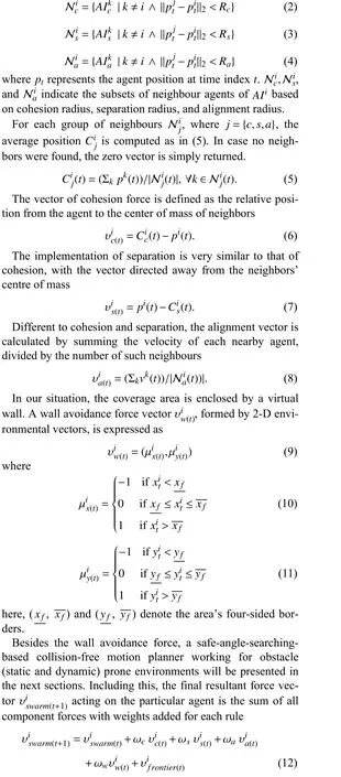
where different positive weights ωc, ωa, ωs, and ωw, are used to tune the behavior model.υifrontier(t)is the frontier search force that will be described in Section III-C and (19).vswarm(t)represents the swarming force vector accumulated over time to reduce the excessive change of the velocity vector between the timetandt+1 and make the robot movements smoother.Without force accumulation, the robot’s direction of movement constantly changes, resulting in system instability.
B.Shared Pheromone Coverage Matrix
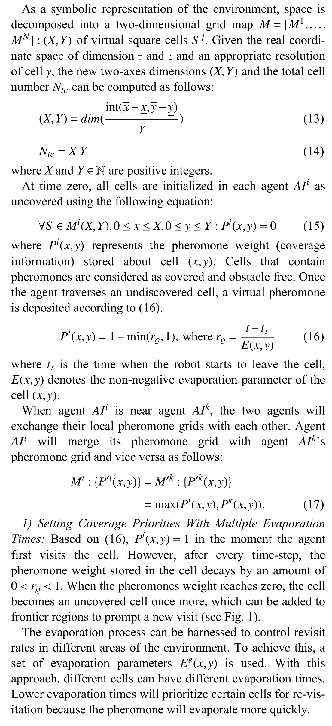

Fig.1.An illustration of decreasing pheromone concentration over time.Light blue cells have lower pheromone weights than dark blue cells.
C.Frontier-Led Swarming for Repeated Coverage
The shared pheromone coverage matrix is updated as agents traverse the environment.They traverse the environment using frontier-search.In Section II-B we presented the basic frontier search algorithm.In this paper we augment the step for selecting the closest frontierF∗with an optimisation function
where ΨDand ΨSare weights.Equation (18) is optimised when the distance traversed by the robot is short and the frontier size is large.
After the best frontier is adopted as the desired destination,the algorithm steers the relevant robot towards that region’s goal point through an attractive force.Its mathematical model is as follows:
whereGfis the position of the best frontier in theith robot’s map; υfrontierrepresents the frontier steering force.visis theithrobot’s separation force vector.Note that the separation forces only apply when two robots are within their Boidsseparation radius.
In case the same best cell is simultaneously selected by the two robots, a potential robot-robot collision can occur.To solve this issue, when two robots are closer than the critical circle radiusRs, they compute only the separation vector and neglect the frontier vector, as indicated in (19).Each robot continues exploring until a time-out condition occurs (t>Te),at which point that robot will traverse back to the home position and wait for the other robots.The next section examines how an obstacle avoidance force is incorporated with the swarming and frontier forces discussed so far.
D.Obstacle Avoidance Using Digital Pheromones
In our online obstacle displacement prediction model, an actual LiDAR sensor system is equipped on each robot to measure distances (do) and angles (α) from any surfaces.It works by emitting pulsed light waves in all directions and measuring how long it takes for them to bounce back off surrounding objects.To make things convenient for further computation, the LiDAR information chain is converted to Cartesian coordinates as follows:
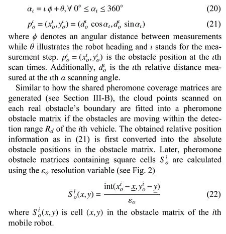
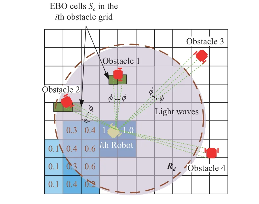
Fig.2.Obstacle grid including dark green explored-by-obstacles cells using LiDAR sensor information.
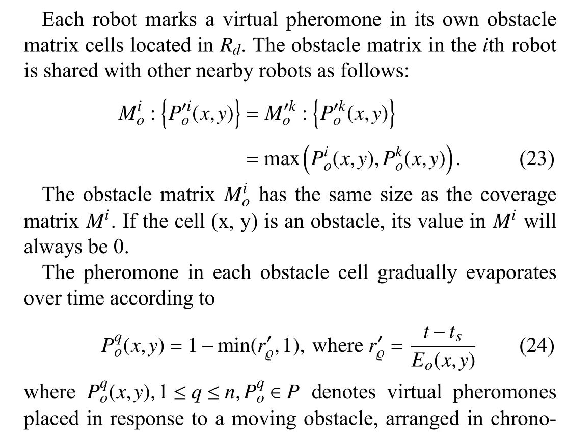

Since the physical LiDAR sensors do not determine the owner of each pheromone trail, a heuristic method of sorting the pheromone cells in descending order is proposed using the two criteria: 1) the 8-connected cell rule; and 2) the pheromone deviation between two successive square cells is lowest.For example, as shown in Fig.3, by applying the 8-connected cell rule, there are two 0.5-valued and 0.8-valued pheromone cells, which are adjacent to the relevant obstacle’s pheromone cell valued 1.0.However, the 0.8-valued cell is selected as its pheromone deviation with the obstacle cell only valued at 0.2.Repeating the process until no neighbour is found, the corresponding obstacle’s pheromone string (e.g., 1,0.8, 0.5, 0.2) can be finally reconstructed.
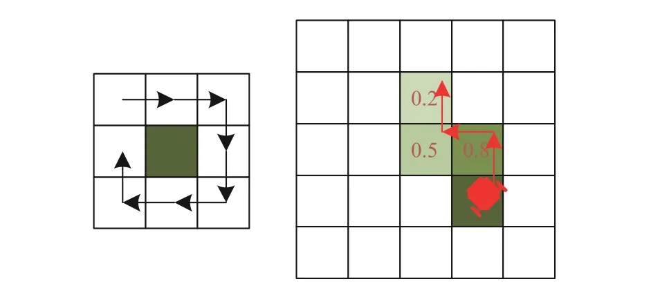
Fig.3.Past trajectory tracking method: (left) 8-Connected cell rules; (right)Example of seeking the obstacle’s pheromone path.
In the worst case, where pheromone trajectories for different obstacles are intersecting, the obstacles’history path can be inaccurately estimated.However, since the length of the pheromone strip is short, and the tracking errors between truth trail and false detection are only one or two cells, the performance of tracking the preceding dynamic obstacle motion trajectory is still satisfactory (see Fig.4).

Fig.4.Two cases of crossing pheromone paths.The yellow line represents the obstacle 1’s trajectory while the red line indicates obstacle 2’s trajectory.


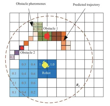
Fig.5.Predicted path of the obstacle trajectory using the pheromone evaporation strategy.The green cells represent the traveled path while the orange cells denote the future movements.

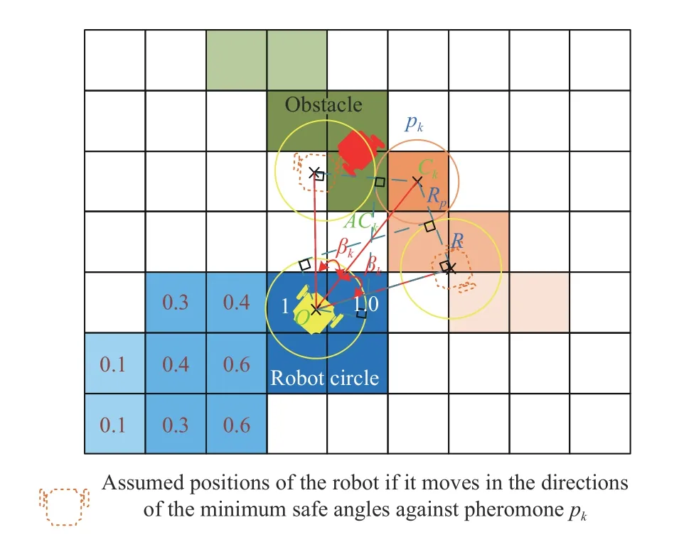
Fig.6.Illustration of robot and pheromone safety circles.
A complete list of the blocked anglesDis obtained from
Now, a list of safe anglesLcan be established by excluding the listDfrom the listα
Since the LiDAR module provides 360-degree distance detection information, there are occasional opportunities to encounter the deadlock problem, where the list of safe anglesL=∅(meaning the relevant robot’s obstacle detection radius is entirely closed by the obstacles).This can only occur if a robot enters a narrow space and its exit is blocked by other robots.If this occurs, the robot will stop temporarily until the surrounding robots move on.It is not possible for all the robots to get into a deadlock condition at the same time since at least one robot will be at the edge of the group and will be able to move into free space.After that, the neighbouring robots will be able to find safe angles of movement.Otherwise, the safe angle closest to the target angle αtis selected as follows:
The outcome of our obstacle avoidance strategy is the robot’s desired minimum orientation αr.This is incorporated with the swarming and frontier forces calculated in the previous sections to turn the robot towards the angle αrto dodge a set of the predicted obstacle cells.The resulting force on robotiis
Finally, the robot’s linear and angular velocity reference commands, namedVandωrespectively, can be calculated from thexandycomponents of the final force vector using
Pseudocode for our proposed dynamic frontier-led swarming and obstacle avoidance strategies using pheromones is given in Algorithms 1−3.

Algorithm 1 Dynamic Frontier-Led Swarming 1: Inputs: agent i, time step t.υi2: Outputs: robot velocity.GOAL=HOME3: if thenpi(t)HOME4: if location is then υi=0 5: Set 6: Keep sharing the coverage and obstacle grids using Algorithm 3HOME7: if all robots then 8: Stop the algorithm.9: end if 10: else 11: Compute the goal force 12: end if 13: elseS TOP14: if signal heard or completion time up thenGOAL=HOME15: Set 16: else υi17: Compute and update the pheromones stored in the coverage and obstacle matrices , by Algorithm 2 18: end if 19: end ifMi Mio
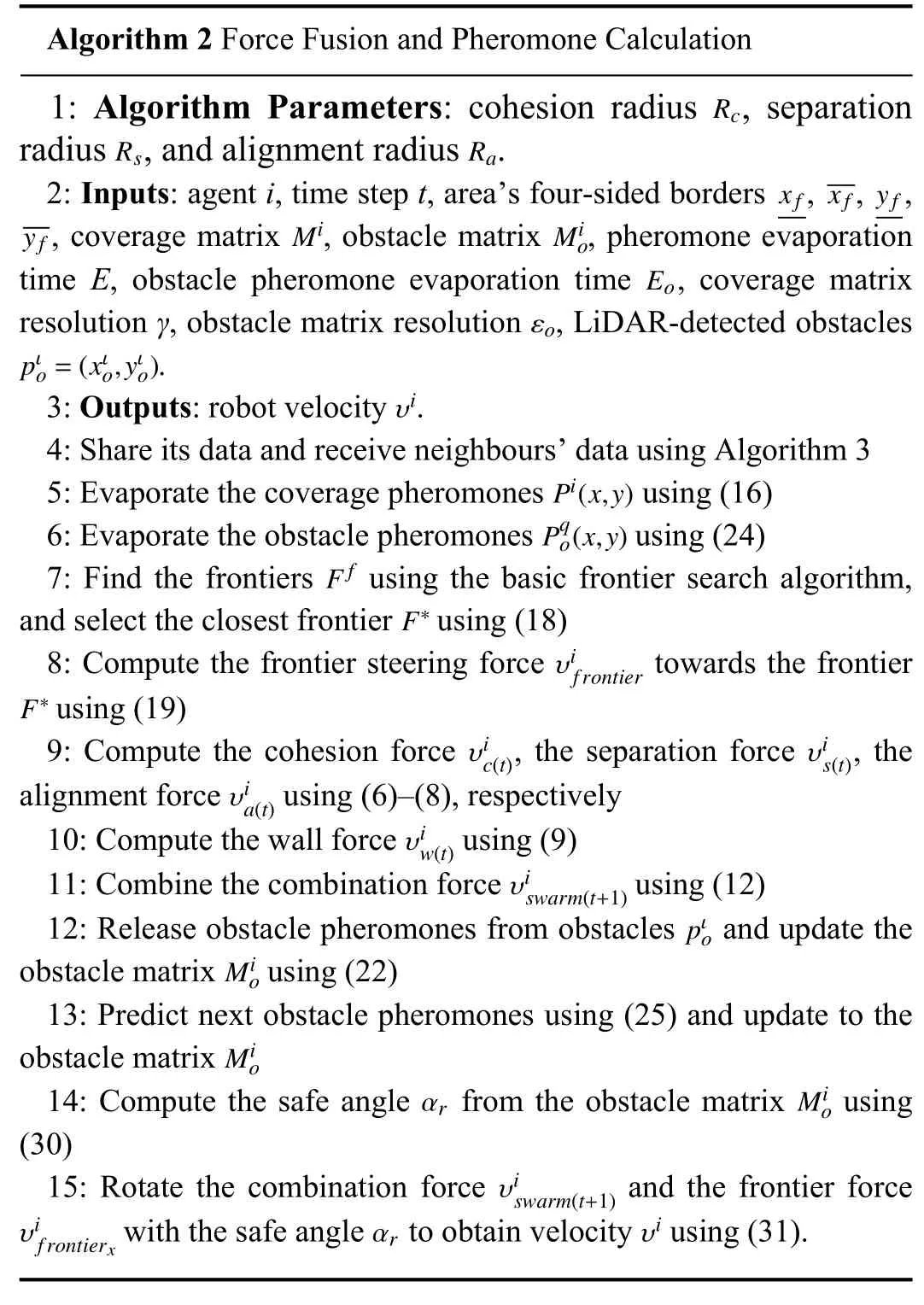
Algorithm 2 Force Fusion and Pheromone Calculation 1: Algorithm Parameters: cohesion radius , separation radius , and alignment radius.RcRsRa2: Inputs: agent i, time step t, area’s four-sided borders , , ,, coverage matrix , obstacle matrix , pheromone evaporation time E, obstacle pheromone evaporation time , coverage matrix resolution γ, obstacle matrix resolution , LiDAR-detected obstacles.xfxf yfyfMiMioEoεopιo=(xιo,yιo)υi3: Outputs: robot velocity.4: Share its data and receive neighbours’data using Algorithm 3Pi(x,y)5: Evaporate the coverage pheromones using (16)Pqo(x,y)6: Evaporate the obstacle pheromones using (24)Ff7: Find the frontiers using the basic frontier search algorithm,and select the closest frontier using (18)F∗υifrontier F∗8: Compute the frontier steering force towards the frontier using (19)υic(t)υis(t)9: Compute the cohesion force , the separation force , the alignment force using (6)–(8), respectively υiw(t)υia(t)10: Compute the wall force using (9)υiswarm(t+1)11: Combine the combination force using (12)pιo12: Release obstacle pheromones from obstacles and update the obstacle matrix using (22)Mio13: Predict next obstacle pheromones using (25) and update to the obstacle matrix αrMio14: Compute the safe angle from the obstacle matrix using(30)Mioυiswarm(t+1)υifrontierxαrυi15: Rotate the combination force and the frontier force with the safe angle to obtain velocity using (31).
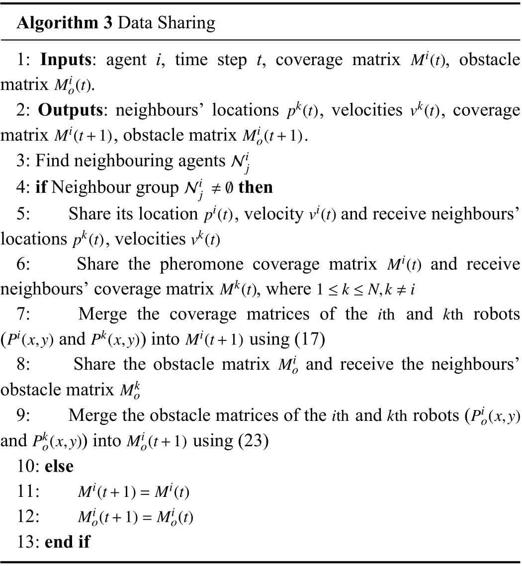
Algorithm 3 Data SharingMi(t)Mio(t)1: Inputs: agent i, time step t, coverage matrix , obstacle matrix.pk(t) vk(t)Mi(t+1) Mio(t+1)2: Outputs: neighbours’locations , velocities , coverage matrix , obstacle matrix.Nij3: Find neighbouring agents Nij≠∅4: if Neighbour group thenpi(t) vi(t)pk(t) vk(t)5: Share its location , velocity and receive neighbours’locations , velocitiesMi(t)Mk(t) 1 ≤k≤N,k≠i6: Share the pheromone coverage matrix and receive neighbours’coverage matrix , whereith kthPi(x,y) Pk(x,y) Mi(t+1)7: Merge the coverage matrices of the and robots( and ) into using (17)Mio8: Share the obstacle matrix and receive the neighbours’obstacle matrixith kth Pio(x,y)Pko(x,y) Mio(t+1)Mko9: Merge the obstacle matrices of the and robots (and ) into using (23)10: elseMi(t+1)=Mi(t)11:Mio(t+1)=Mio(t)12:13: end if
E.Complexity Analysis
In this section we examine the time and memory complexity of the algorithm components described above.
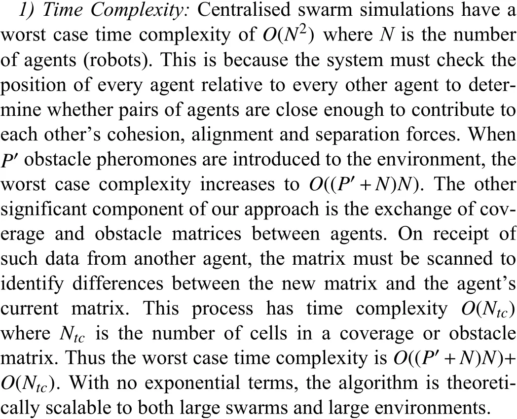
In our experiments in this paperO(Ntc) is the dominant term for the purpose of time complexity, as the number of cells is significantly larger than bothP′and the square of the number of robots.This is likely to be the case for many real-world applications (such as that simulated in Experiment 4), in particular, if the implementation of the swarming is distributed rather than centralised.
2) Memory Complexity:The algorithm presented in this paper requires each robot to maintain two fundamental data structures: the shared pheromone coverage matrix and the shared obstacle pheromone matrix.The memory requirements of these matrices are determined by the size of the environment and the grid cell resolution used.For example in a rectangular environment of sizeXbyY(metres) and a grid resolution ofRmetres, the memory requirement of each matrix isO(X/R∗Y/R).
IV.EXPERIMENTS
This section demonstrates the capabilities of our dynamic frontier-led swarming approach through a series of real-world experiments and simulations.These environments will be presented in Section IV-A.Our algorithm configurations are presented in Section IV-B.Our suite of performance metrics will be presented in Section IV-C.Results and Discussion are presented in Section IV-D.
A.Experimental Environments
Our real-world, real-time experiments are conducted on a small robotics range with real robots.This is discussed in Section IV-A-1).Simulations are conducted in a physics-enabled simulator mock-up of real urban terrain.This is discussed in Section IV-A-2).
1) Real-Robot, Real-Time Environments:The experiments were carried out on both homogeneous (seven TurtleBot Burgers) and heterogeneous (six TurtleBot Burgers and two Pioneer P3-DX) mobile robot platforms; see Fig.7.The robot operating system (ROS) framework provides a dynamic control interface for unmanned ground vehicles (UGVs).The software sends desired velocity commands (e.g., yaw rate Ω and linear velocityV) to the robots’embedded servo motor controller.
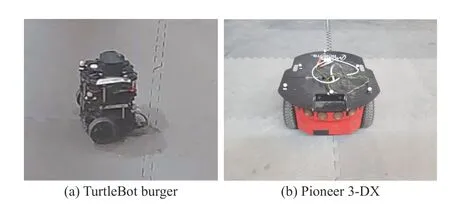
Fig.7.Two types of mobile robots were employed in our experiments.
For our experiments, we use a 4.3 m × 5.1 m test area.We conducted some experiments in an empty, walled arena (i.e.,no obstacles) and some experiments in settings with dynamic obstacles.The former setup permits us to test repeated coverage performance, while the latter setup permits us to test repeated coverage performance in the presence of unexpected,dynamic obstacles.
We used 6 obstacles: 3 small static obstacles (boxes) and 3 dynamic obstacles (Turtlebot Burger robots) as shown in Fig.8(a).For visualisation purposes, the obstacles are represented by red circles in theRVizgraphical user interface provided with ROS.The mobile obstacles’radii are 0.36 m, double that of a stationary obstacle.Agents are displayed as green circles in RViz.The frontier regions are displayed as green cells in RViz, the undiscovered cells as white, and the discovered cells as blue.The currently selected frontier cell is shown by a yellow circle as presented in Fig.8(b).The yellow circles’radius is scaled by the cost function calculated from (18).
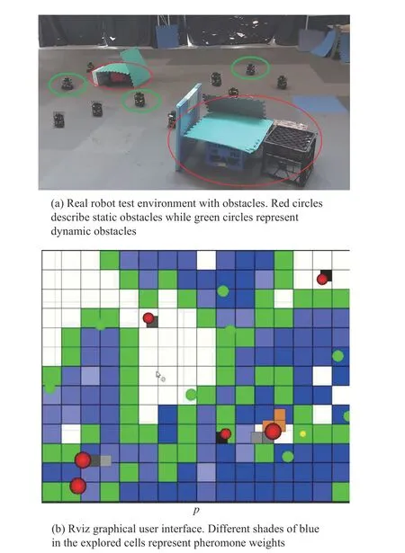
Fig.8.Turtlebot UGVs performing coverage in a real-time experiment.Real world (top) and graphical representation (bottom) are shown.
We used robots as the“dynamic obstacles”in this paper.The dynamic obstacles’linear velocity and heading are set randomly using a uniform distribution, ranging from[0.03,0.1]and [0,π/2], respectively.They were located at random positions with arbitrary headings.
Testing was conducted in an indoor laboratory fitted with a VICON motion capture system (MCS) to track the robot poses.The tracking data (e.g., position, velocity, and yaw angle) are streamed via the user datagram protocol (UDP) network protocol to each robot every 0.02 s.To improve the algorithms’robustness, all proposed approaches and the multi-ROS Master architecture were implemented on each robot without any central nodes.Furthermore, although the VICON system has complete knowledge of all robot state information,data is restricted so that robots can only access information about other robots if they are deemed sufficiently close.
2) Simulation Environments:Simulations allow us to study more complex environments than those available to us in the real-robot experiments in our limited-spaced MCS lab.The simulation studies are launched using a PC running Ubuntu,ROS Kinetic, and Gazebo’s Pioneer P-3DX and TurtleBot Burger3 models.The simulated environment is a replica of the Canberra campus of the University of New South Wales,shown in Fig.9.A larger robot team comprising 15 TurtleBot Burger3 and 5 Pioneer P-3DX mobile robots is used.Five mobile-robot obstacles are included, as well as static obstacles (buildings) in Gazebo.The obstacles’linear speed is randomly set in a high range of [0.1, 2.0] m/s.Using a cell sizeεof 1m, the considered arena is set to 50 m × 26 m, involving 542 free cells and 758 static obstacle cells.
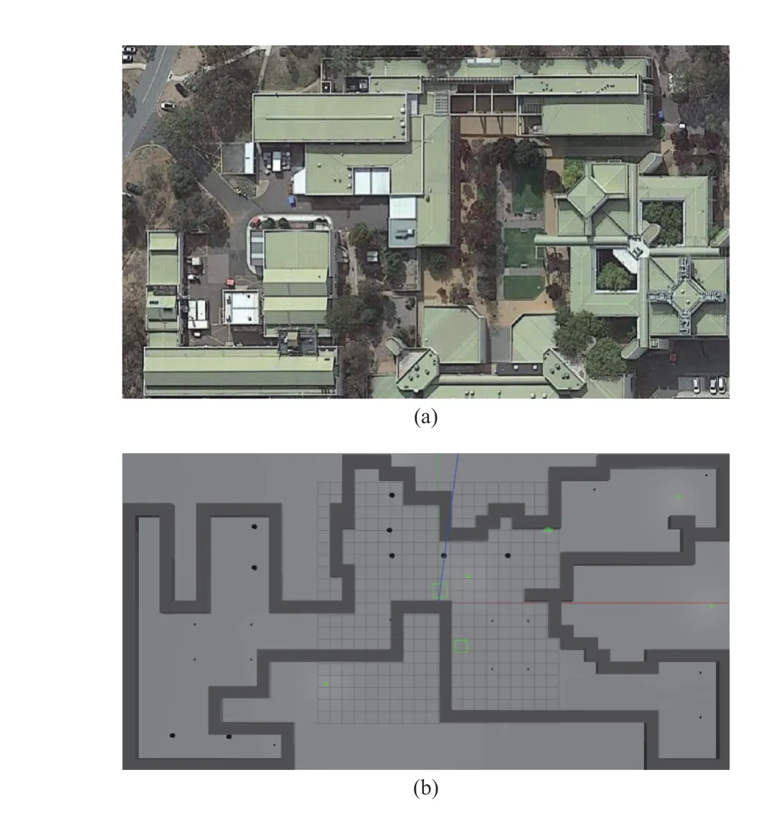
Fig.9.(a) Real environment (University of New South Wales at Canberra)(b) Virtual Gazebo environment.
B.Algorithm Configuration
Each robot’s maximum linear speed is 0.18 m/s, and the maximum angular velocity is set to ± 0.71 rad/s.Table II summarises all remaining parameter settings for the real-time experiments.These parameters were configured and tuned manually using specified rules of thumb for boid swarms [44]as follows.The cohesion force is established first to achieve grouping values in the desired range.The alignment radius is the same as the cohesion radius, but the alignment weight is approximately double the cohesion weight.The separation and obstacle avoidance forces are then set to be stronger again but operate in a smaller radius such that collisions do not occur,but grouping is maintained.The frontier weight is set to a small enough value such that it does not disrupt the formation but so that robots will pursue a frontier.The coverage pheromone evaporation rate was set based on the environment size so that there will always be some area requiring a repeated visit.The static obstacle pheromone evaporation rate was set slightly smaller than the coverage pheromone evaporation rate due to low demand for revisits.The mobile obstacle pheromone evaporation rate was configured based on a predicted maximum obstacle speed and the desired number of cells to be predicted in the trajectory of any obstacle (from 3 to 6 cells).Suppose the obstacle speed is faster than the evaporation rate of obstacle pheromones (less than or equal to 2 future obstacle cells predicted).In that case, this parameter needs to be re-tuned to avoid moving obstacles more safely and efficiently.
The coverage pheromone evaporation time isE= 750 s, while the static and dynamic obstacle evaporation time is 700 s and 8 s, respectively.The sample rate and the update frequency for swarming rules are 30 Hz.The communication rate for the coverage and obstacle matrices is 10 Hz.After a maximum coverage time of 1100 s, all mobile robots involved in the test are driven back to the“Home Base”point located at (0, 0)m.All internal coverage grids obtained at the time of 1100 s are synchronised when the inter-robot distance is sufficiently close.All remaining parameters are set to be the same as those implemented in the real robot experiments (see Table II).
C.Performance Metrics
Three criteria are chosen to evaluate the performance,namely criteria for coverage, criteria for formation control and criteria for obstacle avoidance.All the experiments are executed 5 times.Mean and 95% confidence intervals are reported where appropriate.The StandardP-Value from the Student T-test is used to distinguish the performance of different algorithms.If the variance of means between two sets is less than the expectedPvalue of 0.05 (i.e., 5%), we assume the results are statistically significant.
1) Coverage Metrics:The key metric used in this paper to measure coverage records the number of cells that the agents can keep filled with a non-zero pheromone.We call these metrics the coverage percentage (CP) (33) and the average coverage percentage (ACP) (34), but note that they are dependent on the evaporation time of the pheromones.The lower the evaporation time, the harder the robots need to work to maintain repeated coverage.In this paper we use a pheromone evaporation time of 100s in our real-time experiments, and 750 s in our simulated large environments.

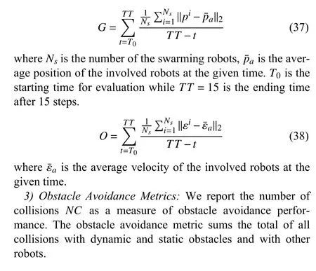
2) Swarm Metrics:We use two metrics for examining swarm behaviors: The first metric is the“group”metricG(37), which evaluates how closely grouped a set of robots is.The second metric is the“order”metric (38), which calculates the quality of the robots’alignment.
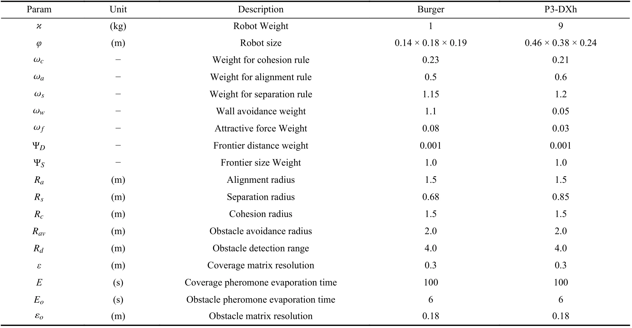
TABLE II PARAMETERS OF DYNAMIC FRONTIER-LED SWARMING AND THEIR EXPERIMENTAL VALUES
D.Results and Discussion
The first experiment examines our dynamic frontier-led swarming algorithm with a single evaporation time.It is compared to an existing approach from the literature.The second experiment evaluates the performance of our dynamic frontier-led swarming algorithm with multiple evaporation times prioritizing revisits to different areas of the environment.The third and fourth experiments are devoted to examining collision avoidance performance.We compare three alternative algorithms from the literature: APF [47] and enhancedD⋆[48].
1) Experiment 1 (Dynamic Frontier-Led Swarming With a Single Pheromone Evaporation Time):This experiment examines our dynamic frontier-led swarming algorithm (denoted FSP) with a single evaporation time.We examine the performance of two swarm types: a swarm of homogeneous robots and a swarm of heterogeneous robots.Performance is compared to an existing approach from the literature (denoted BSP).The results of this experiment are shown in Figs.10 and 11.We can see that allCPlines in Figs.10(a) and 11(a) oscillate around the steady-state values, indicating consistent,maintained repeated coverage (around 70−90%).The reason that coverage is reported as less than 100% is that the pheromone evaporation time is appropriately fast enough such that there is always some part of the environment that needs to be revisited.This stimulates continuing movement of the robots.
We see from Figs.10(b) and 11(b) that our FSP algorithm can maintain a higher coverage percent than the BSP algorithm.The FSP achieves 70.89±0.026%ACPfor the homogeneous robot swarm and 71.68±0.075%ACPfor the heterogeneous robot swarm, which are 3+0.05% and 10−0.008%higher than the BSP algorithm.Moreover, p-values for two robot swarms are 0.0006 and 0.0004, indicating the pairwise difference between the two coverage performances is significant.
Although theACPfigures are approximately 7 0%−75% after 300 s, the coverage percentages converge around78%−97%for the FSP and only 65%−82% for the BSP (see Figs.10(a)and 11(a)).The results mean that the FSP generates only 6−42 cells that need to be revisited every sample time while for BSP 37−73 cells need to be revisited with respect to the total 208 free cells.In the BSP , only the minimum distance from the frontier candidate to the robot position is used in the optimization function.This function is not optimal when a big swarm must visit only one cell.In contrast, the FSP’s optimization function as in (18) considers not only the minimum distance criteria but also the frontier size, which indirectly takes the swarm size into account.
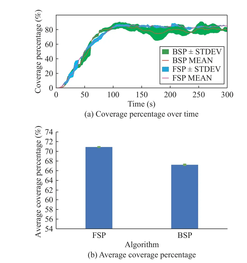
Fig.10.Experiment 1: Repeated area coverage results using homogeneous robots - number of cells with a non-zero pheromone present.
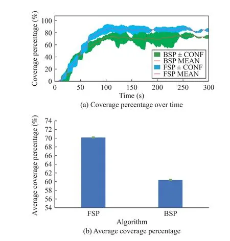
Fig.11.Experiment 1: Repeated area coverage results using heterogeneous robots - number of cells with a non-zero pheromone present.
Typical performance examples can be viewed in the online supplementary videos (FSP: https://youtu.be/U2AFCo8frD8 and BSP: https://youtu.be/U2AFCo8frD8).
Regarding the multi-robot formation performance, the swa
rm metricsGandOin Table III indicate tight formations are maintained by both algorithms.Both the FSP and BSP generate a distribution ofGin the range of [0.68,1.5]m and a slight alignment differenceOof merely 0.08±0.001 m/s.
2) Experiment 2 (Dynamic Frontier-Led Swarming With Multiple Evaporation Times):As mentioned in Section III-B,different pheromone evaporation times can be set to assign visitation priorities to different environmental regions.Thus,in the second experiment the environment was split into the three sections of interest (PA1,...,PA3), with different pheromone evaporation times in effect for each section (see Fig.12).The evaporation rate of the border area is seven times slower than the middle area, and the evaporation rate of the center area is seven times faster.This experiment compares dynamic frontier-led swarming with single and multiple evaporation times.We denote these FSP and FSPD, respectively.
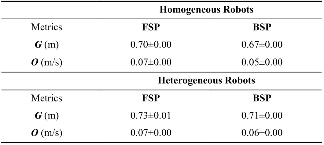
TABLE III EXPERIMENT 1: SWARM METRIC RESULTS
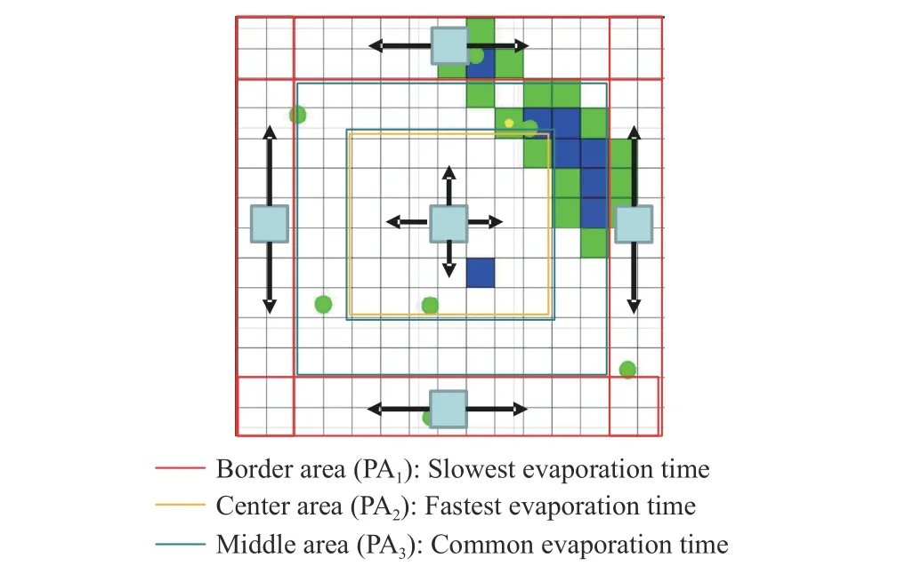
Fig.12.Experiment 2: pheromone evaporation times for regions with different re-visitation priorities.
The time spent in each area of the environment is shown in Fig.13.It is clear that the various pheromone evaporation rates alter the performance of the algorithm.The FSPD variant spends less time in the border area and middle area (by 11.06 s and 19.61 s) compared to the FSP due to lower pheromone evaporation speeds; whereas, time spent in the center area time increases by 30.71 s using FSPD due to the higher pheromone evaporation speed.P-values are less than our chosenαlevel of 0.05 indicating the difference in performance is statistically significant.Therefore, using our dynamic frontier-led swarming algorithm with multiple pheromone evaporation rates is a feasible solution to control monitoring frequency.
3) Experiment 3 (Obstacle Avoidance Performance of Dynamic Frontier-Led Swarming in Real-Time Environments):So far, we have examined FSP solving the repeated coverage problem without accounting for obstacles.Therefore, in this third experiment, we specifically examine the obstacle avoidance performance of our approach.We benchmark it against variants of dynamic frontier-led swarming using two alternative obstacle avoidance approaches, APF and D⋆Lite.We denote these FSP-APF and FSP-DL respectively.

Fig.13.Experiment 2: Time spent in each of the three priority areas by groups of robots using the FSP and FSPD strategies.
The evaluation metrics for this experiment are detailed in Table IV.All statistics reflect that FSP has considerably better performance than the FSP-DL and the FSP-APF as no collision is recorded in the five test runs.The latter methods are strongly affected by many collisions, achieving only 51.08±0.057% and 63.57±0.044%ACP, respectively,compared to 69.95±0.097%ACPachieved by FSP.The lack of a next obstacle position predictor, local minima traps,imbalance between the repulsive force and the attractive force,and drift motions when tracking are the main reasons causing the ineffective obstacle avoidance steering behaviors of FSPAPF and D⋆Lite.

TABLE IV EXPERIMENT 3: COVERAGE, FORMATION AND OBSTACLE AVOIDANCE PERFORMANCE FOR DYNAMIC FRONTIER-LED SWARMING IN REAL ENVIRONMENT
On the other hand, we can see that theGandOfigures of the FSP-APF, FSP-DL and FSP are higher than those recorded in Experiment 1 (see Table III).This is because encountering an obstacle has a small un-grouping effect on the swarm.While the difference is statistically significant (approximately 10%increase in grouping metric), the practical impact on swarming is minimal, such that robots still maintain a 0.8 metre average distance to each other.
Demonstration videos of all solutions compared in Experiment 3 can be viewed at the following address: FSP-APF:https://youtu.be/auRNFrbp6n0; FSP-DL: https://youtu.be/Cz-Tcv1_eGas; and FSP: https://youtu.be/nY6lnQ3UnUg.
Also available as supplementary videos (https://youtu.be/HIECd1bsGw8) are comparisons of our approach with a thirdorder polynomial curve fitting prediction algorithm, widely used in the reciprocal velocity obstacles (RVO) and hybrid reciprocal velocity obstacles (HRVO) strategies [49].Both strategies are examined in the same experimental scenario containing three dynamic obstacles: one moving with a figure of eight-shaped trajectory, one moving with a circular orbit,and one moving with linear motion.FSP has no collisions while the curve fitting approach has 7.50±0.7 collisions on average.
4) Experiment 4 (Obstacle Avoidance Performance of Dynamic Frontier-Led Swarming in Simulated Large-Scale Environments):As shown in the columns of Table V, FSP outperforms the other approaches in most evaluation metrics.During operation, the robots using the FSP method successfully avoid all obstacles (NC= 0) while many collisions are executed by FSP-APF and FSP-DL.Consequently, our approach generates 42.88±0.05 average coverage, which is almost twice theACPof the FSP-DL and four times higher than the FSP-APF.The FSP approach also provides the fastest average and maximum revisiting frequencies at only70.49±0.16 s and 1 94.33±0.82 s.FSP-DL demonstrates significantly higher time metrics and the FSP-APF generates the largest AT and LT, standing at 1 10.52±0.33 s and 3 42.68±1.2 s respectively.
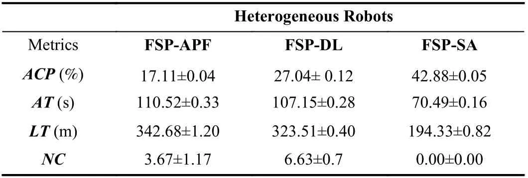
TABLE V EXPERIMENT 4: EXPERIMENTAL SWARM EVALUATION OF OBSTACLE AVOIDANCE SOLUTIONS FOR REPEATED COVERAGE PROBLEM IN A LARGE, SIMULATED ENVIRONMENT
Moreover, these positive results consolidate our arguments in Experiment 4.As shown in Fig.14(a), the FSP-APF multiagent path planning method possesses a local minimum problem, which can trap mobile robots before reaching their goal[36].The D⋆Lite algorithm is free from pitfalls such as converging to local minima.However, its actual performance is dependent upon the size of the grid.Furthermore, in case of a change in the obstacle-map, a long delay can occur when the robot path needs to be re-planned [50], resulting in several potential collisions with high-speed dynamic obstacles(Fig.14(b)).Finally, our distributed obstacle avoidance system predicts the future obstacle motions using pheromone evaporation, computes the closest safe angle, and then adjusts the robot’s orientation.Hence, the frontier-driven swarming algorithm with obstacle avoidance reduces the computational complexity and escapes from local minima traps and oscillatory movements.It thus appears better suited for various undiscovered and cluttered urban environments (see Fig.14(c)).
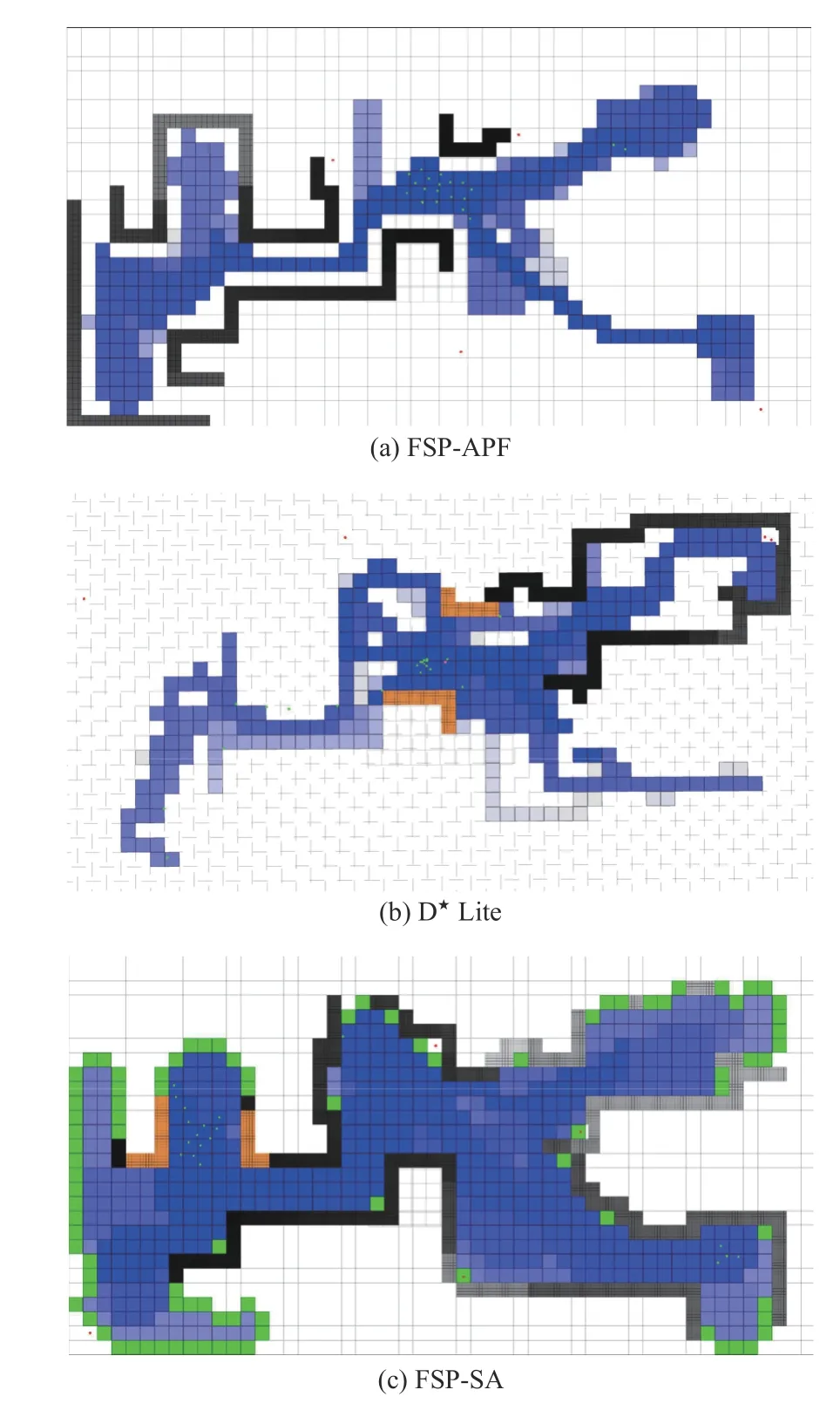
Fig.14.Experiment 4: Example coverage results for university landscape after 1100 s.
V.CONCLUSION AND FUTURE WORK
This paper has presented an algorithm for repeated coverage by multi-robot patrols in environments with unknown static and dynamic obstacles.Our key conclusions are:
1) Our dynamic frontier-led swarming algorithm can achieve repeated area coverage while maintaining a tight, selforganising robot formation.These results were demonstrated in small and larger-scale environments, with different homogeneous and heterogeneous robot swarms.
2) Re-tuning of algorithm parameters is not required to transfer the system to different robot swarms.However, it may be required if the speed of dynamic obstacles is very high.
3) Regions in a map can be revisited with different frequencies, by using different pheromone evaporation rates.
4) Our pheromones-based obstacle avoidance interacts favourably with the swarming and frontier components of our algorithm, achieving fewer collisions than other available obstacle avoidance strategies.
The possibilities for future work in this area are rich.The advantage of the swarm approach is its robustness to the failure of individual agents and its ability to function without global control due to local communications between individuals.In future work, we will examine the capacity of our algorithms to continue to solve coverage problems in the presence of a range of intermittent problems.These may include delayed or loss of communication, loss of positioning and failure of individual units.Other directions for future work include relaxing the assumptions that the boundaries of the environment are known and that the robots’grid discretizations and localization on the map are known.
This paper has focused on a single manually tuned swarming configuration.However, there is scope to improve performance by autonomously optimising the swarming parameters,for example by using an evolutionary approach.There is also a potential for performance improvement by permitting adaptation of the swarm formation on the fly, for example, looser formations in open areas and tighter formations in narrow spaces.These form key avenues for future work.
杂志排行
IEEE/CAA Journal of Automatica Sinica的其它文章
- Meta-Energy: When Integrated Energy Internet Meets Metaverse
- Cooperative Target Tracking of Multiple Autonomous Surface Vehicles Under Switching Interaction Topologies
- Distributed Momentum-Based Frank-Wolfe Algorithm for Stochastic Optimization
- A Survey on the Control Lyapunov Function and Control Barrier Function for Nonlinear-Affine Control Systems
- Squeezing More Past Knowledge for Online Class-Incremental Continual Learning
- Group Hybrid Coordination Control of Multi-Agent Systems With Time-Delays and Additive Noises
