片状碳载金属纳米颗粒复合物的制备及其氧还原电活性
2023-02-27章巧丽王雅萍孙万杰易清风
章巧丽 王雅萍 孙万杰 易清风*,,2
(1湖南科技大学化学化工学院,湘潭 411201)
(2新能源储存与转换先进材料湖南省重点实验室,湘潭 411201)
0 Introduction
As a non‑renewable energy source,fossil fuels have been gradually depleted through continuous min‑ing and utilization by human beings,and the use of fos‑sil fuels has also brought many environmental prob‑lems.These problems are always affecting the progress and development of our society,making the develop‑ment of green and clean technology necessary[1‑2].Oxygen reduction reaction(ORR)is a cathode reaction of fuel cells.The high binding energy of O2molecules leads to high overpotential and poor performance for the catalysts of ORR,which limits the energy conver‑sion efficiency and greatly hinders the large‑scale com‑mercial application of fuel cells[3‑5].Platinum and platinum‑based materials are considered to be the best catalysts discovered so far due to their low overpoten‑tial and kinetic improvement.However,platinum also has some disadvantages such as high price,scarcity,and poor stability[6‑8].Therefore,the research and devel‑opment of novel ORR catalysts with low prices,easy ac‑quisition,and good stability have always been the focus of the research[9].
Although carbon‑based materials themselves do not have excellent ORR catalytic properties,they can act as excellent catalyst carriers because of their good electrical conductivity,mechanical stability,chemical stability,abundant resources,and low price[10].The modified carbon‑based materials show efficient ORR activity in the cathode reaction of fuel cells and become the most promising catalyst materials.Metal nanoparticles can increase the active sites on the sur‑face of carbon‑based materials and promote the graphi‑tization degree of carbon‑based materials;Heteroatoms(such as N,P,B,S,etc.)doping can change the charge distribution and spin of the carbon conducting network and promote the adsorption of oxygen,thus improving the electrical conductivity and catalytic performance of the material[11‑14].It was found that metal‑loaded lamel‑lar N‑doped carbon nanocomposites could combine the advantages of metal nanoparticles and heteroatoms to improve the electroactivity and stability of the catalysts.Among them,the transition metal‑nitrogen‑carbon(M‑N‑C)moiety has abundant M‑NXactive sites on carbon‑based materials and has good electrocatalytic activity,stability,and tolerance in acidic and alkaline media[15‑18].The highly electronegative nitrogen atoms can effectively regulate the electron distribution and charge density of the adjacent carbon atoms.Transition metal cobalt and iron are rich in resources and easy to be prepared.The combination of their nanoparticle and carbon‑based materials can greatly improve the electro‑activity of the formed catalysts,so they are widely used in the design and preparation of ORR catalysts[3‑4].
Considering that the current preparation process of the M‑N‑C catalysts is complicated and their ORR electroactivity in acidic media is generally weak,we synthesized the nitrogen‑doped carbon nanosheet sup‑ported metal nanoparticles(Co/C‑N,Fe/C‑N,and Fe‑Co/C‑N)by using an all‑solid‑state method through a simple high‑temperature pyrolysis;Subsequently,based on the electroactivity test of ORR,a small amount of platinum was further deposited on the Co/C‑N with good ORR electroactivity by thermal reduction method to obtain Co‑Pt/C‑N.The samples were charac‑terized in detail and their ORR electrocatalytic proper‑ties were tested in full pH ranges(acidic,neutral,and alkaline).
1 Experimental
1.1 Materials
Dicyandiamide and Nafion solution(5%,Dupont)were purchased from Sinopharm Chemical Reagent Co.,Ltd.Sucrose was purchased from Tianjin Kemiou Chemical Reagent Co.,Ltd.Cobalt phthalocyanine,iron phthalocyanine,and acetylacetone platinum were purchased from Aladdin Chemical Reagent Co.,Ltd.Pt/C(40%,Johnson Matthey Corp.)was purchased from Shanghai Qunyi Energy Equipment Co.,Ltd.Anhy‑drous ethanol was purchased from Hunan Huihong Reagent Co.,Ltd.Ultrapure water was made by ultra‑pure water generator.
1.2 Preparation of Co/C⁃N,Fe/C⁃N,and Fe⁃Co/C⁃N
3 g dicyandiamide,0.4 g sucrose,and 0.1 g cobalt phthalocyanine(or 0.1 g iron phthalocyanine,or 0.05 g cobalt phthalocyanine+0.05 g iron phthalocyanine mixture)were mixed in a mortar.Next,the mixture was ground thoroughly with a small amount of ethanol in the mortar.The mixture was transferred to a beaker and dried in a vacuum oven at 60℃.Then it was ground again to form a powder,placed in a crucible,and transferred to a tubular furnace to be subjected to the pyrolysis treatment.Before heating,pure N2gas was passed through the furnace for 15 min to drain O2from the tubular furnace.In the N2atmosphere,it was heated to 550 ℃ at a heating rate of 4 ℃·min−1for 2 h and then heated to 800℃at the same heating rate for another 2 h.After cooling to room temperature,the black powder was collected and transferred to a mortar for grinding to obtain the sample Co/C‑N.Other two samples Fe/C‑N and Fe‑Co/C‑N were also prepared using the same steps as the Co/C‑N when 0.1 g cobalt phthalocyanine was replaced with 0.1 g iron phthalocy‑anine,or 0.05 g cobalt phthalocyanine+0.05 g iron phthalocyanine mixture,respectively.
1.3 Preparation of Co⁃Pt/C⁃N
50 mg Co/C‑N and 10 mg acetylacetone platinum were mixed and fully ground with a small amount of ethanol.The mixture was then dried in a vacuum oven at 60℃.The solid obtained was transferred to a tubu‑lar furnace and heated to 260 ℃ at a rate of 4 ℃·min−1in an N2atmosphere for 2 h.Co‑Pt/C‑N was obtained after cooling to room temperature.The preparation pro‑cess is shown in Fig.1.

Fig.1 Schematic diagram for preparation of the catalyst Co‑Pt/C‑N
1.4 Characterization and testing
The morphology and structure of the catalysts were characterized by scanning electron microscopy(SEM,FEI Inspect F50 SEM,10 kV)and transmission electron microscopy(TEM,JEOL JEM‑2100,200 kV).The types and contents of elements in the samples were analyzed by energy dispersive spectroscopy(EDS,super‑octane).The elemental composition and bonding state of the catalysts were analyzed by X‑ray diffraction(XRD,Cu Kα radiation,λ=0.154 18 nm,40 kV,250 mA,2θ=10°‑85°)and X‑ray photoelectron spectrosco‑py(XPS,Thermo Fisher,ESCALAB Xi+).
The ORR performances of the catalysts were test‑ed on AutoLab PGSTAT30/FRA electrochemical work‑station in a three‑electrode system using a rotating disk electrode(RDE).The working electrode was glassy car‑bon(GC,0.071 cm2)electrode coated with a catalyst.The auxiliary and reference electrodes were Pt wire and Ag/AgCl(sat.KCl)electrodes respectively.All potentials in this work were against the Ag/AgCl elec‑trode.The working electrode was fabricated by coating 20µL the ink dispersion of the sample catalyst on the GC surface.The ink was prepared by ultrasonically mixing a 3 mg sample,30µL Nafion solution,and 570µL anhydrous ethanol to form a uniform ink dispersion.As a comparison,the Pt/C working electrode was also prepared by coating 10µL Pt/C ink on GC.The cyclic voltammetry(CV)and linear sweep voltammetry(LSV)curves of the catalysts in acidic(0.1 mol·L−1HClO4),alkaline(0.1 mol·L−1KOH),and neutral(4 mol·L−1NH4Cl+1 mol·L−1KCl)solution were tested under satu‑rated O2and N2.
According to the Koutecky‑Levich Formula 1[19],the number of ORR transferred electrons(n)was calcu‑lated:
where j,jk,and jdrespectively refer to the measured cur‑rent density,dynamic current density,and limit diffu‑sion current density;B is the slope of the Levich curve;ω is the rotating speed;and n value is reckoned accord‑ing to Formula 2:

where n was the number of transferred electrons,F refers to the Faraday constant(96 500 C·mol−1);cO2is the concentration of saturated O2in the electrolyte solu‑tion at room temperature(1.2×10⁻⁶mol·cm−3);DO2is the diffusion coefficient of O2in water(1.93×10⁻⁵cm2·s−1);v is the kinematic viscosity of the solution at room temperature(0.01 cm2·s−1)[20].
2 Results and discussion
2.1 Morphology of catalyst
The morphology of the catalysts was observed by SEM images.As shown in Fig.2a‑2d,all samples pre‑sented morphology characteristics of a large number of micron‑sized sheet‑like carbon structures,which were stacked together to form a thickness of tens of nanome‑ters.During pyrolysis,carbon nanosheets with rich folds and distinct stratified structured were formed from dicyandiamide,exposing more active sites at the edge and thus further improving the performance of the sample[9,14].No obvious metal nanoparticles could be seen in the SEM images,which may be attributed to the fact that the metal nanoparticles are tightly wrapped by the graphitic carbon shell formed and they also present small sizes[21].

Fig.2 SEM images of Co/C‑N(a),Fe/C‑N(b),Fe‑Co/C‑N(c),and Co‑Pt/C‑N(d);TEM images of Co/C‑N(e‑h);EDS mappings of C,N,O,Co,and Pt of Co‑Pt/C‑N(i‑m)
The 3D fine structure inside Co/C‑N was further observed by TEM.TEM images(Fig.2e)show that Co/C‑N revealed a sheet‑like morphology similar to multi‑layer graphene with many folds.In Fig.2f‑2h,Co nanoparticles were evenly distributed on graphite car‑bon nanosheets without obvious agglomeration[21‑22].Fur‑thermore,Fig.2g demonstrates that graphene layers were formed during pyrolysis with a lattice spacing of 0.355 nm,consistent with crystal planes of graphite(002)[23].As shown in Fig.2g,particles with a lattice spacing of 0.199 nm correspond to the face‑centered cubic crystal plane of Co(111)[21],while the lattice dis‑tance of 0.228 nm might correspond to the crystal plane of Co or Co3C(200).The increase of lattice spac‑ing of Co nanoparticles might be caused by the combi‑nation of C and N with Co.It could be seen from Fig.2h that the graphene layer formed has a 23‑layer structure with a rich carbon layer and abundant active sites.Also,the sizes of Co nanoparticles fall into the range of ca.2‑2.4 nm with high uniformity.Fig.2i‑2m was the mapping image of C,N,O,Co,and Pt elements in cata‑lyst Co‑Pt/C‑N.All elements were evenly dispersed on the catalyst,proving that Co and Pt were successfully loaded on N‑doped carbon nanosheets.
2.2 Composition analysis of catalysts
XRD and EDS were used to analyze the types and contents of elements in the catalysts.According to the XRD patterns of the catalysts shown in Fig.3a,all the catalysts Co/C‑N,Fe/C‑N,Fe‑Co/C‑N,and Co‑Pt/C‑N displayed a well‑defined diffraction peak at 2θ=26.6°,which is attributed to graphite C(002).The catalyst Co/C‑N did not show an obvious Co diffraction peak,because the Co nanoparticles were tightly encapsulated by the graphite carbon shell and low metal content is present in the sample.According to the standard colori‑metric card of Fe(PDF No.06‑0696),the weak diffrac‑tion peak of Fe/C‑N at 2θ=44.37°corresponds to the standard peak of Fe at 2θ=44.67°,which could be attributed to the face‑centered cubic crystal plane of Fe(110)[6].According to the standard cards of Fe(PDF No.06‑0696)and Co(PDF No.15‑0806),a weak peak of Fe‑Co/C‑N at 2θ=44.48°was between the standard peaks of Co(2θ=44.22°)and Fe(2θ=44.67°).The result indicates that Fe‑Co alloy was formed during pyrolysis and could be attributed to crystal planes of Fe or Co face‑centered cubic structure(111)[3].For Co‑Pt/C‑N,the diffraction peak at 2θ=39.42°corresponds to the standard peak of Pt at 2θ=39.76°according to the standard card of Pt(PDF No.04‑0802),which could be attributed to Pt(111)plane.Fig.3b,3c shows the ele‑mental composition and mass percentage of all cata‑lysts,showing the characteristic peaks of C,N,O,Co,Fe,and Pt.The peaks at 0.78 and 6.92 keV are charac‑teristic peaks of Co,and the peaks at 0.71 and 6.40 keV are characteristic peaks of Fe.The peak at 2.06 keV is the unique peak of Pt.Results indicate that vari‑ous metal elements were successfully loaded onto the carbon nanosheets.
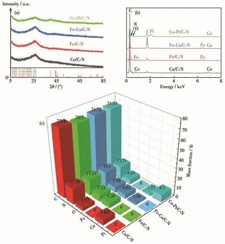
Fig.3 XRD patterns of all catalysts(a);EDS spectra of all elements(b);Element content of all catalysts by EDS(c)
The catalyst Co/C‑N was further analyzed by XPS to understand its chemical composition and structure.As shown in Fig.4a,the XPS spectra of the Co/C‑N cat‑alyst show elemental energy peaks corresponding to C(78.16%),N(20.82%),and Co(1.02%).The XPS spec‑tra of C1s(Fig.4b)were deconvoluted into four peaks at 284.7,285.9,287.3,and 288.9 eV corresponding to the characteristic peaks of C=C,C—O/C=N,O—C=O/C—N,and O—C=O respectively,confirming the successful combination of carbon and nitrogen.As can be seen from Fig.4c,there is the main peak of N1s at 398.3 eV,which is attributed to pyridine nitrogen.Peaks at 400.7 and 401.7 eV correspond to pyrrole nitrogen and graphite nitrogen respectively.Pyridine and graphite nitrogen could enhance ORR activity because the C atom near pyridine nitrogen and graph‑ite nitrogen could be the active site of ORR.The con‑tent of pyridine nitrogen determines the onset potential of ORR,and the content of graphite nitrogen plays a key role in the limiting current density of ORR[24‑26].The nitrogen contents of pyridine,pyrrole,and graphite were 57.84%,22.35%,and 19.81%,respectively.The high content of pyridine nitrogen for Co/C‑N indicates that the catalyst might have a high onset potential and outstanding electrocatalytic performance for ORR.Fig.4d shows that Co2p can be deconvoluted into three peaks at 778.2,779.8,and 781.3 eV,corresponding to Co,Co2+,and Co3+respectively.
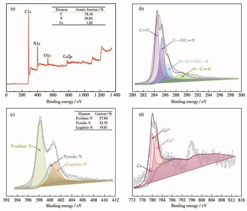
Fig.4 XPS full survey of Co/C‑N(a)and corresponding high‑resolution XPS spectra of C1s(b),N1s(c),and Co2p(d)
2.3 Electrochemical testing of catalyst
CV curves of all catalysts were measured in O2and N2saturated alkaline,acidic,and neutral solu‑tions.In an alkaline solution,the CV curves of the sam‑ples are shown in Fig.5a.Compared with the curves in the N2‑saturated solution,all the catalysts in saturated O2showed obvious cathodic peaks,and the current den‑sity increases significantly.As shown in Fig.5a,the cathodic peak potentials of Co/C‑N,Fe/C‑N,Fe‑Co/C‑N,Co‑Pt/C‑N,and Pt/C were located at−0.124,−0.180,−0.168,−0.112,and −0.182 V respectively,indicating that the samples present better electrocata‑lytic activity for ORR than Pt/C.In an acidic solution(Fig.5b),the CV curves of Co/C‑N,Co‑Pt/C‑N,and Pt/C catalysts showed obvious oxygen reduction peaks.The peak potentials of Co/C‑N,Co‑Pt/C‑N,and Pt/C catalysts were 0.252,0.608,and 0.642 V respectively,showing the significant improvement of the Co‑Pt/C‑N catalyst on ORR activity.However,Fe/C‑N and Fe‑Co/C‑N showed weak electrocatalytic performances for ORR in an acidic medium.In a neutral solution(Fig.5c),the CV curves of all catalysts showed weak cathodic peaks under O2saturation,although the cur‑rent density was higher than that under a nitrogen atmosphere.The cathodic peak potentials of the Co/C‑N,Fe/C‑N,Fe‑Co/C‑N,Co‑Pt/C‑N,and Pt/C were 0.150,0.235,0.194,0.152,and 0.230 V respectively,showing their efficient ORR activity in neutral medium.
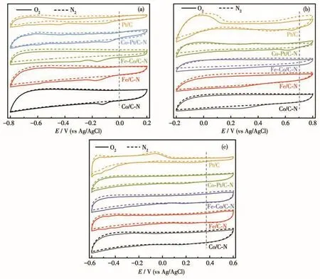
Fig.5 CV curves of all catalysts in alkaline(a),acidic(b),and neutral(c)solutions saturated with O2and N2at a scanning rate of 50 mV·s−1
The ORR performances of the catalysts were fur‑ther evaluated on a RDE.Fig.6a‑6c show LSV and Koutecky‑Levich curves of different catalysts in alka‑line,acidic,and neutral solutions at 1 600 r·min−1,respectively.The ORR onset potential,half‑wave potential,and limiting diffusion current density(jd)of the prepared catalysts and Pt/C are listed in Table 1.As the potential shifted to the negative direction,all catalysts exhibited a rapid increase of current density after the onset potential,followed by a well‑defined cur‑rent plateau.And Co/C‑N reveals more positive onset and half‑wave potentials and higher limiting diffusion current density than Fe/C‑N and Fe‑Co/C‑N.This may be related to the abundant pyridine nitrogen of Co/C‑N obtained from XPS analysis.On this basis,a small amount of platinum was loaded on Co/C‑N to form the Co‑Pt/C‑N.According to Koutecky‑Levich formula[19]and the illustration in Fig.6a‑6c,the number of trans‑ferred electrons for ORR could be calculated.As shown in Fig.6d‑6f,the numbers of transferred elec‑trons of all catalysts were between 3.7 and 4,showing a dominant four‑electron transfer process of ORR on the prepared samples in full pH ranges(alkaline,acidic,and neutral)[27].The corresponding catalytic mechanism for ORR on the prepared catalysts is depicted in Fig.1.Compared with the two‑electron transfer process,the four‑electron transfer process can output a higher ener‑gy density for fuel cells and metal‑air batteries[7,20,28].Further,Fig.6b and Table 1 show that the onset poten‑tial and half‑wave potential values of the Co‑Pt/C‑N were greatly improved in an acidic medium,which is comparable to that of the Pt/C.The stability of the cata‑lysts in a full pH range was also investigated by using successively sweeping cycle voltammetry.Fig.7 shows the 500 consecutive scanning CV profiles of the Co/C‑N and Co‑Pt/C‑N catalysts in alkaline(Fig.7a),acidic(Fig.7b),and neutral(Fig.7c)media.It is seen from Fig.7 that whether in acidic,alkaline,or neutral media,no significant change in the CV profile for the two cata‑lysts was observed after 500 times repeated cycles.A slight change in current density would be caused by a small change in oxygen gas concentration after consec‑utive scans.Results reveal excellent stability of the prepared catalyst in different pH electrolytes.It is gen‑erally considered that the ORR performance of the cat‑alyst in an acidic medium is critical for its potential application to proton exchange membrane fuel cells(PEMFCs)[29‑30].Unfortunately,the PEMFCs with non ‑precious metal cathodic catalysts generally exhibit poor performance due to their commonly lower ORR electroactivity in the acidic medium[31‑32].The prepared catalyst Co‑Pt/C‑N with low Pt loading reveals a prom‑ising application to PEMFCs.

Fig.6 LSV curves and Koutecky‑Levich curves in alkaline(a),acidic(b),and neutral(c)solutions obtained for all catalysts at saturated O2at a scanning rate of 5 mV·s−1and 1 600 r·min−1;Number of transferred electrons in alkaline(d),acidic(e),and neutral(f)solutions of all catalysts at O2saturation
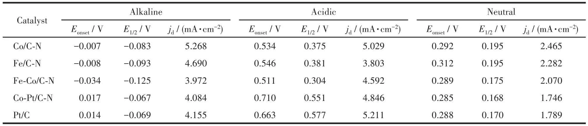
Table 1 Onset potential,half⁃wave potential,and limiting diffusion current density of the catalysts at 1 600 r·min-1under alkaline,acidic,and neutral conditions
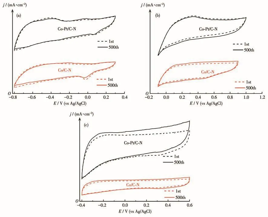
Fig.7 CV curves of Co/C‑N and Co‑Pt/C‑N in O2‑saturated alkaline(a),acidic(b),and neutral(c)solutions at 50 mV·s−1for the first and 500th cycles
3 Conclusions
In summary,we proposed an all‑solid‑state synthe‑sis method of highly efficient ORR electrocatalysts.Carbon nanosheets supported Co/Fe nanoparticles(Co/C‑N,Fe/C‑N,and Fe‑Co/C‑N)were first synthesized by a simple pyrolysis method.Then,a cobalt‑platinum cat‑alyst Co‑Pt/C‑N with low Pt loading was further synthe‑sized by thermal reduction based on Co/C‑N.The mor‑phological structure of Co/C‑N presents abundant car‑bon nanosheet folds,obvious stratification,and uniform dispersion of metal nanoparticles.And it contains high pyridine nitrogen and lots of active groups such as Co‑N.These lead to the excellent ORR electrocatalytic activity of the catalyst.The catalyst Co/C‑N in alkaline and neutral solutions showed superior ORR electrocata‑lytic activity to Pt/C.And the onset potential,half‑wave potential,and limiting diffusion current density of the Co‑Pt/C‑N catalysts were significantly improved,and its ORR electrocatalytic activity was close to Pt/C in an acidic medium.
Acknowledgments:Authors thank the financial support from the National Natural Science Foundation of China(Grant No.21875062)and the Innovation Training Program for College Students in Hunan Province(Grant No.S202210534022).
