宽增益高效率LLC谐振变换器拓扑
2023-02-22龚春阳朱国忠王志新
夏 潇,龚春阳,包 俊,朱国忠,王志新
宽增益高效率LLC谐振变换器拓扑
夏 潇1,龚春阳2,包 俊3,朱国忠4,王志新1
(1.上海交通大学电子信息与电气工程学院,上海 200240;2.上海电力大学,上海 200090;3.上海禧龙科技股份有限公司,上海 201517;4.上海正泰电源系统有限公司,上海 200210)
针对LLC谐振变换器增益负载敏感性强、与效率存在强耦合的不足,提出了一种由LLC 谐振变换器和两开关buck-boost构成的宽增益高效率LLC谐振变换器拓扑。通过采用输入并联与输出串联的方式,分别由LLC谐振变换器传输功率、buck-boost调节输出电压。其中,LLC谐振变换器运行于谐振频率,buck-boost采用PWM调节输出电压。分析了变换器的运行模式,给出了相应的参数设计方法,并进行了仿真验证。最后,对输入30 V、输出200~360 V、360 W样机进行了实验,实验样机增益范围和效率分别为6.67~12、97.4%。仿真与样机实验验证了所提出的宽增益高效率LLC变换器拓扑及其调制方法的有效性。
宽增益;高效率;LLC谐振变换器;谐振频率;两开关buck-boost
0 引言
LLC谐振变换器因具有自然软开关和高功率密度等特点受到了学术及业界关注[1-9],并广泛应用于直流电网、光充储用智慧建筑直流系统和储能系统等。通常LLC谐振变换器的运行频率低于谐振频率,一旦该运行频率远小于谐振频率时,变换器环流和开关管应力明显增大,尤其在重载时增益峰值减小,降低了变换器的电压调节能力[10],难以在宽频率范围保持高效率[11-12]。LLC谐振变换器运行在谐振频率时效率最高,但是,若将其运行频率固定为谐振频率,LLC谐振变换器无法满足输出电压调节要求。
为了提高变换器的增益范围和效率,文献[13-15]在LLC谐振变换器的基础上通过改变一次侧和二次侧的结构以拓宽增益,但同时使变换器的结构复杂化,可靠性降低。文献[16]提出一种LC耦合拓扑替换LLC谐振网络,获得了从零可调的宽增益,在轻载时增益特性良好,但重载时变换器峰值增益明显降低。文献[17]提出了两变压器拓扑,通过自适应改变励磁电感和等效匝数比来拓宽增益,但其控制难度较大。文献[18]采用两个LLC谐振网络来拓宽增益,但其特性本质上与LLC谐振变换器相同。文献[19]在LLC谐振网络中使用辅助开关加大谐振电感的储能以提高增益,增益受开关频率和元件参数的影响较大。文献[20]采用APWM调制LLC拓扑以拓宽增益,但该调制方法使变换器增益特性不单调,加大了控制难度。文献[21]基于LLC拓扑,通过改善调制策略以拓宽增益,但是调制方法较为复杂。文献[22]提出了一种五元件谐振变换器,相较于LLC谐振变换器,其谐振频率以上增益特性优良,但谐振频率以下增益特性和LLC谐振变换器相似,且谐振元件参数设计难度大。文献[23]在LLC 谐振变换器的谐振回路中串联变压器,其二次侧整流后与buck变换器级联,输出为并联连接,变换器在保持高效率的同时获得了一定的电压调节能力,但是结构较复杂。
对此,本文提出了一种由LLC 谐振变换器和两开关buck-boost构成的宽增益高效率LLC谐振变换器拓扑,通过采用输入并联与输出串联的方式,分别由LLC谐振变换器传输功率、buck-boost调节输出电压。其中,LLC谐振变换器运行于谐振频率、buck-boost采用PWM调节输出电压。
1 变换器拓扑与运行模式
1.1 变换器拓扑
变换器拓扑如图1所示。LLC 谐振变换器与两开关buck-boost采用输入并联、输出串联方式。其中,LLC 谐振变换器的运行频率固定在谐振频率,两开关buck-boost采用PWM调节输出电压。
变换器增益为


图1 变换器拓扑
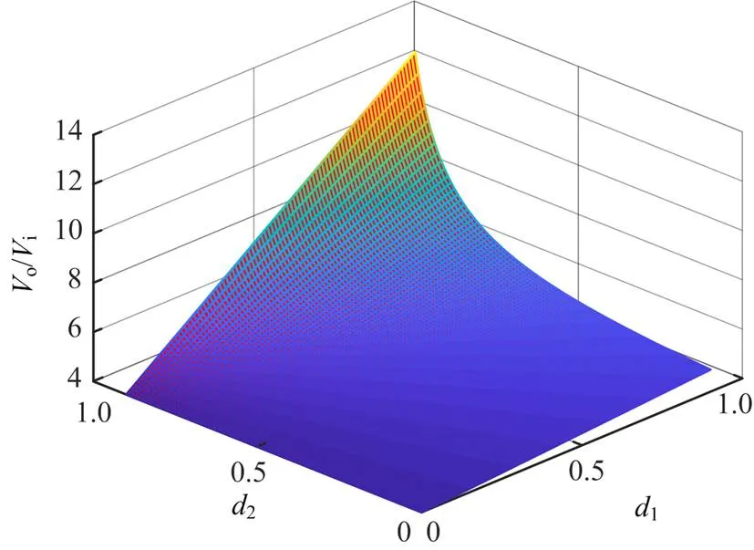
图2 变换器增益特性
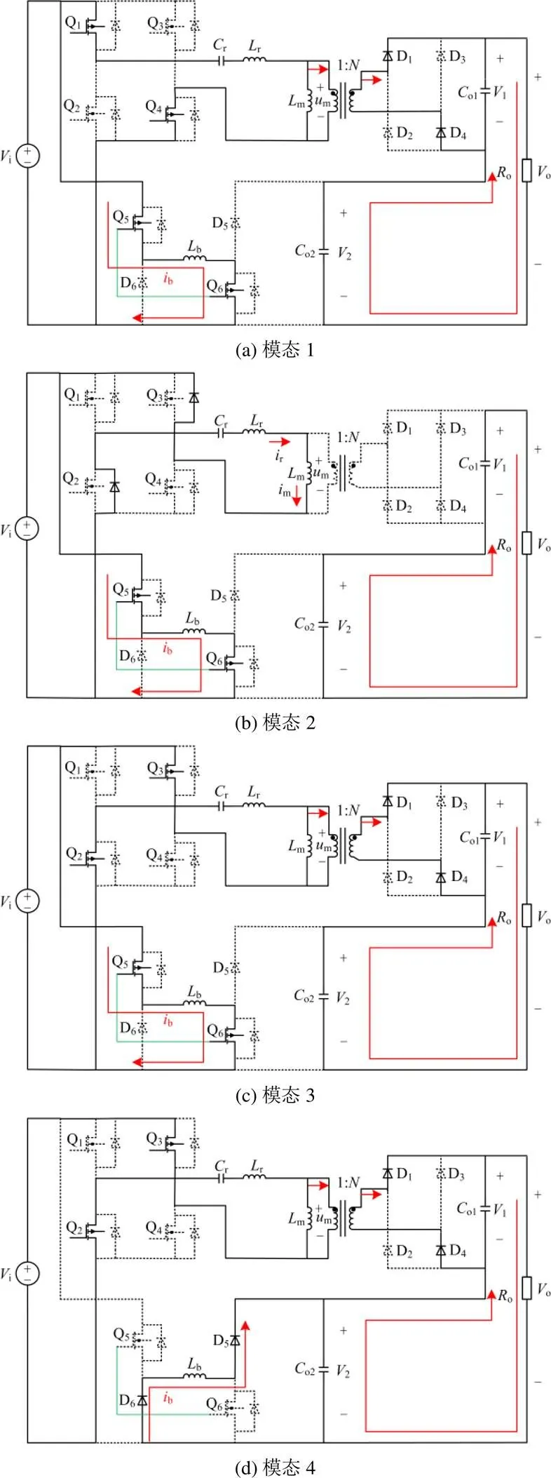
1.2 变换器运行模式
1.2.1连续模式


1.2.2断续模式

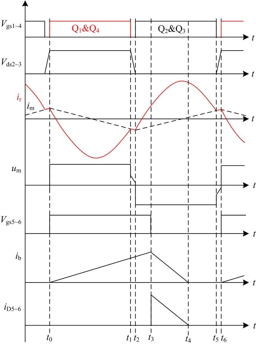
图5 电流断续时波形
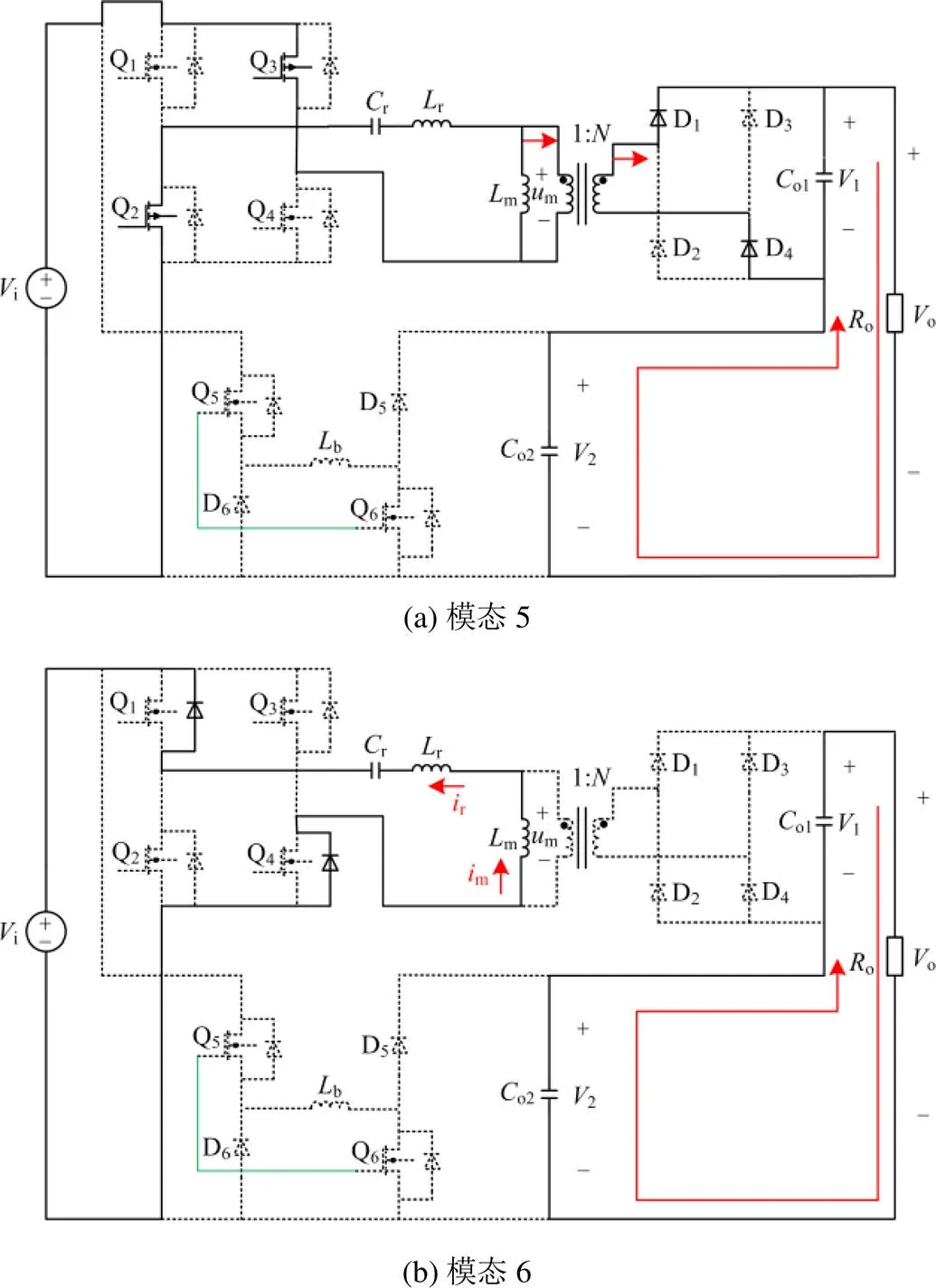
图6 电流断续模式模态
2 变换器增益分析
2.1 连续模式


由式(5)、式(6)得到变换器增益为

连续模式变换器增益特性如图7所示。
图7 连续模式变换器增益特性
Fig. 7 Converter gain characteristics of continuous current operation
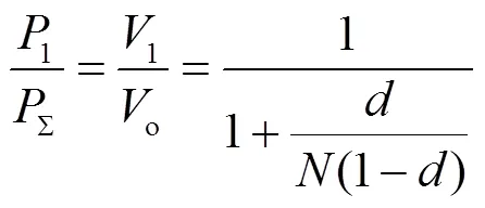
连续模式功率占比如图8所示,占空比与LLC 谐振变换器输出功率与变换器总输出功率的比值有关。其中,在0~0.8范围取值时,LLC 谐振变换器输出功率与变换器总输出功率的比值变化很小,取10时,功率比值下降20%左右。
2.2 断续模式
buck-boost的输出电压为

由式(5)、式(9)得到变换器增益为

图9为断续模式变换器的增益特性,增益随着占空比d的增加线性增大。
LLC 谐振变换器输出功率与变换器总输出功率的比值为
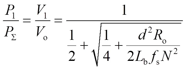
断续模式功率占比如图10所示。占空比对LLC 谐振变换器输出功率与变换器总输出功率的比值影响很大,在0~0.8范围取值时,取10,功率比值下降70%左右。可见,该运行模式下由buck-boost传输大部分功率,变换器效率较低。因此,本文不采用该运行模式。
3 变换器参数设计
变换器技术指标如表1所示,为验证变换器的高升压、宽增益的特点,选取较低输入电压等级30 V。为了避免开关管Q5和Q6运行于极限占空比状态,同时确保LLC 谐振变换器传输大部分功率,将占空比调节范围限定为[0.1, 0.85]。

图10 断续模式功率占比

表1 变换器技术指标
则变换器的最小、最大增益分别为


为使变换器增益满足要求,应满足:
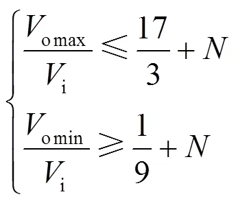

LLC谐振变换器不需要调节电压,其增益应保持恒定,则有[24]

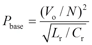
LLC谐振腔的设计只有品质因数和电感比两个自由度[25],实际上
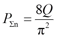

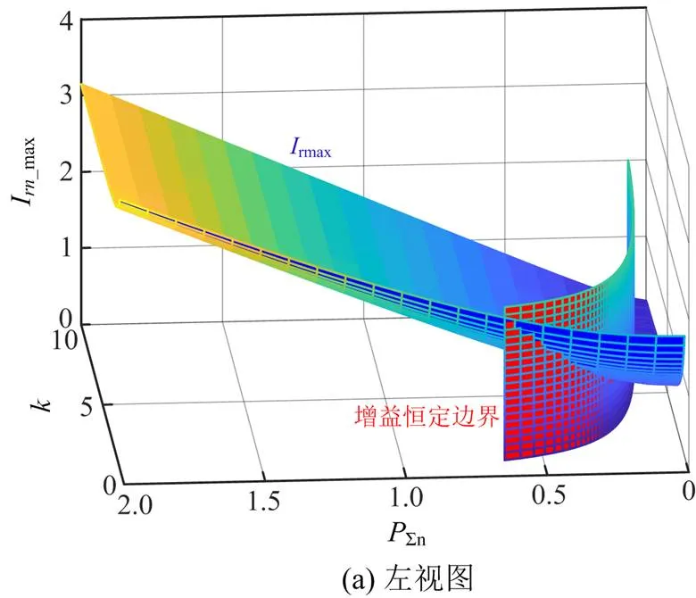
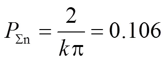


对于buck-boost变换器,只需要设计电感b的值,根据以上分析,电流b连续的条件为
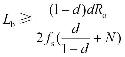
4 仿真与实验验证


图12 d = 0.1时的仿真波形

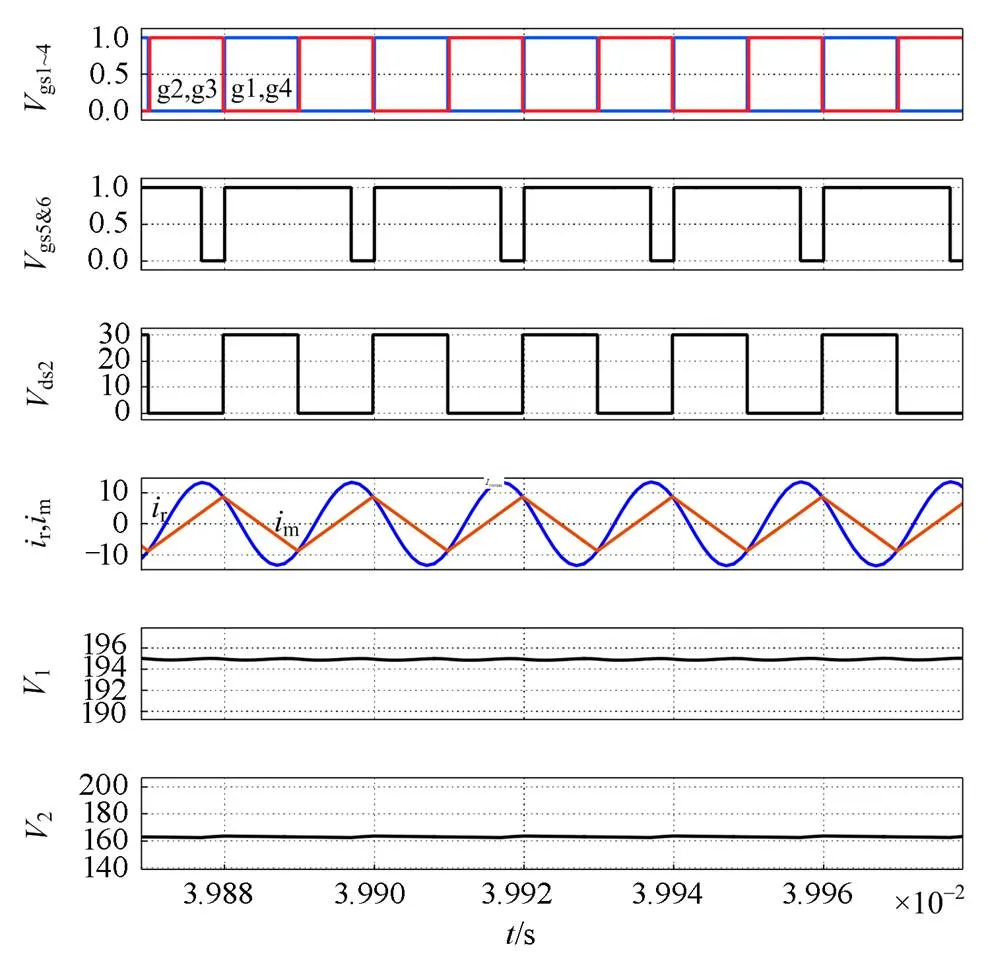
图13 d = 0.85时的仿真波形
图14为实验样机照片,样机参数如表2所示。

图14 实验样机照片
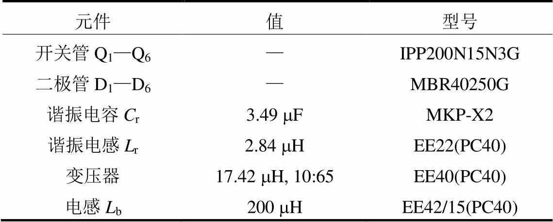
表2 元件参数

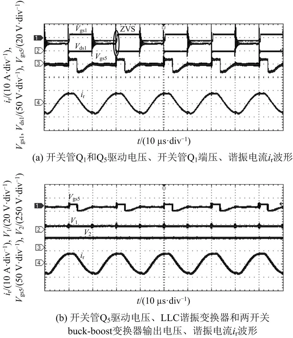
图15 d = 0.1时的实验波形

图17为两开关buck-boost输出电压2突变的实验波形,可见其迅速达到稳定值。
图18为实验样机的测量效率,随着占空比的增大,样机输出总功率增大,效率微微上升,随着LLC谐振变换器的传输效率占比略微下降,整机效率开始下降,但仍保持在较高值,样机最高效率为97.4%。

图16 d = 0.85时的实验波形

图17 V2突变实验波形

图18 实验样机效率
5 结论
本文提出了一种宽增益高效率LLC谐振变换器,由LLC 谐振变换器和两开关buck-boost变换器采用输入并联、输出串联的方式得到,其具有以下特点:
1) 开关频率固定于谐振频率,有利于磁性元件的优化设计;
2) 通过改变两开关buck-boost的占空比调节输出电压,调制方式简单;
3) LLC谐振变换器运行于谐振频率,传输变换器的大部分功率,变换器获得了高效率。
[1] SHANG M, WANG H. A LLC type resonant converter based on PWM voltage quadrupler rectifier with wide output voltage[C] // IEEE Applied Power Electronics Conference and Exposition, March 26-30, 2017, Tampa, Florida, USA.
[2] WEI Y, LUO Q, WANG Z, et al. A complete step-by-step optimal design for LLC resonant converter[J]. IEEE Transactions on Power Electronics, 2021, 36(4): 3674-3691.
[3] FOROUZESH M, SIWAKOTI Y P, GORJI S A, et al. Step-up DC-DC converters: a comprehensive review of voltage-boosting techniques topologies and applications[J]. IEEE Transactions on Power Electronics, 2017, 32(12): 9143-9178.
[4] BADAL F R, DAS P, SARKER S K, et al. A survey on control issues in renewable energy integration and microgrid[J]. Protection and Control of Modern Power Systems, 2019, 4(1): 87-113.
[5] 孙立明, 杨博. 蓄电池/超导混合储能系统非线性鲁棒分数阶控制[J]. 电力系统保护与控制, 2020, 48(22): 76-83.
SUN Liming, YANG Bo. Nonlinear robust fractional- order control of battery/SMES hybrid energy storage systems[J]. Power System Protection and Control, 2020, 48(22): 76-83.
[6] 孙元岗, 同向前, 李庚, 等. 一种双向谐振型高频直流变压器通用参数设计方法[J]. 电力系统保护与控制, 2021, 49(5): 29-35.
SUN Yuangang, TONG Xiangqian, LI Geng, et al. A generalized parameter design approach for bidirectional resonant high frequency DC transformers[J]. Power System Protection and Control, 2021, 49(5): 29-35.
[7] 慕昆, 齐红柱, 何国锋. 基于 LLC 谐振变换器的直流电源控制系统设计[J]. 电力系统保护与控制, 2020, 48(6): 152-157.
MU Kun, QI Hongzhu, HE Guofeng. Design of DC power supply control system based on LLC resonant converter[J]. Power System Protection and Control, 2020, 48(6): 152-157.
[8] 唐忠, 白健, 赖立. 基于IPOS双LLC谐振变换器的恒压恒流充电研究[J]. 电力系统保护与控制, 2021, 49(24): 88-95.
TANG Zhong, BAI Jian, LAI Li. Constant voltage and constant current charging based on an IPOS dual-LLC resonant converter[J]. Power System Protection and Control, 2021, 49(24): 88-95.
[9] 张永明, 林嘉伟, 陈俊尧, 等. 计及DCM的电动汽车充电机LLC谐振变换器参数设计与优化[J]. 电力系统保护与控制, 2020, 48(2): 150-156.
ZHANG Yongming, LIN Jiawei, CHEN Junyao, et al. Parameter design and optimization of LLC resonant converter in electric car charger based on DCM analysis[J]. Power System Protection and Control, 2020, 48(2): 150-156.
[10] SHRIVASTAVA A, SINGH B. LLC series resonant converter based LED lamp driver with ZVS[C] // IEEE Fifth Power India Conference, December 19-22, 2012, Haryana, India.
[11] GUO W, BAI H, SZATMARI-VOICU G, et al. A 10 kW 97%-efficiency LLC resonant DC/DC converter with wide range of output voltage for the battery chargers in plug-in hybrid electric vehicles[C] // IEEE Transportation Electrification Conference and Expo,June 18-20, 2012, Dearborn, MI, USA.
[12] ABBASI M, EMAMALIPOUR R, MASOOD CHEEMA M A, et al. A constant frequency step-up resonant converter with a re-structural feature and a PWM-controlled voltage multiplier[C] // IEEE Applied Power Electronics Conference and Exposition, June 14-17, 2021, Phoenix, AZ, USA.
[13] WEI Y, MANTOOTH A. A flexible LLC topology for wide voltage gain range application[C] // IEEE 12th Energy Conversion Congress & Exposition, May 24-27, 2021, Singapore, Singapore.
[14] WU H, LI Y, XING Y. LLC resonant converter with semiactive variable-structure rectifier (SA-VSR) for wide output voltage range application[J]. IEEE Transactions on Power Electronics, 2016, 31(5): 3389-3394.
[15] ABBASI M, EMAMALIPOUR R, MASOOD CHEEMA M A, et al. An interchangeable soft-switched voltage boosting circuit for a multi-mode LLC step-up converter module in medium voltage applications[C] // IEEE Energy Conversion Congress and Exposition, October 11-15, 2020, Washington DC, USA.
[16] KIM M, JEONG H, HAN B, et al. New parallel loaded resonant converter with wide output voltage range[J]. IEEE Transactions on Power Electronics, 2018, 33(4): 3106-3114.
[17] HU H, FANG X, CHEN F, et al. A modified high- efficiency LLC converter with two transformers for wide input-voltage range applications[J]. IEEE Transactions on Power Electronics, 2013, 28(4): 1946-1960.
[18] SHAHZAD M I, IQBAL S, TAIB S. A wide output range HB-2LLC resonant converter with hybrid rectifier for PEV battery charging[J]. IEEE Transactions on Transportation Electrification, 2017, 3(2): 520-531.
[19] WANG H, CHEN Y, FANG P, et al. An LLC converter family with auxiliary switch for hold-up mode operation[J]. IEEE Transactions on Power Electronics, 2017, 32(6): 4291-4306.
[20] KIMB, PARK K, MOON G. Asymmetric PWM control scheme during hold-up time for LLC resonant converter[J]. IEEE Transactions on Industrial Electronics, 2012, 59(7): 2992-2997.
[21] 缪哲语, 仝昊, 姚文熙, 等. 一种柔性多模态宽范围全桥LLC变换器控制方法[J]. 中国电机工程学报, 2022, 42(2): 747-761.
MIU Zheyu, TONG Hao, YAO Wenxi, et al. A flexible variable-mode control method for wide-range full-bridge LLC converter[J]. Proceedings of the CSEE, 2022, 42(2): 747-761.
[22] FU D, LEE F C, LIU Y, et al. Novel multi-element resonant converters for front-end DC/DC converters[C] // IEEE Power Electronics Specialists Conference, June 15-19, 2008, Rhodes, Greece.
[23] WU X, CHEN H, QIAN Z. 1-MHz LLC resonant DC transformer with regulating capability[J]. IEEE Transactions on Industrial Electronics, 2016, 63(5): 2904-2912.
[24] FANG X, HU H, SHEN Z J, et al. Operation mode analysis and peak gain approximation of the LLC resonant converter[J]. IEEE Transactions on Power Electronics, 2012, 27(4): 1985-1995.
[25] LAZAR J F, MARTINELLI R. Steady-state analysis of the LLC series resonant converter[C] // IEEE Applied Power Electronics Conference and Exposition, March 4-8, 2001, Anaheim, CA, USA: 728-735.
[26] 孙欣楠, 陈敏, 李博栋, 等. 基于电感比分析的CLLC谐振变换器效率优化[J]. 中国电机工程学报, 2021, 41(8): 2825-2834.
SUN Xinnan, CHEN Min, LI Bodong, et al. Efficiency optimization of CLLC resonant converter based on analysis of the ratio of inductances[J]. Proceedings of the CSEE, 2021, 41(8): 2825-2834.
LLC resonant converter topology with wide gain and high efficiency
XIA Xiao1, GONG Chunyang2, BAO Jun3, ZHU Guozhong4, WANG Zhixin1
(1. School of Electronic Information and Electrical Engineering, Shanghai Jiao Tong University, Shanghai 200240, China;2. Shanghai University of Electric Power, Shanghai 200090, China; 3. Shanghai Xilong Technology Co., Ltd., Shanghai 201517, China; 4. Shanghai Chint Power Co., Ltd., Shanghai 200210, China)
There are shortcomings of an LLC resonant converter with strong gain load sensitivity and strong coupling with efficiency. Thus this paper proposes a wide-gain and high-efficiency LLC resonant converter topology composed of LLC resonant converter and a two-switch buck-boost converter. Using parallel connection and output series, the LLC resonant converter transmits power and the buck-boost adjusts the output voltage. The LLC resonant converter operates at the resonant frequency, and uses PWM for the buck-boost to regulate the output voltage. The operation mode of the proposed converter is analyzed, the corresponding parameter design method is given, and the simulation verification is carried out. Finally, experiments are carried out on prototypes with input 30 V, output 200~360 V, and 360 W, and the gain range and efficiency of the experimental prototype are 6.67~12 and 97.4%, respectively. Simulation and prototype experiments verify the effectiveness of the proposed wide-gain and high-efficiency LLC converter topology and its modulation method.
wide gain; high efficiency; LLC resonant converter; resonant frequency; two-switch buck-boost converter
10.19783/j.cnki.pspc.220478
国家重点研发计划项目资助(2018YFB1503000, 2018YFB1503001;上海市科委科技计划项目资助(21DZ1207300)
This work is supported by the National Key Research and Development Program of China (No. 2018YFB1503000 and No. 2018YFB1503001).
2022-04-06;
2022-06-04
夏 潇(1998—),男,硕士研究生,主要研究方向为电力电子技术;E-mail: xiaxiao@sjtu.edu.cn
王志新(1964—),男,通信作者,教授,博士生导师,主要研究方向为电力电子技术。E-mail: wangzxin@ sjtu.edu.cn
(编辑 魏小丽)
