Multi-objective optimization of frequency and damping of vertical stabilizer skin structure placed with variable-angle tows
2023-02-09LeiZUXinzhoXIAQinZHANGGuimingZHANGShijunCHENJinhuiFULichunZHOUHubiWANGDeboLILiqingZOU
Lei ZU, Xinzho XIA, Qin ZHANG,*, Guiming ZHANG, Shijun CHEN,Jinhui FU, Lichun ZHOU, Hubi WANG, Debo LI, Liqing ZOU
a School of Mechanical Engineering, Hefei University of Technology, Hefei 230009, China
b Anhui Province Key Laboratory of Aerospace Structural Parts Forming Technology and Equipment, Hefei University of Technology, Hefei 230009, China
KEYWORDS Damping;Fundamental frequency;Multi-objective optimization;Variable-angle tow;Vertical stabilizer skin;Vibration properties
Abstract The vibration characteristics of composite vertical stabilizer skin structures play a critical role in damping effects designed for overcoming the air disturbances experienced by aircraft structural components during flight. The first-order fundamental frequencies and their corresponding damping characteristics of the vertical stabilizer skin structure tow-steered by automatic fiber placement technique were optimized with the parameterized trajectories and plies as design variables.Firstly,the vibration and damping numerical models were derived based on Kirchhoff laminate theory, the Rayleigh-Ritz method, and the Strain Energy Method. Then the optimization model was developed by adopting the self-adaptive Differential Evolution Multi-objective optimization algorithm and incorporating the solution method of Pareto Front.The constraints of this optimization model considered the experimentally obtained minimum turning radius of prepregs tow-steered in automatic fiber placement process obtained from experimental tests. Finally, the comparison of numerical simulation results was conducted for the optimized trajectories and the conventional straight trajectories under various boundary conditions, and the numerical results were partially validated through damping and frequency tests. The results indicate the vibration characteristics of the composite vertical stabilizer skin structure can be enhanced to a large extent by optimizing fiber trajectories, and the enhancement percentage is affected by the boundary conditions of the actual structure.
1. Introduction
Carbon Fiber Reinforced Plastics (CFRP) have been increasingly used in aerospace,new energy and defense fields for their superior specific strength, specific stiffness, and fatigue durability compared to metals.1-3CFRP is a kind of strong anisotropic material with strong designability capable of meeting specific requirements through deliberate design by changing the properties of material constituents, layup angle and number of plies.For this reason,a large number of research works have been devoted to their structures design and optimization,focusing mainly on reducing redundant weight and enhancing mechanical properties, etc. For some aircraft structural components, there are strict requirements for their strength, even their dynamic performance has become key indicators, such as structural damping effect.4
Generally, it is not difficult to obtain the stress uniformity of structures laid up by the design of fiber linear stacking.The recent emergence and development of new manufacturing technologies such as Automatic Fiber Placement(AFP)largely make it possible to further improve structural mechanical behaviors of CFRPs.5Such an improvement is based on the fact that AFP can manufacture Variable-Stiffness Composite(VSC) laminates, or so-called Variable-Angle Tow (VAT)/Tow-Steered (TS) laminates.6,7Compared to the traditional laminates, namely Constant Stiffness Composite (CSC), VSCs can provide more design parameters due to variety of trajectory patterns, which expands the design space for researchers to optimize more design objectives, such as the buckling,aeroelastic,and vibration performance.8-11In an AFP process,the prepreg tows are placed on the mold in a given trajectory through guidance by the fiber spreading head mounted on a machine or robot.However,when the prepreg is laid in a curve through the AFP, defects such as wrinkles, overlaps and gaps usually occur in the prepreg and thus causing strength reduction of VSCs.1,12The width and thickness of the prepreg have influential effects both on its ultimate turning radius and the trajectory design of the VSC,which in turn directly determines the overlaps and gaps.Therefore,an optimization of VSC fiber trajectories and structures is supposed to consider fiber turns,overlaps and gaps according to the intrinsic characteristics of the filament prepregs and the AFP equipment used.
At present, composite laminates are widely used in some aircraft structural components, such as fuselages, inlets, wings of airplane and vertical stabilizer skins. As a result of the disturbing effect by air friction during flight,the modal characteristics design of aircraft is particularly essential. The service environments require the fundamental frequency and damping of structural components are as large as possible, thereby reducing the vibration amplitude of aircraft.
When it comes to laminate vibration characteristics, some studies have devoted to solving and optimizing the fundamental frequencies characteristics of CSC and VSC.13-15Due to the anisotropy of CFRP, it is difficult to obtain the analytical solution of fundamental frequency of laminates;16therefore,Finite Element Method (FEM) has become the main method in existing literature.17Besides the well-known FEM, various approximate and numerical methods, such as the Rayleigh-Ritz method, the Differential Quadrature Method (DQM),and the Discrete Singular Convolution (DSC) method, have also been used to obtain solutions for composite structures.18,19Among these methods, DQM, as a numerical solution method,18,20is one of the most widely used methods having received considerable attentions from scholars because of its relatively high computational efficiency. Chen et al.14analyzed the free vibration of cross-ply laminated beams combining the state space method. Chen and Lu¨15studied threedimensional free vibration of cross-ply laminated plate with one pair of simple supports at adjacent edges. Wang et al.21studied simply supported anisotropic rectangular plates by the DSC method and analyzed the nonlinear static responses of composite laminated plates. Wei22and Zhao23et al. used the DSC algorithm to analyze the high frequency vibrations of composite laminates under irregular support.Abdalla et al.24maximized the fundamental frequency with the laminate parameters as design variables, resulting in an improvement of over 12% compared to conventional designs. In another paper,25the authors proposed a new method to increase the fundamental frequency of composite plates. The results show that, for completely fixed boundary conditions, the optimized composite plates could provide a fundamental frequency 13.3% higher than that of conventional plates. Falco´ et al.26further maximized the fundamental frequency of the laminate using a high order polynomial as the trajectory of the laminate,and the fundamental frequencies respectively increased by 16%, 28% and 36% for different boundary conditions. The authors pointed out that the complexity of the fiber trajectories should be considered in design for it might cause difficulties in the manufacturability of the panels.
Damping is another important dynamic feature for vibration performance. The damping level of composites is generally much larger than that of commonly used metallic materials, and the viscoelasticity of their polymer matrix is the main contributor to damping.27Recently, dissipation mechanisms of fiber-reinforced resin matrix composites and the development of numerical models for estimating damping levels have attracted the interest of many scholars.28,29Ref. 28 reviewed the damping mechanism of fiber reinforced resin matrix composites. Chandra et al.30analyzed different sources of damping in fiber-reinforced composites, including viscoelasticity of the matrix and fibers, fiber-matrix interaction,evolution of damage,visco-plasticity effects and thermoelastic phenomena. In addition, characterizing structural damping is also critical, and the main existing methods are classical phenomenological linear-viscoelastic models, such as the Kelvin-Voigt, Maxwell or Zener models, and the complex modulus approach.7Besides these methods, the numerical modeling method used most often is the Strain Energy Method(SEM)which enables to estimate the Specific Damping Capacity(SDC)corresponding to each vibration mode.31The principle of SEM method is: the dissipated energy is decomposed into components corresponding to each strain component,and the ratio between the stored and dissipated energy for each vibration mode is the SDC for the corresponding mode. The SEM has been used in numerous studies to predict modal damping of thin conventional laminates.6,7,32-34The structural damping level can be adjusted by appropriate manipulation of the material and geometric properties of the composite laminate,and some investigations29,35have been conducted on this.However,the current research mainly has problems,viz.insufficient consideration of structural fabrication difficulties, lack of experimental validation, and large discrepancies between experimental and numerical results.35,36
Some investigations have proven that simultaneous maximization of the fundamental frequency and its corresponding damping are conflicting design objectives, which is a common problem in multi-objective optimization.6,31Based on both numerical and experimental results,Pereira et al.6,7has preliminarily validated the possibility of simultaneously adjusting the frequency and damping of rectangular laminates at variable angles. Aiming to maximize the benefits of fiber steering, this study takes the variable-angle aircraft vertical stabilizer skin structure as the research object, and defines the trajectory and layup parameters as design variables, aiming to maximize the advantages of fiber steering by simultaneously improving the modal natural frequency and its corresponding damping ratio, that is, the optimization objective. The structural model is derived based on Kirchhoff laminate theory, Rayleigh-Ritz method,and SEM;the fundamental frequencies are calculated through the finite element software ABAQUS, and the damping are calculated by combining the finite element calculation results with the SEM. The main optimization program, which is implemented in MATLAB, was written based on the selfadaptive SDEMO algorithm with considering the prepreg manufacturing constraints and solving the conflict problem between multiple objectives through the Pareto dominance concept. Numerical simulation results of VSC and conventional CSC under various boundary conditions are presented,and some numerical results are validated by comparison with experimental results.
2. Theoretical development of optimization model
2.1. Parameterization of fiber trajectories of VSC laminates
The parameterization of fiber trajectories is one of the crucial steps towards the optimization of VSC structural components in which fiber orientation angles vary with spatial positions.Various strategies can be adopted to define the fiber trajectories in VSC laminates, such as the trajectory pattern of linearly-varying fiber orientation angle, polynomial trajectory pattern, Bessel curve trajectory pattern, constant curvature trajectory pattern,and streamline trajectory pattern.It is difficult or even impossible to realize the complex trajectory patterns in industry due to limitations of the current manufacturing processes. Therefore, the classical reference path defined by Gu¨rdal et al.37for the curved placement of composite fiber was used herein, i.e., the trajectory pattern of linearly-varying fiber orientation angle. In such a trajectory pattern, the angle of prepreg tows varies linearly along the x-axis of the reference coordinate system, and the pane is evenly covered tow by tow through a parallel moving method.The move direction is set along the parallel opposite sides of the vertical stabilizer skin structure,and thus it becomes easier to divide the structure for numerical calculations. The trajectory is shown in Fig. 1 and Eq. (1), and the structure and reference coordinate system are shown in Fig. 2.

From Eqs.(1)and(2),the equation of the trajectory of the referenced path can be obtained as

Fig. 1 Fiber trajectory of VAT vertical stabilizer skin structure.

Fig. 2 Schematic of variable-angle ply and spatial coordinate system of vertical stabilizer skin structure.

2.2. Damping modelling based on SEM
According to the concept of SEM, the damping capacity of a structure is usually characterized by SDC which is defined as


For the vertical stabilizer skin of the VSL structure, due to the variation of fiber trajectories everywhere within its single ply and the oblique trapezoid shape in the surface,it is difficult to analytically or numerically calculate the off-axis stiffness coefficients matrix. According to the constitutive relation of the VSL, the dissipated energy and the total strain energy of structure can be expressed, respectively, as


Fig. 3 Process chart of calculation and iteration of the optimization.

2.3. Multi-objective optimization model
As discussed in Sections 2.1 and 2.2, this is a multi-objective optimization problem with two contradicting sub-objectives,viz. fundamental frequency and damping of laminates of a VSC vertical stabilizer skin. The Pareto Front was applied for the non-dominant solutions of this problem. It is widely used due to the availability of a group of non-dominated sets which are defined as follows: if there is no objective function that can be improved without compromising other objective functions, the present solution is called a non-dominated set or a pareto solution, and the set of non-dominated set is the so-called Pareto Front.6,38,39
Here, the objective functions are the first-order fundamental frequency and the first-order SDC associated with the VSC vertical stabilizer skin modal properties, in particular, aiming to maximize both sub-objectives. In engineering applications,it is supposed to ensure that the external excitation frequency does not approximate to the fundamental frequency as much as possible; while greater damping can accommodate the need to decrease vibration amplitude when the structure is subjected to external excitation of the same frequency as the fundamental frequency. The two sub-objectives are expressed as

where ω1and φ1are the fundamental frequencies and SDC,both of which are related to the first-order vibration properties.
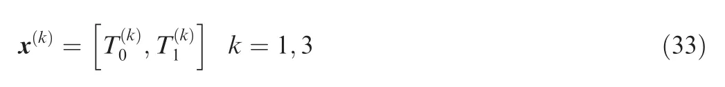
The design variable x is a vector consisting of the steering angle of the fibers in the VSC vertical stabilizer skin. According to Eq.(1)which describes the parameterization of the fiber trajectory,there are two design variables for each ply.Here the vertical stabilizer skin is a symmetric laminate, and each of its two layups is a posi-/nega-tive layer.The fiber steering angle is limited to a range from 0° to 60° considering that too large fiber steering angles can cause more serious overlap in a manufacturing process by parallel moving method.The number of plies of the vertical stabilizer skin structure here is 8, so there are a total of 4 design variables whose vectors can be expressed as
The optimization algorithm is an improved SDEMO algorithm based on business strategy.40Compared to typical Multi-Objective Evolutionary Algorithms (MOEA), this algorithm improves in the calculation of individual solution density after optimization by both considering the effect of all individuals in the population except itself and estimating all individuals in the solution set using Harmonic distance. This distance of the i-th individual solution, di, is calculated as

where di,1,di,2,···,di,kis the Eulerian distance of the i-th individual solution after de-dimension.In addition,the traditional variance factor F and the crossover probability factor CR are constants in an iteration process for optimization,while a new method of parameter adaptive adjustment is proposed to speed up convergence of optimization iteration and adapt to the demand of multi-objective evolution.
3. Numerical optimization
3.1. Optimization process
The 3D modelling and modal analysis of the VSC vertical stabilizer skin structure was carried out using the Lanczos method through the finite element software, ABAQUS. The partitioning method was used to equivalently model the continuous variation of fiber angle, with the partitioning direction along parallel edges b and c (as shown in Fig. 1); when meshing,the element aspect ratio limit and the number of elements were considered to ensure computational accuracy and computational efficiency, respectively.
The main optimization script was written based on the SDEMO algorithm and run in the commercial code,MATLAB. When calculating each set of the design variables,the main MATLAB program called Python subroutine used to modify the INP file, submit the job, and extract the resultant data; the first-order fundamental frequency of the structure,the volume of each mesh, the stress and strain components in each direction in the first-order mode of each mesh were extracted sequentially from the resultant file, and then the SDC of the structure was calculated based on SEM theory.Once all the design variables for the population have been calculated, the next generation of the population generated through crossover, variation, and selection operations, among which the selection operation is to retain the same number of Pareto Front as the number of individuals in the population at each generation(based on Pareto rank and individual solution Eulerian distance) according to the SDEMO algorithm. The process of calculation and iteration is shown in Fig. 3, where Rmis minimum turning radius of prepreg.
3.2. Turning radius test of prepregs
In the process of variable angle AFP of prepreg,the inner side of prepreg may buckle due to extrusion force,which may cause wrinkles and bridging defects. Under the experimental conditions, the relationship between the turning radius of 6.35 mm wide prepreg and placement defects was first tested by lay-up experiments with constant curvature trajectory. A constant curvature trajectory features the invariable curvature of the path, that is, the reciprocal of the turning radius always remains constant. The Ref. 41 path function of the constant curvature fiber used in the literature can be expressed as

where κ is the curvature of the reference fiber path.
The defect analysis of prepreg placement by different turning radius was carried out by MATLAB image processing technique based on the resultant images as shown in Figs. 4(a) and (c). The images were transformed by grayscale, light intensity denoising and critical value processing, etc., and the final grayscale graphs related to the placement defects are shown in Figs. 4 (b) and (d). The effective area of gray image was selected to calculate the gray point density per unit length,ρG, which is used to quantitatively characterize the prepreg placement defects, such as folds and bridges.
From the test results in Fig. 4, it is found that folding and bridging phenomenon of prepreg tows occur less when the grayscale images are controlled within 1500 gray points/mm under the condition that the minimum turning radius Rmis greater than 440 mm. Hence, the limit of placement turning radius Rmof the prepreg used in this research is 440 mm.During the optimization process, the fiber steering angle were discarded and re-generated when the corresponding turning radius did not meet the conditions (as Fig. 3).
3.3. Numerical optimization of VSC vertical stabilizer skin
The thermosetting resin-matrix carbon fiber reinforced composite prepreg used in the laminate is supplied by a company, type T300/7901, with resin content of 33%, material density of 150 g/m2, thickness of 0.15 mm and width of 6.35 mm, and the elastic constants and damping factors of the material are shown in Table 1, where G23is transverse shear modulus, ν23is poisson’s ratio of direction 23 and ρ is prepreg density. The prepreg was cured in a vacuum bagging with the curing temperature pressure profile shown in Fig. 5.The laminate material is laid in the direction shown in Fig. 1, i.e., the direction of translation is along two parallel edges, b and c, so as to have the same laying angle as the meshes in the vertical direction of the x coordinate axis have.
3.4. Optimization results

Fig. 4 Placement quality of prepregs under different turning radii.

Table 1 Basic parameters for elasticity and damping of T300/7901 prepreg.

Fig. 5 Temperature profile of curing process for T300/7901 prepreg.
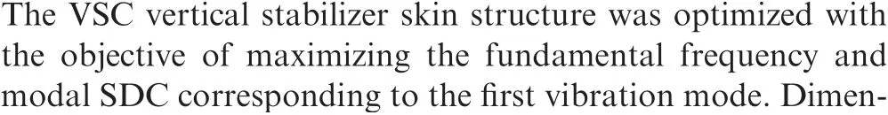
Here, VAT laminate with linear variation of the fiber path angle,is denoted as VAT-L;while constant-stiffness composite laminate with non-steered tows is denoted as CSC-N. Fig. 6 shows the initial results and the Pareto Front of and 100th generations of VAT-L under three boundary conditions (CFFF,CFCF and CCCC). For a validation by comparisons, the results of the two kinds of CSC-N, with the layer of [±30°]2sand [±45°]2s, are marked as C1-C6 as in Fig. 6. To illustrate the improvement degree of optimization and enable further comparison of the improving degree of optimization results,the optimized solutions are marked with blue circles in Fig. 5, denoted as V1-V4 for CFFF laminates, V5-V7 for CFCF laminates and V9-V12 for CCCC laminates,respectively.

Fig.6 Pareto Fronts of different boundary conditions,obtained from multi-objective optimizations to maximize fundamental frequency and SDC of the first vibration mode.
Corresponding to any point of the reference points C1 to C6 in Fig. 6, select any two points (optimization points) on the Pareto Frontier of VAT-L for comparison; any of the two parameters (fundamental frequency or modal One of SDC) of both the reference point and the two corresponding optimization points is kept the same, and the other parameter is compared.For example,taking C1 as a reference point,then its corresponding optimization points are V1 and V2;it is obvious in Fig. 6(a) that the optimization point V1 has the same fundamental frequency as that of C1,and V2 has the same first mode SDC as that of C1;the other parameter,first mode SDC for V1 and fundamental frequency for V2,was compared with that of C1, respectively. Table 2 shows the results (analyzed from in Fig. 6) of both the variation of the layup angle and the optimization of all reference and optimization points;and the optimization improvement achieved by different Pareto Fronts is shown in Fig. 7. It can be seen that, the modal SDC can be greatly improved by optimizing the fiber trajectory, and the improvement degree is greater than that of the influence on the fundamental frequencies. In addition, the improvement degree of vibration characteristics obtained by optimizing fiber angle depends on boundary conditions, and usually in this order CFFF >CFCF >CCCC.For example,comparing the CSC laminate with [±45°]2slayups, the funda-mental frequencies are increased by 10.76%,5.66%and 4.23%under the boundary conditions CFFF, CFCF and CCCC,respectively, and the modal SDC is increased by 17.80%,9.12% and 7.17% under those boundary conditions,respectively.

Table 2 Layup and vibration properties of VSC and VAT laminates of Pareto Fronts in Fig. 6.

Fig. 7 Gains achieved by different Pareto Fronts.
Fig. 8 shows the vibration properties of the 6 conventional constant stiffness laminates and their 6 optimally damped Pareto Fronts under three kinds boundary conditions in Table 2.The dissipated energies, ΔU, is subdivided into U11, U22, U33,U12, and U13; the mode SDC is subdivided into ψ11, ψ22,ψ33,ψ12,and ψ13representing the contributions of strain components ε1,ε2,ε3,γ12,and γ13,respectively.It can be seen that,ψ12,which accounts for a large proportion in the overall modal SDC, can be significantly increased by optimizing the fiber angle, thereby increasing the overall modal SDC.
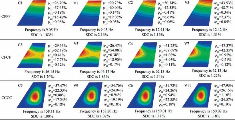
Fig.8 Vibration properties of 6 conventional constant stiffness laminates and their 6 optimally damped Pareto Fronts under three kinds boundary conditions.

Fig. 9 Prepreg curve-steered AFP machine.

Fig. 10 Production process of test laminates.
4. Experimental validation
4.1. Laminate production
To validate the optimized fundamental frequency and damping of the optimized laminate, two test laminates were produced on the prepreg curve-steered AFP machine (Fig. 9).The two test laminates correspond to C1 of CSC laminate and V2 of VAT laminate in Table 2, with the layup information as [±45°]2s, [±〈50.36°, 34.69°〉, ±〈52.67°, 43.12°〉]s,respectively.
The comparison groups, C1 and V2, for verifying the gain of the fundamental frequency were chosen since the frequency can be determined directly, while the damping was derived from the secondary analysis of the vibration curve. Here, the prepreg curve-steered AFP machine is a self-developed device for steering and pressing tow prepreg into a curved shape with a roller and kinematic system. This machine is able to quantitatively control the placement pressure, temperature, tension,rate and trajectory. Fig. 10 shows the production process of the two test laminates using T300/7901 prepreg, including automatic placement, curing, streaking, marking, cutting,and perforating.Among these steps,the laminate C1 is formed in a straight line by the technique of prepreg broadband hand gluing,and the two test samples are cured according to the curing process as shown in Fig. 5.
4.2. Experiments and its results
Fig. 11 shows the modal test using the hammer-hitting method. Nine points were selected and labeled from 1 to 9 in the excitation area in each test laminate, and a lightweight ICP sensor was installed at the signal receiving point 5. The external excitation input is exerted using the point-by-point excitation method, that is, hitting point 1-9 one by one using the hammer actuator, with each position hit 5 times; the response signals of each point were recorded and passed to the dynamic analyzer. Through the computer analysis of the collected data, the summation of the 9 points of the laminate frequency response function was obtained, and thus analyzed the first-order fundamental frequency and damping of the test laminate. The comparison of the test and analysis results is shown in Table 3. The two test results of the primary validation indicator, fundamental frequency, were both larger than those of the optimization calculation, C1 and V2, with errors of 6.52%and 8.69%,respectively; while the secondary validation indicators,SDC,were both smaller than those of the optimization calculation, with errors of 10.93% and 8.69%,respectively. The main possible reasons for such discrepancies are listed as follows:
Fig. 11 Hammer-hitting method for modal test and their test points.
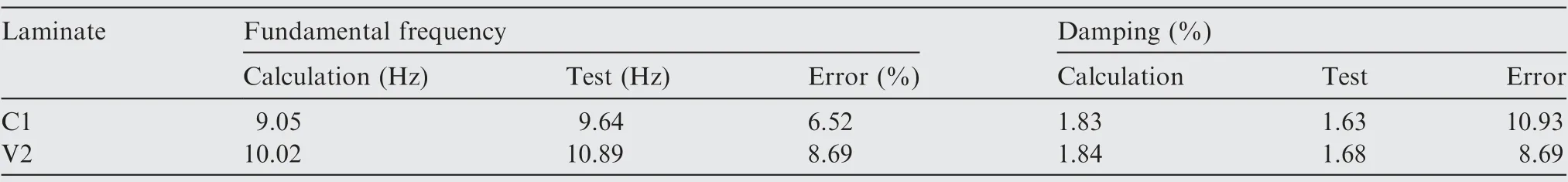
Table 3 Comparison of test and calculation results.
(1) Overlaps and gaps inevitably occur during the production of VAT laminates tested, resulting in thickness nonuniformity of laminate test pieces, while such nonuniformity was ignored in the calculation model.
(2) The idealized equivalent model is based on the theory of curvature instead of straight, whose trajectory is an approximate curve and the approximation accuracy depends on the accuracy of the laminate partition.
(3) Errors of production inevitably exist, such as trajectory deviations,curing thickness errors,and errors in the testing operation including those arising from uneven amplitude of force hammer excitation.
(4) There are errors between the basic material property parameters specified in the model and the actual ones.(5) Since the damping calculation adopts a quadratic calculation method, the error of damping is relatively large,and its accuracy depends on the fineness of the mesh division.
5. Concluding remarks
The first-order fundamental frequency and damping of the vertical stabilizer skin structure are optimized simultaneously by parameterizing the trajectory and layup sequence as design variables. With the experimental validation of partial calculated results, the conclusions are drawn as below.
(1) The turning radius has influential effects on the lay-up production quality during the placement forming process. The placement quality of T300/7901 prepreg with bandwidth of 6.35 mm at different turning radii are tested with constant curvature trajectories, and the placement defects were quantitatively characterized by MATLAB image processing. The results show that the smaller prepreg turning radius the larger the placement defects. The maximum placement turning radius of the prepreg should be 440 mm.
(2) Comparing to the traditional straight line placement strategy,the modal SDC of vertical stabilizer skin structure can be greatly improved by optimizing the fiber trajectory, indicating trajectory has greater influence than that of fundamental frequencies. In addition, the improvement degree of vibration characteristics obtained by optimizing fiber angle depends on boundary conditions, and usually in this order CFFF >CFCF >CCCC.
(3) The damping of vertical stabilizer skin structure mainly consists of damping components ψ11, ψ22, and ψ12in direction 11,22 and 12,respectively.While the damping in the direction 12, ψ12, is generally the main one to be improved when regarding improving the damping of a structure by optimizing the fiber trajectory.
Declaration of Competing Interest
The authors declare that they have no known competing financial interests or personal relationships that could have appeared to influence the work reported in this paper.
Acknowledgements
This research was co-supported by the National Natural Science Foundation of China (Nos. 51875159, 52175311,52175133,12102115,and 52005446),the Fok Ying Tung Education Foundation,China(No.171046),and the Fundamental Research Funds for the Central Universities, China (Nos.JZ2021HGTA0178 and JZ2020HGQA0197).
杂志排行

CHINESE JOURNAL OF AERONAUTICS的其它文章
- Recent developments in thermal characteristics of surface dielectric barrier discharge plasma actuators driven by sinusoidal high-voltage power
- A review of bird-like flapping wing with high aspect ratio
- Rotating machinery fault detection and diagnosis based on deep domain adaptation: A survey
- Stall flutter prediction based on multi-layer GRU neural network
- Supervised learning with probability interpretation in airfoil transition judgment
- Effects of input method and display mode of situation map on early warning aircraft reconnaissance task performance with different information complexities