Reliability analysis of arresting hook engaging arresting cable for carrier-based aircraft influenced by multifactors
2023-02-09YimingPENGYinYINPengpengXIEXiaohuiWEIHongNIE
Yiming PENG, Yin YIN, Pengpeng XIE, Xiaohui WEI,*, Hong NIE
a State Key Laboratory of Mechanics and Control of Mechanical Structures, Nanjing University of Aeronautics and Astronautics, Nanjing 210016, China
b Key Laboratory of Fundamental Science for National Defense-Advanced Design Technology of Flight Vehicle,Nanjing University of Aeronautics and Astronautics, Nanjing 210016, China
c Shanghai Institute of Spacecraft Equipment, Shanghai 200240, China
KEYWORDS Arresting cable;Arresting devices;Dynamics;Reliability;Support Vector Machines
Abstract The carrier-based aircraft landing and arrest process is complex and nonlinear, and includes the coupling effect between the aircraft and arresting system.It has many uncertain factors,which lead to difficulty in the reliability analysis.To make the reliability analysis more accurate and effective, this paper presents some studies. Taking a certain type of carrier-based aircraft as the research object,a dynamic model of the landing and arrest cable was established,and the accuracy of the model was verified using laboratory test results. Based on the model, this paper shows how the key parameters, including the sinking velocity, pitch angle and horizontal velocity, affect the collision rebound performance of the arresting hook.After that,a limit state equation of the arresting hook system’s reliability was established.For the implicit limit state equation,a surrogate model of the reliability of the arresting hook was established using the Support Vector Machine (SVM)method, and then reliability analysis was carried out using the Monte Carlo method. Finally, it was explained in detail how the key parameters affect the reliability of the hook engaging the arresting cable,and some meaningful conclusions were obtained.This analysis method and its results can provide a reference for the top-level parameter design of carrier-based aircraft and reliability research on the arresting systems.
1. Introduction
The success of an aircraft landing and arrest largely depends on the ability of the aircraft arresting hook and arresting cable.There are many factors that affect the reliability of the aircraft arresting hook and arresting cable.In addition to the complex working environment at sea, any one factor may lead to the failure of the arresting cable. According to investigation reports in previous years,the number of landing block failures caused by lanyard failure accounts for the vast majority of the total number of accidents.1Clearly, it is very important to ensure that the hook is successfully attached to the cable.
The process of landing and arrest is a multidisciplinary coupling process that has many characteristics, such as uncertain factors, high complexity, numerous failure mechanisms and low failure possibility.Yang2used a strain method to measure the arresting hook load when arresting the landing of a certain type of shipboard aircraft during a flight test and proposed two important factors affecting the reliability rate of the arrest:the length of the deck over which the arresting hook first travels before colliding with the deck and the jump height of the arresting hook. For the research on the collision rebound of the arresting hook, scholars first assumed that the hook was always close to the deck3,4during the collision process and established differential equations using the geometric motion relationship of the arresting hook to solve the rebound characteristics of the arresting hook; later, scholars introduced collision theory,5-9improved the model, established a dynamic model of the collision rebound of the arresting hook,and studied the impact the collision parameters have on the impact rebound.It was found that an arresting hook buffer can effectively control the height of collision rebound and improve the success probability of cable hanging.
Before the main landing gear wheels touch the deck, if the arresting hook does not hook a certain arresting cable,the next cable that the arresting hook encounters will be a cable that has been rolled by the aircraft wheels, and the impact of the vibration of the cable after wheel rolling on the reliability of engaging the cable cannot be ignored.3Therefore, to accurately analyze the reliability of the arresting hook and cable,it is necessary to establish not only an accurate aircraft dynamics model but also an accurate arresting cable dynamics model.The modeling methods of cable dynamics mainly include the absolute node coordinate method,10concentrated mass method,11and finite segment method.12-14For the finite segment method to establish the cable model, the dispersion is a cylinder segment connected using spring damping elements.Through dense element division, the large displacement, large deformation, large rotation and high nonlinearity of the cable can be accurately described.This method is common to establish the cable system.
Because the reliability function is implicit, the traditional first-order second moment method is not available. The analysis of the arresting process is usually done by iterating the differential equation in the time domain rather than obtaining the specific reliability function. For implicit functions, a Monte Carlo method and surrogate model method are widely used.The Monte Carlo method is simple, and the result is accurate,15-18but for a landing arrest system with low failure possibility and complexity, the calculation is very large. A surrogate model method has been widely used in implicit function reliability analysis because of its small calculation, simplicity and accuracy. Among them, the Support Vector Machine(SVM)method has a strong learning ability for small samples and outstanding generalization ability.19-22
In this paper, a dynamic model of an aircraft landing and engaging an arresting cable is established, which is verified by a landing gear drop test and arresting hook collision rebound test. Within the value boundary of each simulation parameter, the Design of Experiment (DOE) method is used to calculate the model in batches, and the sample points needed to construct the surrogate model are obtained. On this basis,the limit state equation of the cable failure probability is established, the implicit function is fitted using the SVM method to obtain a surrogate model, and the Monte Carlo method is used to calculate the reliability of the surrogate model to obtain the arrest success rate. Fig. 1 shows the reliability analysis flow of a carrier aircraft landing and arrest.
2. Dynamic model of a carrier-based aircraft landing and cable engagement
A dynamic model of an aircraft landing and arresting cable engagement is mainly based on the theory of multibody dynamics. The dynamic equation of a multibody system23can be expressed as:

where Φqis the Jacobian matrix of the constrained equation,M is the mass matrix, λ is the Lagrange multiplier, ¨q is the acceleration, F(q,˙q,t) is the force, and γ is the second derivative term of the acceleration formula.
The motion of each rigid body is described by seven generalized coordinates, [x y z e0e1e2e3]. x,y,z is global origin position, e0,e1,e2,e3are four Euler parameters. An Euler quaternion [e0e1e2e3] is used to describe the attitude of the rigid body in space, which effectively solves the matrix singularity problem caused by using an Euler angle or Kobe angle.Due to the use of independent generalized coordinates,the system dynamics equation is a highly sparse differential algebraic equation, which is suitable for efficient solution using the sparse matrix method.
Fig.2 shows an arresting hook engaging an arresting cable.The models mainly include the landing gear model, arresting hook model, fuselage model, arresting cable model and deck model. In this paper, detailed modeling of the landing gear,arresting hook and arresting cable is carried out. The interaction between the landing gear and deck, landing gear and arresting cable, arresting hook and deck, arresting hook and arresting cable is mainly considered.
2.1. Dynamic model of the aircraft landing gear
The airplane landing gear buffer studied in this paper is a single cavity variable oil hole oil gas type,as shown in Fig.3.The damping force is calculated using a classical damper model.24The strut force of the buffer includes an air spring force, oil damping force and structure limiting force.

where Fsis the buffer force,Fais the air spring force,Fhis the oil damping force, and Flis the structure limiting force.


Fig. 1 Calculation process of cable engagement reliability.

Fig. 2 Schematic diagram of an arresting hook engaging an arresting cable.

Fig. 3 Dynamic model of nose and main landing gear.
When the compressibility of the oil and the volume change of the buffer cavity are not considered,the air spring force is25:where Aais the air pressure area, P0is the initial buffer filling pressure,V0is the initial buffer filling volume,n is the variable gas index, Patmis the local atmospheric pressure, and s is the buffer stroke.
If the oil hole in the main oil chamber of the buffer is a variable oil hole and there is a side oil hole, the oil damping force is:

where ρoilis the oil density,Ahis the effective pressure oil area of the buffer, Adis the main oil cavity oil hole area, Cdis the main oil cavity oil hole shrinkage flow coefficient, Ahsis the effective pressure oil area of the buffer oil return cavity, Anis the oil hole area of the oil return cavity, and Cdsis the oil hole shrinkage flow coefficient of the oil return cavity.
The limiting force of the buffer structure Flcan be expressed as:
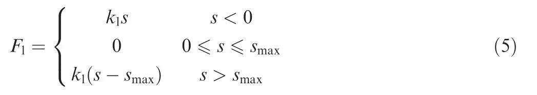
where klis the stiffness coefficient of the structural limiting force and smaxis the maximum stroke of the buffer.
Tire mechanics are an important factor affecting the landing performance of the aircraft landing gear (or the landing in general). It is very important to establish a more accurate tire force model for the accurate modeling of the entire landing gear.
The tire force model used in this paper is based on the point contact theory,26which can describe the dynamic performance of the tire, the shape of the surface and the contact of the tread. In addition to the point contact theory, the calculation method of forces in all directions of the model is as follows.
As shown in Fig.4,the tire is divided into a number of narrow strip units in the wheel disc plane. The compression area of each compression element Aiis calculated separately. For the weight coefficient Ai,the weighted average value of the center of mass coordinate vector Cpiof the compression part of each element and the direction of the weighted sum of the direction vector of the force giare calculated using the action point Cpand direction g of the vertical force of the tire, as shown in Eqs. (6) and (7).14

Fig. 4 Schematic diagram of tire normal force calculation method.

where α is the sideslip angle of the tire,αnis the saturation sideslip angle, Cαis the sideslip rigidity of the tire, Flatis the side force of the tire, and (Flat)maxis the saturation side force of the tire, which is equal to the product of the sliding friction coefficient μ and the vertical force of the tire Fnorm.
2.2. Dynamic model of the aircraft arresting hook
lating the force of the damper,Eq.(4)of the oil damping force needs to be replaced by Eq. (9), and the other formulas are consistent with the force of the landing gear buffer.

where AZhis the effective pressure oil area of the arresting hook damper and AZdis the oil hole area of the damper.
During landing,the head of the arresting hook will contact the deck over a very short time, and the contact force in this kind of collision can be simulated using a Hertz contact model.A Hertz contact model needs to satisfy three assumptions27:small deformation of the contact area; elliptical contact surface; and the contact object can be regarded as an elastic half space.
Reasonable assumptions made are:
(1) The collision time between the hook and the deck is very short, and there is no rigid motion between the two objects in the contact system.
(2) The rigidity of the hook head and deck is very large,and their deformation is small when they collide.
(3) The contact part of the hook beak is a smooth surface,so the contact surface can be approximately considered an ellipse.The contact system between the hook and deck is not like the contact between a ball and flat plate, so the general formula in28(the formula is applicable to the contact problem of any regular shape object except a parallel cylinder)in Hertz contact theory is chosen to define the collision force F between the hook and deck.

In this paper,the longitudinal buffer of the arresting hook is a single cavity constant oil hole oil gas type, without a side oil hole. The modeling of the longitudinal buffer of the arresting hook is similar to that of the landing gear buffer.When calcu-

Fig. 5 Schematic diagram of tire lateral force calculation method.

2.3. Dynamic arresting cable model
To consider the contact between the wheel and cable and the arresting hook and cable, this paper uses the finite segment method to establish an arresting cable model. The arresting cable is divided into several rigid elements along its axis. The arresting cable discrete elements have the same mass and moment of inertia attributes, as shown in Fig. 7, where m is the mass of the cable discrete element, Ixx,Iyy,Izzare the moment of inertia of the cable discrete element.The mass inertia property of the discrete element is determined by the section size and linear density of the arresting cable itself, and each arresting cable discrete element has an independent motion degree of freedom.
Linear stiffness and damping are added in the direction of the axis, in the plane of the main axis and in the section between adjacent discrete elements of the arresting cable.The stiffness and damping values are determined by the following formulas:sional rigidity of the arresting cable per unit length,and C0twistis the torsional damping of the arresting cable per unit length.


Fig. 7 Discrete element of arresting cable.
Meanwhile, the contact between the cable and deck, the contact between the cable and support, and the initial tension of the cable are taken into account when modeling the arresting cable, as shown in Fig. 8.
3. Verification of dynamic model
In this paper, the dynamic model is verified using a landing gear drop test and arresting hook collision rebound test, and the dynamic simulation results are compared with the test results. The comparison data are the key technical indices of the landing gear drop test, the collision rebound height and collision load on the arresting hook, and the accuracy of the dynamic model is verified.
3.1. Verification of dynamic model of nose landing gear

Fig. 6 Hertz contact force model.
where K0axialis the tensile rigidity of the arresting cable per unit length, lsegis the dimensionless length of a discrete element of the arresting cable, C0axialis the axial tensile damping of the arresting cable per unit length, K0bendingis the bending rigidity of the arresting cable per unit length, C0bendingis the bending damping of the arresting cable per unit length,K0twistis the tor-The dynamic simulation parameters of the falling shock are consistent with those of the falling shock test, and the sinking velocity is 6 m/s. The technical indices for comparison of the Nose Landing Gear (NLG) include the maximum stroke of the buffer, the maximum sinking at the center of gravity, the maximum compression of the tire and the peak value of the total load on the tire.The simulation results of these four technical indices are shown in Figs.9-10.The simulation results are compared with the test results, and the comparison results are shown in Table 1.
The data in Table 1 show that the error of the four main technical indices of the simulation model is less than 3%compared with the results of the drop test, which shows that the dynamic model of the nose landing gear is accurate and can be used for the dynamic model of the landing of the entire aircraft.
3.2. Verification of main landing gear dynamic model
The technical indices for comparison of the Main Landing Gear (MLG) include the maximum stroke of the buffer, the maximum sinkage at the center of gravity and the peak value of the tire load. The simulation results of these three technical indices are shown in Figs. 11-12. The simulation results are compared with the test results, and the comparison results are shown in Table 2.

Fig. 8 External forces on arresting cable.

Fig. 9 Curves of buffer stroke and displacement of the center of gravity of NLG.

Fig. 10 Curves of tire compression and single wheel load of NLG.

Table 1 Comparison of drop test results of NLG.
Table 2 shows that the error of the three main technical indices of the simulation model is less than 6%compared with the test results,indicating that the main landing gear dynamics model is accurate and can be used for the whole landing dynamics model.
3.3. Verification of dynamic model of collision and rebound of arresting hook
As shown in Fig.13,the arresting hook is installed on the side of a basket, and the basket is placed at a fixed height to simulate the sinking velocity of the arresting hook when it collides;under the arresting hook head is a high-velocity rotating disc with a coating, the collision point between the hook head and the disc is located at the edge of the disc, the disc rotates in the reverse direction of the aircraft, and the relative linear velocity between the hook head and the disc at the collision point is the same as that of the aircraft. The course velocity is the same when landing.

Fig. 11 Curves of buffer stroke and displacement of the center of gravity of MLG.

Fig. 12 Curve of tire load of MLG.

Table 2 Comparison of drop test results of MLG.
A dynamic simulation of the collision rebound of the arresting hook is carried out.The sinking velocity,engagement velocity and filling parameters of the arresting hook buffer are consistent with the collision rebound test conditions. The simulation results are compared with the test results.The technical indicators for comparison include the collision load on the hook head and the maximum height of the collision rebound,as shown in Table 3.
By comparing the simulation results with the test results,except for the contact force error of 9.67%in Case 2,the error of the results is less than 5%, which shows that the dynamic model of the collision rebound of the arresting hook in this paper is accurate and can be used for the simulation analysis of the collision rebound of the arresting hook.
4. Verification of dynamic model
Based on the dynamic model of the carrier aircraft landing and arresting cable engagement, the influence of some key parameters on the collision rebound performance of the arresting hook is analyzed, including the sinking velocity, horizontal velocity and pitch angle.
4.1. Influence of sinking velocity on arresting hook collision rebound
According to the calculation method given in Ref. [29], the average sinking velocity and the maximum sinking velocity are 3.6 m/s and 6.3 m/s, respectively. In the simulation calculation, the landing velocities of the aircraft selected in this paper are 3.6, 4, 5 and 6.3 m/s, and the curve of the rebound height of the arresting hook collision under different sinking velocities is obtained,as shown in Fig.14,where VVis the sinking velocity.
Fig. 14 shows that when landing, the height of the first bounce after collision between the arresting hook and the deck increases correspondingly with increasing sinking velocity.When the sinking velocity is 6.3 m/s, the height of the first bounce is 53 mm; because of the increase in the jumping height, the distance of the first bounce increases slightly with the increase in the sinking velocity but is not more than 4 m.
4.2. Influence of pitch angle on arresting hook collision rebound
The maximum pitch angle of the aircraft landing is 8°. The change trend of the anticollision rebound performance of the arresting hook when the pitch angle (θP) changes from 0° to 8° is analyzed. Other parameters are taken as initial values.
For the collision of the arresting hook, the change in the pitch angle mainly changes the deck angle and the collision point of the hook head. With increasing pitch angle, the deck angle of the arresting hook increases accordingly. Fig. 15 shows that the height of the first bounce after the collision between the arresting hook and the deck increases with increasing pitch angle, which is consistent with the conclusion that the rebound angular velocity of the arresting hook increases with increasing deck angle in Refs. [3-5]. When the pitch angle is 8°, the first bounce height is 81 mm, and the bounce distance is 4.57 m.

Fig. 13 Schematic diagram of test of arresting hook bounce.

Table 3 Comparison of simulation and test results.

Fig. 14 Changes in bounce height of arresting hook after impacting with different VV.
4.3. Influence of the horizontal velocity on the arresting hook collision rebound
In this paper, different horizontal velocities (VE) of 55, 50, 45 and 40 m/s are used for simulation analysis, and the other parameters take the initial value.

Fig. 15 Changes in bounce height of arresting hook after impacting with different θP.
Fig. 16 shows that the height of the first bounce after the collision between the arresting hook and the deck is almost unchanged as the horizontal velocity decreases,but the bounce distance decreases as the horizontal velocity decreases.
5. Verification of dynamic model

Fig. 16 Changes in bounce height of arresting hook after impacting with different VE.
Based on the analysis of the impact of the key parameters on the rebound characteristics of the arresting hook,the next step is to calculate and analyze the reliability of the arresting cable.In this paper, it is assumed that there is only one arresting cable on the aircraft carrier; if it is engaged, it will be successful,and if it is not engaged,it will fail.This paper only analyzes the reliability of the arresting hook and cable in the process of arresting the aircraft. The reliability of the arresting system after successful cable engagement is not the research content of this paper. That is, if the arresting system is reliable, the analysis focuses on whether the arresting hook can successfully engage the arresting cable.
During a landing, the main reasons for a failure to engage the cable are the arresting hook directly crossing the arresting cable or bouncing over the arresting cable after colliding with the deck.There are two situations for successful cable engagement: one is that the arresting cable enters the hook throat directly; the other is that the arresting cable slides into the hook throat after colliding with the hook arm.
The arresting hook and the arresting cable move in threedimensional space in the simulation process. If the relative position between the arresting hook and the arresting cable is taken as a function, the modeling is relatively complex and the error is large; therefore, the contact force between the arresting hook and the arresting cable is taken as a function,which can be used to judge whether the cable is successfully engaged. First, a contact area on the arresting hook is determined. As long as the arresting cable contacts the area, the hook can successfully engage the cable, as shown in Fig. 17.Only when the contact force between the area and the arresting cable is greater than zero is it considered that the arresting cable enters the hook throat and the cable engagement is successful.

Fig. 17 Ideal contact area of the arresting hook.
Therefore,based on the contact force between the arresting hook and cable, the reliability function of the arresting hook and cable is established as follows:

where f is the contact force between the hook and cable and x is the key parameter affecting the reliability of cable engagement.
From the expression of the reliability function, it can be seen that a suspension when f(x )>0 is successful and a suspension when f(x ) = 0 is unsuccessful.For this kind of nonlinear classification problem,this paper uses the SVM method to analyze the reliability of the arresting hook and cable.
5.1. Reliability analysis flow of SVM method
Over the past decade, as an excellent kernel modeling technique,Support Vector Machines(SVMs)have become popular in the field of machine learning and are viewed as modern tools for classification and regression.30In fact, the dynamic surrogate model of an arresting hook is a typical nonlinear classification problem.‘0'represents a failure to engage the cable,and‘1'represents a success in engaging the cable. The SVM method can deal with the nonlinear classification problem well and transform the complex nonlinear classification problem into a linear plane classification problem in high-dimensional space, but its calculation accuracy depends on the number and accuracy of the samples at the failure boundary, which is called the support vector.
A Support Vector Machine (SVM) is a linear method in a high-dimensional feature space, which is nonlinearly related to the input space.31To solve the problem of nonlinear regression,the idea of a SVM is to introduce nonlinear mapping and map the low dimension sample space into a high dimension(or even infinite dimension) feature space so that the highly nonlinear problem in the sample space can be solved by applying a SVM linear regression method in the feature space. Fig. 18 illustrates this idea intuitively.
When the feature space samples are linear, the problem of finding the optimal regression hyperplane can be reduced to quadratic convex programming.32


Fig.18 Nonlinear mapping from the regression sample space to the feature space.

where xiare the input values of the sample space.
5.2. Calculation and verification of surrogate model
The key factors affecting the reliability of the cable include the sinking velocity, horizontal velocity, pitch angle and distance between the landing position and the cable. On the premise of independent parameters,a SVM method is used to calculate the system reliability.It can be seen from the literature that the four parameters of sinking velocity, horizontal velocity, pitch angle, and distance between the landing position and cable all conform to a normal distribution, and the calculation method of the mean value and standard deviation is given.The distribution function of each parameter is shown in Table 4.
Many simulation calculations are carried out for the dynamic model of the ship’s catenary.The range of simulation conditions is the value boundary of each parameter,and it covers the failure boundary of the catenary.A total of 42000 sample points are calculated. Based on the 42000 sample points,the classification calculation of the SVM is carried out, and the dynamic simulation surrogate model of the arresting hook and cable is obtained. At the same time, the 42000 sample points are used as the verification test set.The surrogate model successfully predicts 41999 sample points, and the accuracy reaches 99.99%.The results show that the accuracy of the surrogate model meets the calculation requirements,and it can be used to calculate the reliability of the arresting hook.
5.3. Reliability analysis of arresting hook engaging cable
To study the influence of each parameter on the reliability of the cable, it is assumed that each parameter is independent of the others, and six working conditions are set for each parameter to analyze the reliability of the cable. In this paper,the influence of an independent parameter on the reliability of the cable is studied,and the average value of the other parameters is taken. The values of the different working conditions are shown in Table 5. The Monte Carlo method is used to solve and analyze the surrogate model. Random sampling is conducted for the distribution form and the distribution parameters of each variable. The number of sampling points is 1 million.
From Figs.19-22,it can be seen that within the calculation boundary of this paper,the distance between the landing position and the cable has the most clear influence on the reliability of the cable,the sinking velocity and the pitch angle have a certain influence on the reliability of the cable,and the horizontal velocity has little influence on the reliability of the cable.Fig. 21 shows that with increasing horizontal velocity, the change in cable reliability is not significant.It can be seen from Fig. 19 and Fig. 20 that with increasing sinking velocity and pitch angle, the reliability of the suspension cable decreases,and the increase in the sinking velocity and pitch angle will cause the increase in the jump height of the arresting hook,increasing the possibility of cable engagement failure. Fig. 22 shows that as the distance between the landing position andthe cable increases from near to far,the reliability of the cable increases first,then decreases and then increases.When the distance is less than 4 m, the reliability of the cable is relatively low. In this case, when the arresting hook reaches the vicinity of the cable, the hook has not yet dropped, and the closer the landing position is, the easier it is to cross the cable; when the distance is 4-6 m, the reliability is the highest, nearly 100%,and the hook has just dropped at this time, and it is easy to engage the cable; however,when the distance is 8 m,the reliability of engaging the cable is the lowest, which is due to the second bounce when the arresting hook reaches the vicinity of the cable, and because the distance from the landing position is large, the cable is rolled by the front wheel, therefore,the arresting cable is close to the deck and has not yet bounced up, resulting in a large increase in the probability that the arresting hook crosses the cable.

Table 4 Distribution function of parameters in reliability calculation.

Table 5 Parameter values under different landing conditions.

Fig. 19 Variation relationship between the reliability of engaging the cable and the sinking velocity.

Fig. 20 Variation relationship between the reliability of engaging the cable and the pitch angle.

Fig. 21 Variation relationship between the reliability of engaging the cable and the horizontal velocity.

Fig. 22 Variation relationship between the reliability of engaging the cable and the distance between the landing position and cable.
6. Conclusions
In this paper,a dynamic model of the landing and engagement of an arresting cable by a carrier aircraft is established and verified by experiments.On this basis,the influence of key parameters such as the sinking velocity,horizontal velocity and pitch angle on the collision rebound performance of the arresting hook is clarified. In this paper, a SVM is used to analyze the reliability of the landing and arrest systems. Within the calculation boundary of this paper, the following conclusions are obtained, and the suggestions of ideal landing conditions are given as follows:
(1) The reliability analysis shows that the distance between the landing position and the cable has the greatest influence on the reliability of the arresting hook and the cable. As the distance between the landing position and the cable varies from near to far, the reliability of the cable increases first, then decreases and then increases.The ideal landing area should be 5-66 m away from the cable;
(2) With the increase in the sinking velocity, the height of the collision rebound of the arresting hook increases,which increases the possibility of the arresting hook crossing the cable and reduces the reliability of engaging the cable. On the premise that the vertical buffer can restrain the bouncing height,the sinking velocity should be as small as possible,and it is suggested that the sinking velocity should not be greater than 4.5 m/s;
(3) With increasing pitch angle, the height of the collision rebound of the arresting hook increases,and the reliability of the suspension cable decreases.When landing,the pitch angle should be as small as possible. The recommended pitch angle is between 1° and 3°;
(4) With the increase in horizontal velocity,the height of the collision rebound of the arresting hook is almost unchanged. When the change in horizontal velocity is not large, the change in landing time is not enough to affect the reliability of the cable.If the horizontal velocity changes considerably, it may have a significant impact on the reliability of the cable, but that is not in the calculation scope of this paper, and it is not in line with the actual situation.
Declaration of Competing Interest
The authors declare that they have no known competing financial interests or personal relationships that could have appeared to influence the work reported in this paper.
Acknowledgements
This study was co-supported by the Natural Science Foundation of Jiangsu Province, China (No. BK20220910), National Natural Science Foundation of China(No.52202441),Fundamental Research Funds for the Central Universities, China(No. NT2022002), the National Defense Excellence Youth Science Fun of China (No. 2018-JCJQ-ZQ-053)., A Project Funded by the Priority Academic Program Development of Jiangsu Higher Education Institutions.
杂志排行

CHINESE JOURNAL OF AERONAUTICS的其它文章
- Recent developments in thermal characteristics of surface dielectric barrier discharge plasma actuators driven by sinusoidal high-voltage power
- A review of bird-like flapping wing with high aspect ratio
- Rotating machinery fault detection and diagnosis based on deep domain adaptation: A survey
- Stall flutter prediction based on multi-layer GRU neural network
- Supervised learning with probability interpretation in airfoil transition judgment
- Effects of input method and display mode of situation map on early warning aircraft reconnaissance task performance with different information complexities