Model-Free Adaptive Frequency Calibration for Voltage-Controlled Oscillators
2023-02-02LianghuiXieZhiQuanOsamaElnahaQinglinZhao
Lianghui Xie ,Zhi Quan ,Osama Elnaha ,Qinglin Zhao
1 Faculty of Information Technology,Macau University of Science and Technology,Macau 999078,China
2 College of Electronic Information Engineering,Shenzhen University,Shenzhen 518060,China
3 Department of Electrical Engineering,Faculty of Engineering,Assiut University,Egypt
Abstract: The operating frequency accuracy of the local oscillators is critical for the overall system performance in the communication systems.However,the high-precision oscillators could be too expensive for civil applications.In this paper,we propose a model-free adaptive frequency calibration framework for a voltage-controlled crystal oscillator(VCO)equipped with a time to digital converter (TDC),which can significantly improve the frequency accuracy of the VCO thus calibrated.The idea is to utilize a high-precision TDC to directly measure the VCO period which is then passed to a model-free method for working frequency calibration.One advantage of this method is that the working frequency calibration employs the system history of input/output (I/O)data,instead of establishing an accurate VCO voltagecontrolled oscillator model.Another advantage is the lightweight calibration method with low complexity such that it can be implemented on an MCU with limited computation capabilities.Experimental results show that the proposed calibration method can improve the frequency accuracy of a VCO from±20 ppm to±10 ppb,which indicates the promise of the modelfree adaptive frequency calibrator for VCOs.
Keywords: frequency calibration;carrier frequency offset;model-free,adaptive control;wireless communication systems
I.INTRODUCTION
Orthogonal Frequency Division Multiplexing(OFDM) has been adopted as a modulation scheme in many wireless communication standards,such as Digital Video Broadcasting(DVB)[1],Wireless Local Area Network(WLAN)[2],Narrow Band-Internet of Things (NB-IoT) [3],and so on.Meanwhile,IEEE 802.11ax and 5G wireless communication systems implement Orthogonal Frequency Division Multiple Access (OFDMA),an OFDM-based [4,5] multiple access technology.The success of OFDM is mainly due to its high spectral efficiency and ability to deal with severe propagation delay dispersion without the need for a complex channel equalizer.However,OFDM systems are very sensitive to frequency synchronization errors,known as the carrier frequency offset (CFO),which destroys the orthogonality of subcarriers[6].Consequently,the received OFDM signal suffers from many deformations including attenuation,phase rotation,and inter-carrier interference (ICI),leading to detection errors.On the other hand,a reduced CFO can effectively prolong the lifetime of communication equipments,as shown in[7,8]for NB-IoT terminal devices.A major source of CFO is the frequency mismatch between local oscillators in the transmitter and the receiver[9].Therefore,the frequency accuracy of a crystal oscillator is so important that it can affect the overall performance of a wireless communication system.
The frequency accuracy of a crystal oscillator is defined as the difference between the operating frequency and the normal frequency over the nominal frequency.In general,the accuracy values range on the scale of 10-6or 10-9relative to nominal frequency,denoted as part per-million (ppm) or part per-billion(ppb)respectively.There are many factors that affect the frequency accuracy of a crystal oscillator including load capacitance,ambient temperature,operating voltage,and so on.For example,the capacitive load applied on the crystal oscillators has an accuracy of around 5%,which leads to the frequency offset [10].Also,the aging factor of a crystal oscillator slowly alternates its operating frequency over time[11].Other imperfections originated from the manufacturing process make it impossible to ensure a completely consistent set of parameters for crystal oscillators.
These factors and others have the operating frequency vary from the nominal frequency.Such variation,even if it is small within s few ppm,could have a fatal effect on the wireless communication systems.For example,a frequency error of just 1 ppm introduces carrier frequency offsets of 2.4kHz and 5kHz for wireless communication systems working on 2.4GHz and 5GHz bands.Meanwhile,the CFO requirement of emerging wireless communication systems is becoming more and more stringent.For instance,IEEE 802.11n/ac allows a sub-carrier spacing of 312.5kHz,but the latest IEEE 802.11ax standard has a sub-carrier spacing significantly reduced to 78.125kHz[12].This evolution implies that the frequency accuracy of local oscillators is becoming more and more important.
To mitigate the effect of the aforementioned factors and deliver lower frequency offset from crystal oscillator,there are many approaches focusing on protecting the crystal oscillator from external temperature variation to increase its operating frequency accuracy.The current state-of-the-art is the oven-controlled oscillator (OCXO),which encloses the oscillator within a precisely controlled environment with constant temperature[13].Therefore,it can generate an operating frequency with an error of several ppb.Nevertheless,the constant temperature oven makes it most expensive with high power consumption for heating and thus with a large volume,limiting the use of this technique only in high-priced and special-purpose instruments.
For consumer electronics with high integration and low power consumption requirements,such as mobile phones and IoT devices,the requirement on environmental temperature is relaxed to implement a small low-cost oscillator with lower power consumption.The temperature-compensated crystal oscillator(TCXO)[11]is specially structured to compensate stress on crystal oscillators at different temperature to reduce the influence of temperature to some accepted extent.Notwithstanding,other sources of frequency offset,such as load capacitance,working voltage,and manufacturing imperfection,still affect the accuracy of the crystal oscillator.
Calibration is a cost-effective technique to improve the frequency accuracy of crystal oscillators.A voltage-controlled oscillators(VCO)can be calibrated by adjusting the voltage on its internal variable capacitor to control the generated frequency [14].In this regard,many calibration methods have been proposed in the literature.The temperature-compensated phase locked loop (TCPLL) [8] was proposed to calibrate the crystal oscillator by tuning the internal parameter of PPL based on the temperature to maintain an accurate carrier frequency.Although this method can greatly reduce the temperature impact on the carrier frequency,the TCPLL structure is complicated and the frequency characteristics at different temperatures must be known in advance.The GPS disciplined oscillator(GPSDO)offers another calibration method based on the GPS signal [15-17].When the GPSDO device first receives the GPS signal,it generates a stable one pulse per second(1PPS)signal,which is used as the reference in the local crystal oscillator.
The study in[15]uses the general unbiased FIR filter (UFIR) to filter out the noise of the GPS timing signals.Compared with the traditional Kalman filterbased GPSDO,the GPSDO based on UFIR has better robustness and accuracy.In [17],The authors proposed the Adaptive Neural-Fuzzy Inference System(ANFIS) algorithm to calibrate the crystal oscillator.In this method,control messages from the fuzzy controller can be used to train the ANFIS algorithm.In the case of GPS timing signal loss,the calibration method can still maintain the accuracy of the crystal oscillator frequency within a certain time period.Despite its high accuracy,stability,and resistance to frequency offset factors like temperature and aging,the GPSDO does not work indoor due to the unavailability of GPS signals because it requires direct line of sight to the satellites.[18] proposed calibrating the frequency by compensating the crystal oscillator inside the chip,and thus the integrated circuit of the oscillator needs to be redesigned.[19] proposed generating an accurate 1PPS signal from the micro-controller unit(MCU)by measuring the crystal oscillator period using a time-todigital converter(TDC)and adjusting the MCU counting step size accordingly,and this method thus can not be used for the VCO frequency calibration.In[20],multiple local crystal oscillators have been used as clock reference sources to calibrate the crystal oscillators,instead of using GPS timing signals.However,this calibration method is very complicated and requires a lot of calculations.
In this paper,we introduce a new frequency calibration architecture based on only TDC measurements,which are processed by a model-free adaptive control scheme to calibrate the operating frequency of the VCO by adjusting its internal voltage.The rest of the paper is organized as follows.Section II introduces the system architecture.Section III presents the proposed model free frequency calibration algorithm.The experimental results are shown in Section IV.Section V concludes the paper.
II.SYSTEM ARCHITECTURE
In this section,we introduce the system architecture of the proposed TDC-based frequency calibration scheme and analyze the factors that affect its frequency accuracy.
The proposed system architecture is shown in Figure 1.The structure is different from GPSDO in that there is no need for GPS timing signal as the reference and only TDC measurements are used during the calibration process.The proposed frequency calibration system includes a TDC,a logic controller,a digital to analog converter(DAC),a VCO and a frequency divider.As shown in Figure 1,the signal generated from the VCO is divided byNtimes into a low frequency signal.Thereafter,the TDC is used to measure the actual time period.Due to the frequency variation,there is a difference between the measured period and the nominal period of the low frequency signal.According to the measured periods,the logic controller adjusts the frequency of the VCO by controlling its voltage.
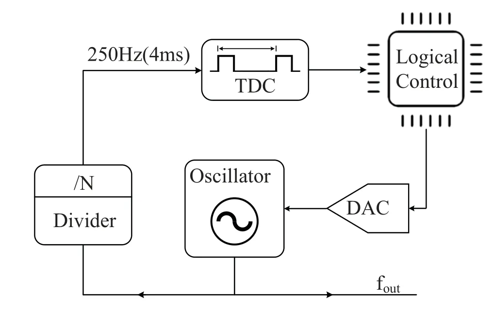
Figure 1. TDC-based frequency calibration structure.
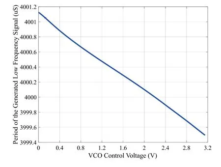
Figure 2. The period of the generated low frequency signal versus VCO control voltage.The result is measured by TDC.
Figure 2 shows the period of the generated low frequency signal measured by a TDC under different control voltages.The nominal period of the low frequency signal is 4000us.As the control voltage of the VCO increases,the period of the generated low frequency signal decreases,i.e.,the frequency of the generated signal increases.It can be observed from Figure 2 that there is a nonlinear relationship between the signal period and the VCO control voltage.The nonlinearity has a significant impact on high-precision frequency calibration.In addition,the dynamic characteristics of the VCO cause the generated frequency to shift from its nominal value gradually.Thus,the proposed calibration scheme needs to control the frequency offset of the VCO within a specific range under such nonlinear and dynamic conditions.
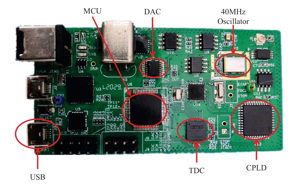
Figure 3. Experimental circuit board.
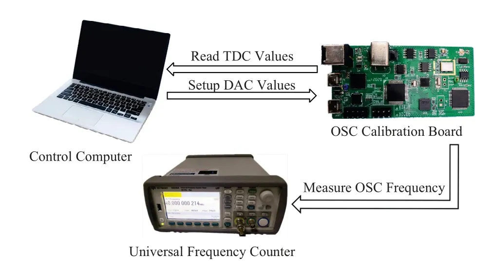
Figure 4. Experimental setup for VCO frequency calibration.
The frequency accuracy of a crystal oscillator is usually expressed

wherefmis the operating frequency,andfnis the nominal frequency.If the frequency accuracy is expressed in terms of period,(1)can be rewritten as

whereTnis the period offn,andTmis the period offm.Therein,Tmcan be measured by the TDC.However,there is a measurement errorwdue to the TDC resolution.Thus,the frequency accuracy is given by

A high-resolution TDC has a small measurement errorw.Therefore,we can see from(3)that the calibration accuracy can be improved by using a high resolution TDC or a longer measurement time periodTm.Ideally,if the resolution of the TDC is high enough or the measurement time period is long enough,we can achieve a very accurate operating frequency.However,the measurement time period is limited by the TDC range.If the measure time period exceeds the measurement range of the TDC,the result becomes inaccurate.On the other hand,although the TDC has a very high resolution,the measurement error increases when measuring long-time periods.Therefore,it is necessary to select an appropriate frequency division factor with respect to the TDC to achieve the expected frequency accuracy.In order to balance the measure time period and the measurement resolution,we choose the measure time period to be 4ms.In this manner,the measurement time period is long enough,and the TDC has enough resolution.
III.MODEL-FREE ADAPTIVE FREQUENCY CALIBRATION
In this section,we introduce the proposed model free frequency calibration algorithm,which is based on the equivalent linear model of a nonlinear dynamic system.
3.1 Dynamic Linearization Data Model
We express the relationship between the VCO control voltage and the period of the generated low frequency signal as a general discrete-time system,

whereu(k)andy(k)are the VCO control voltage and the period of generated low frequency signal at thekth time instant,respectively.nyandnuare two unknown integers,representing the order of the system.f(·) is an unknown nonlinear function.The system in(4)is called the nonlinear autoregressive exogenous(NARX) model [21].As can be seen from (4),this model is only based on the input and output historical data of the system,and does not need the internal state information.The NARX model has been widely used in neural networks and became one of the most widely studied models in neural networks.
For some complex nonlinear systems,the ordernyandnushould be chosen appropriately.In this paper,the relationship betweenyanducan be expressed as a slow time-varying nonlinear system,i.e.,

For a nonlinear time-varying system,we can transform it into a dynamic linear system under the following two conditions:
1.The partial derivatives off(·) with respect to VCO control voltageu(k)are continuous.
2.The nonlinear functionf(·)satisfies the generalized Lipschitz condition,i.e.,
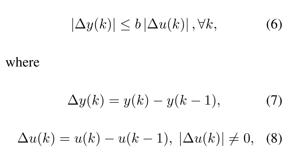
andbis a positive constant.
For a physically realizable system,these two conditions are reasonable.As the change rate of VCO control voltageu(k) is always finite,we can reasonably assume that the derivative off(·)with respect tou(k)is continuous.In addition,for a stable system,if the input is bounded,the output produced is also bounded.
For a system that satisfies these two conditions,we can transform it into a dynamic linear system,i.e.,

whereϕ(k) is called the pseudo-partial derivative (PPD),ϕ(k) is a time-varying parameter,and|ϕ(k)|≤b.For similar proof,please refer to[22-24].
From (9) we can see that a complex nonlinear system can be simplified into a dynamic linear system.The dynamic features of a nonlinear system,such as nonlinear,time-varying characteristics,etc.,are incorporated into one parameterϕ(k).Therefore,the dynamic characteristics ofϕ(k) could be very complicated and difficult to describe mathematically,but its numerical behavior can be calculated.
3.2 Frequency Calibration
The proposed model-free calibration method iteratively reduces the error between the signal period and a target valuey*using the historical input and output data.As discussed above,ϕ(k) represents the timevarying characteristics of the system atk-th time instant.If we know the time-varying characteristics of the system at timek-th instant,then we can estimate the VCO control voltage.There are many different methods to estimateϕ(k).In this paper,we use a modified projection algorithm to estimateϕ(k).The criteria function of PPD is defined as


whereη ∈(0,1]is the step length constant.This parameter is added to make the algorithm more flexible.In order to enable the algorithm to have stronger timevarying tracking ability,and guarantee|Δu(k-1)0,we use the following reset method,i.e.,

whereϕ(1)is the initial value of PPD andεis a small positive constant.
After estimating the PPD,we know the characteristics of the system at thek-th time instant,and we can further estimate the inputu(k)using this characteristic.For a given target valuey*,the proposed scheme finds an input valueu(k),at which the outputy(k)is as close toy*as possible.Consider the following criterion function,

wherey*is the target value,λ >0 is a weighting factor used to restrict the changing rate of theu(k),a reasonableλvalue makes the system more stable and with better output performance.Solving the optimal condition
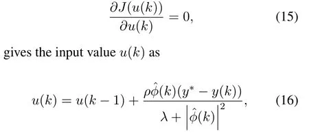
whereρ ∈(0,1] is the step-length constant to make (16) more general.The weight factorsλandµcontrol the convergence speed of the system outputyto the target valuey*.Therefore,the proper selection of these parameters makesyconverge toy*faster.The step-length constantsµandρare added to make (12)and (16)more general and more flexible[25].
After a few iterations,the output valuey(k) will gradually converge to the target valuey*.
IV.EXPERIMENTAL RESULTS
In this section,we experimentally evaluate the performance of the proposed model free adaptive frequency calibration scheme.The experiments are carried out in an environment with almost constant temperature,and the measurement results of the TDC are relatively stable.
The system architecture is illustrated in Figure 1,and the experimental verification circuit board is shown in Figure 3.The main components in the circuit board include TDC,VCO,DAC,MCU and complex programmable logic device (CPLD).The VCO has a nominal frequency 40MHz.The controllable voltage range is 0-3.15V,and the frequency adjustable range is greater than±100 ppm.Using a universal frequency counter to measure the frequency of the VCO,we found that the actual work frequency of the VCO is 39.989447939MHz and 40.007946938MHz at a control voltage of 0V and 3.15V,respectively.That is,the actual adjustable frequency accuracy range is from -260 ppm to 200 ppm,a total of 460 ppm.The DAC has a resolution of 20-bit.That is,the adjustable frequency range of each step of DAC is about 460/220 ppm=0.439 ppb.The measurement range and resolution of the TDC determine the calibration accuracy.In this experiment,the TDC chosen has a measurement range of 16s and a measurement resolution of 10ps.The CPLD is used to divide the frequency of the 40MHz signal to generate the start and stop pulse signals for the TDC measurement.We know that the higher the resolution or the longer the measurement range,the higher the accuracy of calibration.In this experiment,we find that the measurement resolution of the TDC is greatly reduced when measuring long time interval pulses.In order to balance the measure time period and the measurement resolution,we choose a measurement time period of 4ms.That is,CPLD divides the frequency of the 40MHz signal by 160000 to obtain a signal with a nominal period of 4ms.
During the experiment,we found that there is a fixed time difference between the start and stop generated by the CPLD frequency division of the 40MHz signal.When the TDC measurement value needs to converge to 3999.984480us,the actual output frequency value will approach 40MHz.This behavior is caused by the inconsistent delay of the start and stop signals in the verification circuit after the CPLD synthesis.
The setup of the entire measurement system is shown in Figure 4.According to the TDC measurement value sent by the MCU,the historical measurement value and the historical VCO control voltage,the control computer uses the proposed model free adaptive scheme to calculate the next VCO control voltage,and sends it to the MCU to adjust the output frequency of the crystal oscillator.Through iterative adjustments,the period of the generated low frequency signal is adjusted to the desired value using the proposed frequency calibration scheme.The universal frequency counter is used to verify the actual effect of frequency calibration.
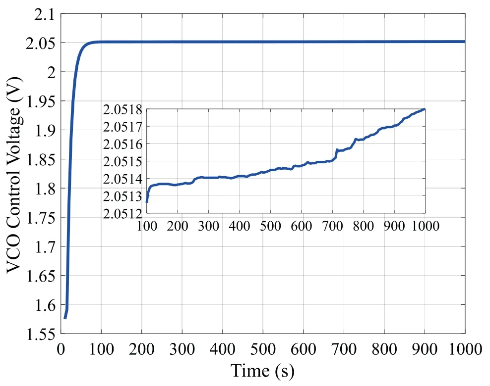
Figure 5.VCO control voltage versus time,every 5 seconds.
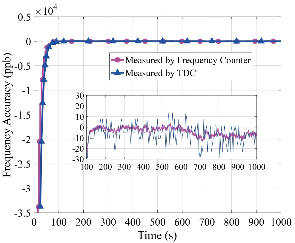
Figure 6. Calibration error versus time,every 5 seconds.
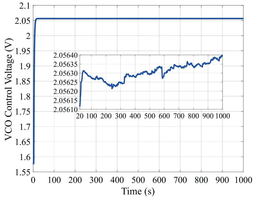
Figure 7.VCO control voltage versus time,every 1 seconds.
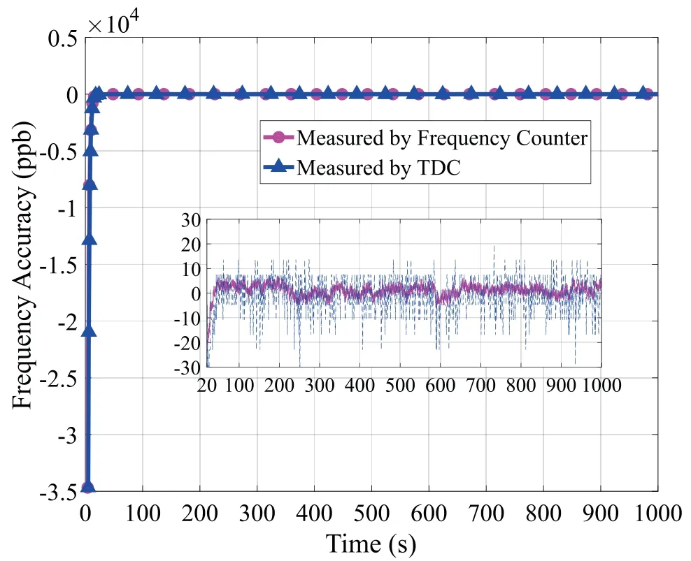
Figure 8. Calibration error versus time,every 1 seconds.
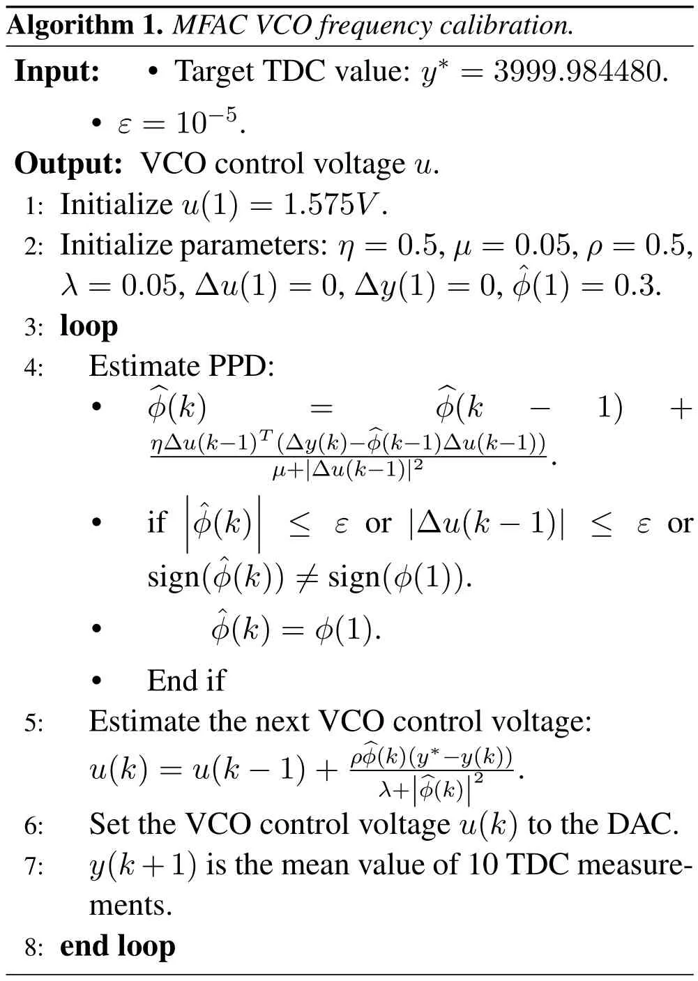
The process of the proposed model free adaptive frequency calibration algorithm is summarized in Algorithm 1,whereu(1),ϕ(1),Δy(1),Δu(1)are the initial values of the system,andη,µ,ρ,λare the parameters to be optimized.Usually,the frequency accuracy of the VCO is very high when the control voltage is half of the maximum value,so we can use it as the initial value.The value and sign ofϕ(1)are very important for the convergence speed and the stability of the algorithm,so this parameter needs to be carefully optimized.
During calibration,in order to reduce the error of the TDC measurement,we take the average value of 10 measurements as a measurement value.The calibration process is performed every 5 seconds.Figure 5 shows the change of the VCO control voltage over time.We can see that after less than 20 calibrations,i.e.100 seconds,the VCO control voltage becomes stable.However,the VCO control voltage increases slowly over time as the state of the VCO changes.The state change of the VCO may be caused by temperature variation or other factors.The calibration accuracy is shown in Figure 6.The calibration accuracy calculated by(2)shows that the accuracy of frequency is within±30 ppb.The result of the frequency counter measurement shows that the calibration accuracy is less than±20 ppb.This is mainly due to errors in the TDC measurement,which leads to insufficient accuracy in the calculation of frequency accuracy.However,it can reflect the changing trend of the frequency accuracy.
It can be seen that the initial frequency error of VCO is greater than±30 ppm.After less than 20 calibrations,the frequency error quickly converges within±20 ppb.Even though the state of the VCO is slowly changing over time,the proposed model-free adaptive frequency calibration algorithm can track this change well and keep the calibration error within±20 ppb.
Furthermore,we reduce the iteration time from 5 seconds to 1 second,and recalibrate the VCO under the same ambient temperature of 21°C.The calibration results shown in Figure 7 and 8 indicate that the proposed model-free adaptive frequency calibration algorithm requires about 20 iterations to reduce the frequency error from±30 ppm to±10 ppb and is kept within±10ppb.
V.CONCLUSION
The state of crystal oscillators usually changes over time due to many factors,such as the oscillator imperfection,and environmental changes.Therefore,crystal oscillator calibration is a prerequisite for efficient operations of the wireless communication systems.This paper develops a new scheme for crystal oscillator frequency calibration.The proposed calibration scheme does not require an accurate mathematical model,and only uses the system I/O data to calibrate the oscillator frequency.It is a low-cost solution with a simple structure.Therefore,in GPSDO systems with limited computing performance,the proposed model free adaptive frequency calibration algorithm can be utilized.
Experimental results show that after about 20 iterations,the frequency accuracy of the VCO is reduced from greater than±30 ppm to±10 ppb.In general,the accuracy of the proposed calibration method is lower than GPSDO.This is mainly because GPSDO uses a very accurate GPS timing signal as a reference.For most wireless applications,GPS is not appropriate for indoor environment.However,In the proposed scheme,only the TDC measurements are used during the calibration process as clock reference.In[22],the two proposed methods can reach 10 ppb without using GPS timing signals.Compared with the calibration system in[22],the proposed scheme reaches the same accuracy with a simple structure and lower computational complexity.
杂志排行
China Communications的其它文章
- Coordinated Planning Transmission Tasks in Heterogeneous Space Networks: A Semi-Distributed Approach
- Secrecy Rate Maximization for 6G Cognitive Satellite-UAV Networks
- Secure Transmission in Cognitive Radio Networks Using Full-Duplex Technique with Outdated CSI
- Computation Rate Maximization in Multi-User Cooperation-Assisted Wireless-Powered Mobile Edge Computing with OFDMA
- A Novel Multi-Granularity Flexible-Grid Switching Optical-Node Architecture
- Max-Min Fair RIS-Aided Rate-Splitting Multiple Access for Multigroup Multicast Communications
