Trajectory Planning for OTFS-Based UAV Communications
2023-02-02RuiHanJiahaoMaLinBai
Rui Han ,Jiahao Ma ,Lin Bai,*
1 Tsinghua Space Center,Tsinghua University,Beijing 100084,China
2 School of Cyber Science and Technology,Beihang University,Beijing 100191,China
Abstract: Unmanned aerial vehicles (UAVs) have attracted growing research interests in recent years,which can be used as cost-effective aerial platforms to transmit collected data packets to ground access points(APs).Thus,it is crucial to investigate robust airto-ground(A2G)wireless links for high-speed UAVs.However,the A2G wireless link is unstable as it suffers from large path-loss and severe Doppler effect due to the high mobility of UAVs.In order to meet these challenges,we propose an orthogonal time frequency space (OTFS)-based UAV communication system to relief the Doppler effect.Besides,considering that the energy of UAV is limited,we optimize the trajectory planning of UAV to minimize the energy consumption under the constraints of bit error rate(BER)and transmission rate,where the Doppler compensation is taken into account.Simulation results show that the performance of OTFS-based UAV system is superior to orthogonal frequency division multiplexing(OFDM)-based UAV systems,which can accomplish transmission tasks over shorter distances with lower energy consumption.
Keywords: orthogonal time frequency space(OTFS);orthogonal frequency division multiplexing(OFDM);unmanned aerial vehicle (UAV);6G;trajectory planning
I.INTRODUCTION
In recent years,unmanned aerial vehicle (UAV) has been widely used in data collection,remote sensing,and network coverage extension,which has attracted more and more attention and research interests[1,2].Since UAVs allow easy deployment with high mobility and low operating cost,the usage of UAVs has become one of the important technologies to form flexible networks at anytime in anywhere.Meanwhile,the requirement of reliable data transmission of UAVs is increasing dramatically as the applications of UAVs grow explosively [3].Specifically,as expected in the future sixth generation (6G) use-case scenarios,UAV can be adopted to the areas of emergency rescue,disaster management,and transportation assistant[4].However,when the speed of UAVs is high,the air-to-ground(A2G)wireless link becomes unstable to guarantee the high quality data transmission[5].
To concurrently meet the requirements,i.e.,robust data transmission with high mobility,the technique of orthogonal time frequency space (OTFS) is introduced,which has substantially attracted both industrial and academic interests.OTFS was firstly proposed by Hadani R.in 2017,as a new physical layer modulation system for the fifth generation(5G)communication system [6],then other researchers followed the idea of OTFS and focused on the performance analysis of signal modulation based on OTFS and the construction of efficient receiver detection systems.
OTFS is a two-dimensional modulation scheme based on the Delay-Doppler (DD) domain [7],which can efficiently cope with the time-variant multi-path channel experienced by the orthogonal frequency division multiplexing (OFDM) communication when the speed of devices is high.The technique of OTFS spreads the information symbol waveform over the entire DD plane realized by inverse symplectic finite Fourier Transform (ISFFT) and symplectic finite Fourier transform (SFFT) to achieve the near constant channel gain even in channels with high Doppler spread [8].The Doppler spread issues with OTFS modulation have been exhaustively evaluated in the recent studies.For example,in [9],Singh P.designed and analyzed low complexity zero forcing(ZF)and minimum mean square error (MMSE) receiver detection methods for multiple input multiple output(MIMO)-OTFS systems.The authors in[10]proposed an orthogonal time frequency space with index modulation (OTFSIM) system to improve the bit error rate(BER) performance,where the information is transmitted by means of constellation symbols and index bits in the DD domain.Besides,the authors in [11]considered the transmitting antenna selection in the OTFS modulation system,where the diverse performance was analyzed.
In view of the high speed of UAV,OTFS-based modulation system can be applied to UAV communications with the aim of achieving the robust A2G wireless links and reliable data transmission.More recently,there are some research works that focus on the use of OTFS modulation on UAV systems.For instance,Hadani R.[12] proposed a positioning technique method using physical random access channel (PRACH) and OTFS modulation to establish a completely standardized transmission and reception scheme,which is capable of performing time of arrival (ToA) measurements.Moreover,the authors in [13] studied the reliability performance of a down-link time-frequency space communication system with OTFS scheme,where the UAV cooperative transmission approach was developed to compensate the huge path loss caused by long transmission distance.
Nevertheless,it is noteworthy that the energy and power of UAV are limited.In order to minimize the energy consumption of UAV,it is necessary to optimize the trajectory planning,where some data transmission issues should also be taken into consideration.There have many works focused on the trajectory planning of UAV,which can be expressed as an optimization problem[14].However,the optimization problem may not be a convex problem since the original objective function may be mathematical intractable.Many different methods have been studied to solve the nonconvex problems,e.g.,deep learning algorithm,successive convex optimization technique,and reinforcement learning algorithm [15].For instance,in [16],the effective data rate of single UAV-aided sensor network is studied by optimizing the trajectory of data acquisition,which is subdivided into discrete Markov decision process(MDP)and the Q-learning algorithm can be applied.
In this paper,leveraging the advantages of OTFS modulation,we propose an OTFS-based UAV communication system,which can improve the transmission reliability in the high-mobility scenarios.The main contribution of this paper is three-fold:
• An OTFS-based UAV communication system is proposed to relief the Doppler effect;
• In order to minimize the energy consumption of UAV,the multi-task assignment method of UAV is presented and solved by ant colony optimization(ACO)algorithm;
• The trajectory planning of UAVs is optimized under the constraints of BER and transmission rate,where the Doppler compensation is taken into account.
The rest of the paper is organized as follows.In Section II,we present the system structure and the transmission model of OTFS modulation.In Section III,we minimize the energy consumption of UAV by solving the multi-task assignment problem and trajectory planning problem.Finally,we show the simulation results in Section IV and conclude the paper with some remarks in Section V.
II.SYSTEM MODEL
In this section,we firstly present the system structure of UAV communications and the channel model of A2G wireless links,then the transmission model of OTFS modulation is given.
2.1 System Structure
As shown in Figure 1,we consider a scenario that massive devices randomly locate in a large area,while UAVs are employed as aerial platforms to collect the data packets from devices and then transmit the collected data packets to ground access points (APs).Thus,robust A2G wireless links become critical to guarantee the reliable data transmission of UAVs and enhance the data offloading.To this end,UAVs utilize the OTFS modulation to relief the Doppler effect and use the optimized trajectory planning to minimize the energy consumption in the progress of data offloading.
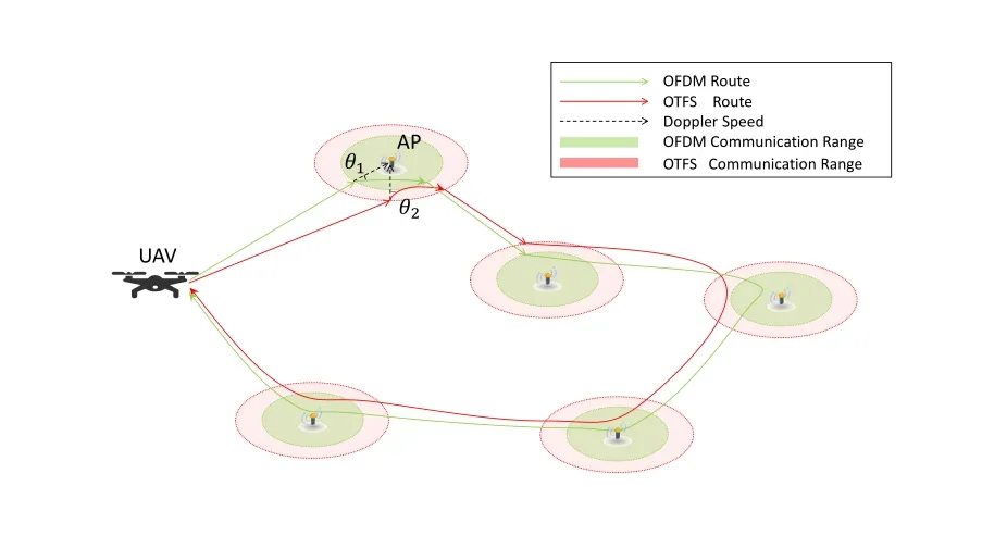
Figure 1. System structure.
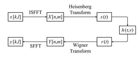
Figure 2. OTFS transmission model.
Since the obscured transmission path under the built-up urban environment that may occur between UAV and APs [17],UAVs may meet local scatterers and obstacles,a Rayleigh fading channel model of A2G wireless links is adopted,denoted by ˆH,which is shown as follows:

wheredis the distance between UAV and AP in the communication range,β0is the reference channel power gain,αis the path loss exponent,which obeys thatα≥2,Gdenotes the Rayleigh fading channel function,follows the probability density function(PDF)formula below:

wherebdenotes the received signal,σdenotes the root-mean-square of received signal.
2.2 Transmission Model
In order to meet the requirements of robust data transmission with high mobility,the technique of OTFS is applied to UAV systems.OTFS performs data modulation directly in the DD domain and extends in the whole time-frequency (TF) domain,which can achieve high reliability and high rate of data transmission in time-frequency dual selective channels [18].When appropriate receivers are used,OTFS can obtain the full channel diversity in both time and frequency.Since OTFS technology transforms the timevariant multi-path channel into DD domain,all symbols in the transmission unit experience almost the same sparse channel with slow change.Besides,the peak-to-average power ratio(PAPR)of OTFS signals is lower than that of OFDM because all modulation symbols extend evenly in the TF domain[19].In the following,we introduce the OTFS in details.
The relationship between OFDM and OTFS is given,where the time-variant impulse response can use fast Fourier transform(FFT)transform to move the data to be transmitted to TF domain and DD domain.Likewise,the signal in TF domain and DD domain can also use FFT transform to move the data to be transmitted to Doppler-variant transfer response.Besides,the TF response used in the OFDM can be transformed into the DD response used in the OTFS by using SFFT transform.The specific conversion formula can be expressed as:
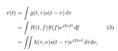
wheres(t-τ)is the signal representation in time domain andS(f)is that in frequency domain,g(t,τ)denotes the channel function in time domain,H(t,f)denotes that in TF frequency domain,h(τ,ν)ands(t-τ)denote the channel function and signal representation in DD domain,respectively.
The channel function in the DD domainh(τ,ν)can be discretized represented as[20,21]:

whereδ(*) denotes the impulse function,Mdenotes the number of resolvable paths,hmdenotes the channel coefficients in them-th path,τmdenotes the delay shifts in them-th path,νmis the Doppler shifts in them-th path.Here,the Doppler shifts can be calculated byνm=fcvm/c,wherevmdenotes the moving speed in them-th path,crepresents the speed of light,andfcrepresents the carrier frequency.
In the following,we focus on the OTFS system communication process.The flow chart of OTFS system is shown in Figure 2.Firstly,we consider the initial signals of OTFS system which is divided into coded signal blocks with periods ofN × M,wherex[k,l]represents the symbols of this block in DD domain.It means the(k,l)-th element of the modulated signal in thek-th Doppler grid and thel-th delay grid.Then,the transmitted symbol sequence in the TF domain,X[n,m],can be obtained through the ISFFT [22],as follows:

wherendenotes then-th number of OFDM symbols andmdenotes them-th number of sub-carriers.
Next,the TF domain transmitted symbol is modulated through an OFDM modulator after the domain transformation.As shown in Figure 2,we use Heisenberg Transform to transfer the TF domain signalX[n,m]into the time domain and obtain the transmitting signals(t),which can be written as:
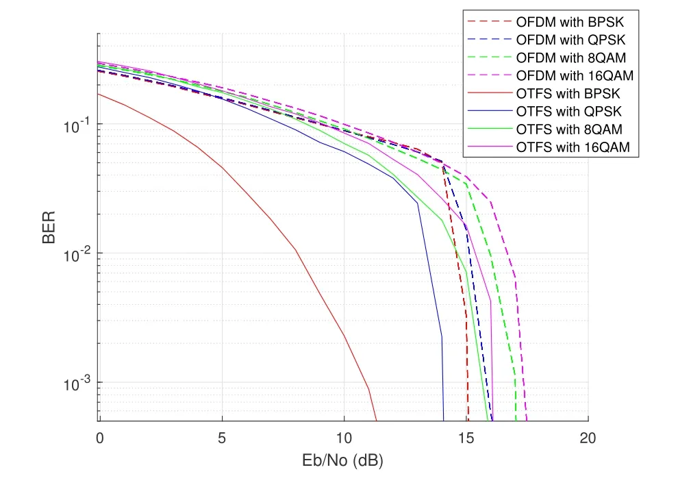
Figure 3. BER of OFDM and OTFS system performance with different modulation model.

whereg(*)denotes the sampling function of the pulse shaping filter,Δfdenotes the frequency spacing between adjacent sub-carriers,andTrepresents the TF domain time slot duration,we can also know that Δf=1/T.
According to the DD domain channel representation in Eq.(3) and assuming that the noise is additive white Gaussian noise process,the received signal can be written as:


After some mathematical calculations,the received signaly[k,l]of OTFS systems in the DD domain can be obtained through making SFFT on the received symbolsY[n,m],which can be shown as follows:

In the OFDM transmission model,the original signalX[n,m]experiences Heisenberg Transform,wireless channel with functionH[t,f],Wigner Transform and finally becomes the receiver signalY[n,m].
III.UAV MISSION ASSIGNMENT AND TRAJECTORY PLANNING OPTIMIZATION
In this section,the problem of multi-target execution order assignment is solved and then the optimization of UAV trajectory planning considering the mission requirements and UAV communication performance is presented.
The energy consumption of UAV consists of flight energyEflythat supports the movement of UAV[23]and transmission energyEtransthat allows the UAV to offload data packets to APs,which can be expressed as:
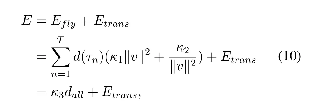
whereτnis the time slot,κ1,κ2are constant parameters decided by the UAV,vis the speed of the UAV at time slotτn,n ∈[1,T],Tis the number of time slot that the UAV experience in the trajectory,κ3is a constant parameters equals to,anddenotes the length of the total UAV trajectory.Different from ground base stations,UAV system has additional propulsion power consumption like maintaining the UAV aloft and supporting its mobility,which is usually much higher than the communication power consumption [24,25].For example,for common UAVs on the market,the operation power of the communication module is usually 0.1-2W,while the flight power is often greater than 200Weven for small UAVs,and the flight power is often 10-20kWfor some large UAVs[26].Therefore,we ignore the transmission consumption in this paper.
Since UAV has the lowest energy consumption when flying at a uniform speed [27],we assume that UAV flies at a constant speed when establishing the UAV motion model for simplicity.According to this,from Eq.(10),the energy consumption of UAV can be proportional to its flight distance,thus the energy consumption minimization problem can be simplified to thedallminimization problem.
3.1 UAV Optimal Mission Assignment
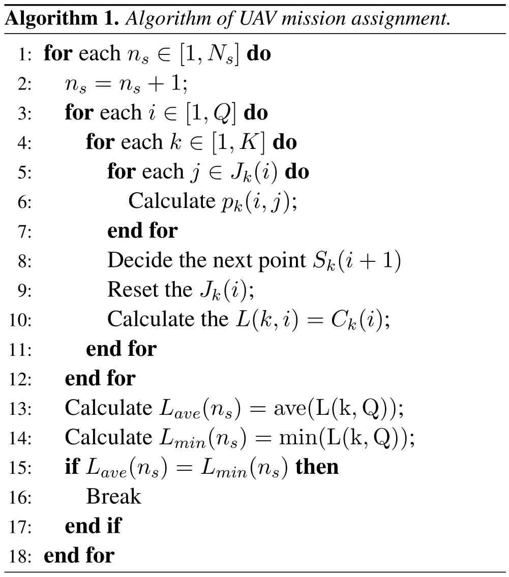
Considering that APs distribute at different location,we need to decide the completion sequence of multitasks as UAV performs communication among multiple APs,which can be equivalent to a traveling salesman problems (TSP) [28].Since ACO algorithm is adept at solving the TSP,especially combinatorial optimization problems,we use ACO algorithm to find out the shortest traversal routing among multiple APs.
To start with,we setP0as the beginning and ending point of UAV,and setPqas theq-th AP,whereq ∈[1,Q].The distance between difference points inP0and thei-th AP equals to Euclidean distance and can be written as:Dij=‖PiPj‖,whereandi,j ∈[0,Q].The UAV should traverse all APs and complete data transmission tasks.According to ACO,we assume that there areKUAVs traversing betweenP0andPiand the path memory vector thek-th UAV goes through is denoted byRk.
The construction of route of thek-th UAV communication follows the random proportional rule[29].Suppose the current AP of thek-th UAV isi,then its probabilitypkof selecting APPjas the next access object can be calculated by Eq.(11)below:

whereJk(i) represents a collection of APs which are directly reachable fromPiand not visited by thekth UAV till now,η(i,j) is a heuristic value,which is usually calculated by,andτ(i,j)represents the amount of tendency parameter on the route betweenPiandPj.
For each UAV,the path memory vectorRkrecords the serial number of APs which UAV has passed through.Then,the update of the tendency parameter amount is given by:

Here,Krepresents the number of UAVs,ρdenotes the losing rate of tendency,specified 0≤ρ ≤1,Δτkis the amount of tendency released by thek-th UAV on the line ofPiandPj,which can be given by:

whereCkis the sum of path length of UAV has gone through withpsteps,meansandp ∈[1,Q+2] denotes thep-th step which UAV has moved follows the orderRk.
According to Eq.(12)and Eq.(13),the tendency parameter update follows the steps below:
• Step 1: During the algorithm initialization,all tendency parameters of the edges of the problem space are initialized to 0.
• Step 2: With each iteration of the algorithm,tendency parameters of all paths in the problem space evaporate,and multiply all tendencies on the sides by a constant less than 1.
• Step 3: UAVs decide the next AP they are planning to move according to the probability and release tendencies on the edge to next point of this cycle,depending on the length of their path.
• Step 4: Calculate the length of the UAV goes through following the order.
• Step 5: Iterate Step 2-4 until the algorithm terminates.
The Algorithm of UAV mission assignment with maximum cycling parameter as constantNsis shown in Algorithm 1:
3.2 UAV Trajectory Planning Optimization
The purpose of UAV trajectory planning optimization is to minimize the energy consumption of UAV.Meanwhile,the optimization results should meet the constraints of the flight height of the UAV,the communication rate,and BER threshold-based communication range.
Assume that the signal source of a UAV is a constant,the signal intensity around the UAV can be calculated by:

wherePsourceis the signal power of signal resource in UAV.The corresponding signal-noise ratio(SNR)can be given by:

whereσ2is the variance of additive white Gaussian noise (AWGN).Based on the BER threshold of OFDM and OTFS communication system,which was set as 10-2,we can know the SNR value which satisfied the BER requirement under a specific Doppler speedVdoppler.Then,the corresponding communication distance thresholddrangecan be calculated by Eq.(14) and Eq.(15).Finally,the communication range of each AP can be obtained according todrange,which is a spherical space with an AP as the center anddrangeas the radius.Within this range,UAV communications can satisfy the BER threshold.
Besides,the motion state of UAV can be divided into two parts: inside the communication range and outside the communication range.When a UAV is outside the communication range,the movement of the UAV is only limited by the minimum flying altitudehminand can be regarded as a straight flight with a constant speed.When a UAV is inside the communication range,the movement of the UAV should be constrained by the speed direction and the amount of data transmitted besides the minimum flying altitude.Thus,the trajectory of UAV can be divided into two parts.We assume that the flight path of UAV intersects each signal rangeifollows the best traversing orderRat the entry pointPentry(i)and the exit pointPexit(i).The distance of trajectory of UAV outside the communication range can be calculated by:

Then,we assume that the UAV go throughSpoints inside thei-th communication range asPin(i,s),which includes the entry pointPentry(i)asPin(i,1)and the exit pointPexit(i) asPin(i,S).In this case,the distance of UAV inside the communication range is:

In this way,the whole distance of UAV trajectory can be expressed as:

where the target of the optimization can be expressed as the total distance of the UAV trajectory minimization problem that search for the minimumLtotal.
Next,we focus on the constraint when UAV is inside the communication range.Let the distance between each AP and the UAV position pointPin(i,S) asdi,sand the distance between UAV position pointPin(i,S)and its next point as Δdi,s,which are:

According to the SNR calculated by Eq.(15),we can obtain the maximum channel capacityC(d) between UAV and APs with distanced=di,s,which is expressed by:

whereWis a constant representing the channel bandwidth.
Based on Eq.(20),we assume that the maximum channel capacity betweenPin(i,s) and its next point is equal to that in distanced=di,s,then we can calculate the transmission amountMithat UAV can transmit in thei-th communication range,which should satisfy the constraintsMData,thus we can get
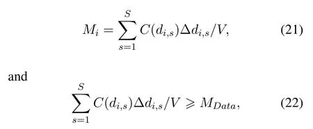
whereVdenotes a constant representing the movement speed of the UAV.
Besides,we consider the constraint of Doppler effect.Letθi,sdenote the angle between the direction of UAV movement and the line betweenPin(i,s)andPi,θi,scan be calculated by:
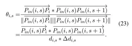
Moreover,the velocity component ofVon the line between the UAV positionPin(i,s)and the centerPishould be less thanVdoppler,which are

whereθ0=arccos(Vdoppler/V).
Consequently,the optimization problem of UAV energy consumption can be formulated as:
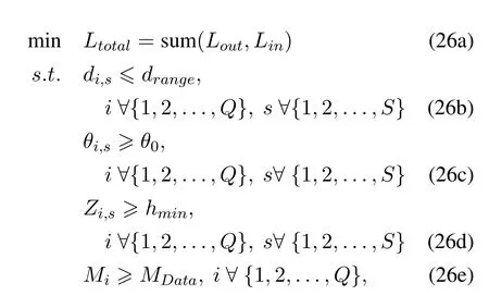
whereZi,sis the height of UAV track pointPi,s.Since the objective function Eq.(26a) is quadratic and the constraint functions Eq.(26b),Eq.(26c),and Eq.(26d)are linear,the sequential quadratic programming (SQP) algorithm can be adopted to solve this problem.
IV.SIMULATION RESULTS
In this section,we firstly present the performance comparison between OTFS and OFDM in terms of the speed of UAV and the modulation method,e.g.,binary phase shift keying (BPSK),quadrature phase shift keying(QPSK),8 quadrature amplitude modulation(QAM),16QAM,then give the simulation results of trajectory planning and optimization of OFDM and OTFS-based UAV communication systems.
4.1 Communication System Simulation Results
Figure 3 shows OFDM-based and OTFS-based UAV communication systems with different modulation model under a time-and-frequency dispersive channel and the medium Doppler corresponding to 120km/h.The dashed lines represent the performance of the OFDM system,which show that the BER of OFDM increases with the higher modulation order especially at the high SNR.They prove that the Euclidean Distance depends on modulation order has influence on the communication quality of OFDM system,thus deteriorating BER when the order increasing.Meanwhile,the solid lines represent the BER of the OTFS system with different modulation formats.Comparing the simulation results between OFDM modulation and OTFS modulation,we know that OTFS outperforms OFDM in each modulation order,particular OTFS shows a significant lower BER than that for OFDM in the BPSK modulation.Furthermore,it is indicated that the slope of the BER-SNR curve is steeper for OTFS than that for OFDM.
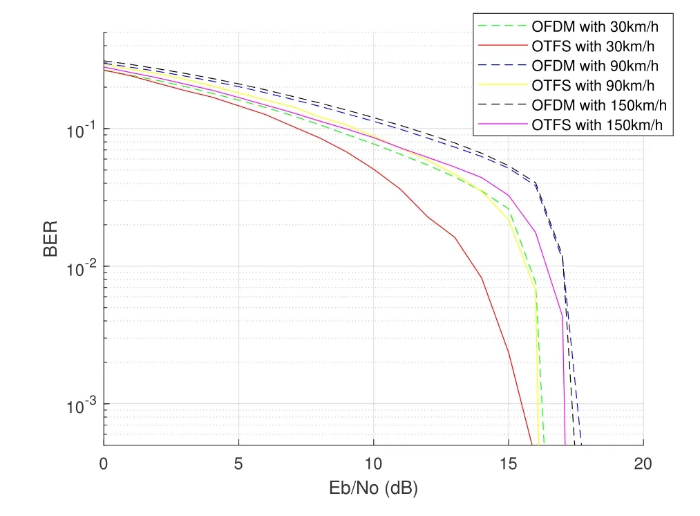
Figure 4. BER of OTFS and OFDM system performance with different speed.
In Figure 4,we compare the BER performance of OTFS and OFDM systems using 16-QAM signaling over the delay-Doppler channels with different Doppler frequencies (i.e.,with speeds of 30,90,150km/h).For OFDM-based system,the performance of BER becomes worse with the speed of UAV increasing,which implies that the Doppler frequencies of the system increases.Since the detection algorithm like message passing(MP)or minimum mean square error(MMSE)was not used to eliminate the inter code interference (ICI) and inter symbol interference (ISI),the performance of OFDM system is determined by the least constraint of subcarrier channel it experienced and therefore the BER of OFDM system with different Doppler speed were similar.As for the OTFS system,it can remain relatively constant for all transmission signal channel gain basing on the SFFT/ISFFT,which makes it affected by the Doppler effect more obvious.
From Figure 4,we can also observe that OTFS with 30km/hspeed outperforms OFDM by 3dBat BER=10-2,and the OTFS system with speed at 90km/hhas the similar performance as the OFDM system with speed at 30km/h.We also notice that as SNR increases,the difference between BER of OTFS and OFDM system also increases,which means that under same BER threshold,UAVs with OTFS system could have a higher mobile speed while transmitting signal in the same communication range,or have a larger communication range under the same speed.
4.2 UAV Trajectory Planning Optimization Results
In the simulation,the traverse mission of UAV is simulated in the task area of 10km ×10km ×1kmof the 3D topographic map,with a total of 6 APs to com-plete communication mission.The OFDM and OTFS communication systems are used for UAV’s communication channel modeling and BER results.The coordinates of starting point and APs are shown in Table 1.Besides,we calculate the different radiusdrangeof communication range of OTFS system and OFDM system with setting BER.Table 2 shows the Doppler speed and other parameters of UAV trajectory system.
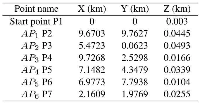
Table 1. Position of starting point and APs.
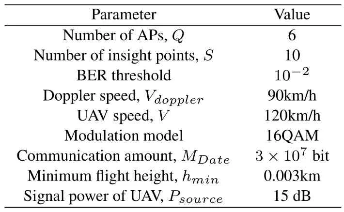
Table 2. Parameters of UAV trajectory planning.
Then,we search the shortest routing with the ACO algorithm between the starting point and APs.The initial route of OFDM and OTFS system means that the UAV flies in a straight line within communication range of APs.The red solid line and blue solid line in Figure 5 show the shortest route sequence of OFDM and OTFS system,which are both: “1-7-5-6-2-4-3-1”.The distances of OFDM initial route and OTFS initial route can be obtained,which are 32.4056kmand 31.1251km,respectively.
Next,we use the initial route of OFDM and OTFS system as the initial value of the optimization algorithm.We divide each part of UAV trajectory inside the communication range into ten points,and use the SQP algorithm to optimize the positions of the sixty points to minimize the total distanceLtotal.Figure 5 and Figure 6 show the results of SQP optimization algorithm,where the red dotted line and the blue dotted line represent the optimized route of UAV with OTFS and OFDM system,respectively.With the same parameters,the OFDM and OTFS system have the same sequence of the shortest trajectory,while the shortest route of OFDM system is 32.0352kmand the shortest route of OTFS system is 30.8412km.
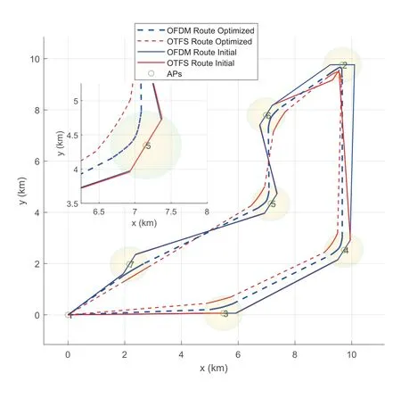
Figure 5. Different route of OTFS and OFDM in 2D perspective.
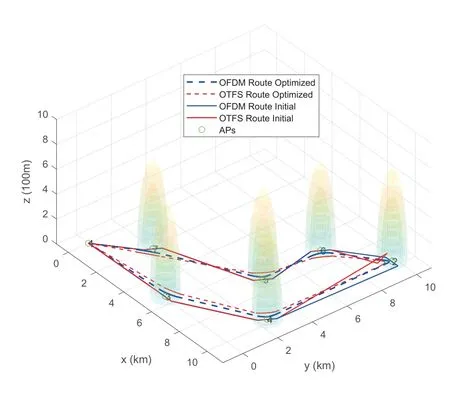
Figure 6. Different route of OTFS and OFDM in 3D perspective.
From Figure 5,we can see that the initial routes of OTFS and OFDM are almost identical,where the linesalong the tangent direction of OTFS-based UAV trajectory and OFDM-based UAV trajectory represent the velocity direction of them located atPin(i,s),theis the line between the UAV positionPin(i,s) and APi,indicating the signal direction when the UAV communicates with the AP,and the angle between the velocity direction and the signal direction isθi,s,which should be larger than Doppler angle limitationθ0.Furthermore,as shown in Figure 4,the OTFS-based UAV communication system has a lower SNR or a higher Doppler speed under the same BER threshold,which means the OTFSbased UAV system has a larger communication range and a smallerθ0.Thus,OTFS-based UAV systems have higher degrees of freedom to find better trajectory than OFDM-based UAV systems.
In summary,OTFS-based UAV systems can accomplish communication tasks over shorter distance than OFDM-based UAV systems,which means the performance of the OTFS-based UAV system is superior to that of OFDM system in terms of energy consumption under the same conditions.
V.CONCLUSION
In this paper,we have proposed OTFS-based UAV communication systems to combat severe Doppler effect caused by the high mobility of UAVs,where the performance of OTFS-based UAV communication was compared with the OFDM-based UAV communication.Then,the trajectory planning of UAVs was optimized to minimize the energy consumption under the constraints of BER and transmission rate,where the Doppler compensation is taken into account.Finally,simulation results showed that our proposed method provides better performance than the OFDM-based method.
ACKNOWLEDGMENT
This work was supported by the National Key Research and Development Program of China (Grant 2020YFB1804800),the National Natural Science Foundation of China (Grant U22B2008 and Grant 61922010),and the Beijing Natural Science Foundation(Grant JQ20019).
杂志排行
China Communications的其它文章
- Secrecy Transmission of NOMA-OTFS Based Multicast-Unicast Streaming
- Orthogonal Time Frequency Space Modulation in 6G Era
- Joint Multi-Domain Channel Estimation Based on Sparse Bayesian Learning for OTFS System
- BER Performance Analysis of OTFS Systems with Power Allocation
- OTFS-Based Efficient Handover Authentication Scheme with Privacy-Preserving for High Mobility Scenarios
- Channel Estimation for OTFS System over Doubly Spread Sparse Acoustic Channels
