Low PAPR Channel Estimation for OTFS with Scattered Superimposed Pilots
2023-02-02WeiLiuLiyiZouBaomingBaiTengSun
Wei Liu ,Liyi Zou ,Baoming Bai ,Teng Sun
1 State Key Labs of Integrated Service Networks,Xidian University,Xi’an 710071,China
2 The 54th Research Institute of CETC,Shijiazhuang Hebei 050081,China
Abstract: Orthogonal time frequency space (OTFS)modulation has been proven to be superior to traditional orthogonal frequency division multiplexing(OFDM) systems in high-speed communication scenarios.However,the existing channel estimation schemes may results in poor peak to average power ratio(PAPR)performance of OTFS system or low spectrum efficiency.Hence,in this paper,we propose a low PAPR channel estimation scheme with high spectrum efficiency.Specifically,we design a multiple scattered pilot pattern,where multiple low power pilot symbols are superimposed with data symbols in delay-Doppler domain.Furthermore,we propose the placement rules for pilot symbols,which can guarantee the low PAPR.Moreover,the data aided iterative channel estimation was invoked,where joint channel estimation is proposed by exploiting multiple independent received signals instead of only one received signal in the existing scheme,which can mitigate the interference imposed by data symbols for channel estimation.Simulation results shows that the proposed multiple scattered pilot aided channel estimation scheme can significantly reduce the PAPR while keeping the high spectrum efficiency.
Keywords: OTFS;channel estimation;superimposed pilots;PAPR;interference mitigation
I.INTRODUCTION
In recent years,with the popularity of high-speed mobile communication scenarios such as high-speed railway communication [1],unmanned aerial vehicle (UAV) communication [2] and low-earth-orbit(LEO) satellites [3,4],OFDM communication systems widely used at present face great challenges[5].The high Doppler frequency shift caused by high speed seriously damages the orthogonality of the OFDM system,so the performance is seriously degraded [5].As a promising technology,OTFS modulation technology was proposed in [6],which transmits data in delay-Doppler(DD)domain,and has been proved to have superior performance in high mobility communication scenarios[6].
For OTFS system,the research can be roughly classified into two categories,one is symbol detection[7-9],the other one is channel estimation[10-16].Channel estimation plays a critical role for the system performance,which has attracted intensive research interests.In[10],one channel estimation scheme based on pilot frame was proposed,which places pilot symbols within one whole OTFS frame.However,this scheme has low spectral efficiency,and is also unsuitable for the case of fast time-vary channel.In[11],a embedded pilot placement scheme was proposed,where only one pilot symbol is placed and protected by guard interval.This scheme is valid for fast time-varying channel.However,the guard interval results in low spectrum efficiency.In[12],a embedded pilot pattern was proposed,where multiple pilot symbols are placed within a specific area and sparse Bayesian learning algorithm was used to estimate channel.However,for large maximum doppler and maximum delay,the spectral efficiency of this scheme is low.In [13],a embedded pilot pattern without guard interval was proposed,which enhances the spectral efficiency,and the sparse Bayesian learning framework was adopted for channel estimation.In [14],a superimposed pilot pattern was proposed,where one pilot symbol was superimposed with one data symbol and an iterative channel estimation scheme was proposed.This scheme overcomes the drawback of low spectral efficiency of embedded pilot pattern.In [15],a mutiple superimposed pilot scheme was invoked,which requries that the delay and Doppler keep constant for several consecutive OTFS frames.For MIMO-OTFS systems,a channel estimation scheme was proposed in [17],while for massive MIMO systems,angle domain was invoked for channel estimation in[18].
Furthermore,for OTFS system,the peak to average power ratio(PAPR)performance has also been intensively investigated[19-22].However,the exsiting work is mainly for the PAPR performance analysis,where only data symbols are considered instead of the superimposed data symbol and pilot symbol.Moreover,the channel estimation scheme in [14] requires high pilot power,which may result in poor PAPR performance.
Against this background,in this paper,we investigate low PAPR channel estimation scheme with superimposed pilot symbol placement.The major contributions of this paper are summarized as follows:
• In order to reduce the PAPR,multiple scattered pilot symbols are invoked within one OTFS frame,where each pilot symbol is superimposed with a data symbol and has low transmission power.Furthermore,we design the rule for scattered pilot placement,which can provide guarantee the lower PAPR against the single pilot scheme[14].Moreover,joint channel estimation is designed by exploiting multiple received signals,which can mitigate the interference imposed by data symbols,hence,resulting in better channel estimation performance against the single pilot scheme[14],which further improves BER performance.
II.OTFS SYSTEM
2.1 System Mode
In the OTFS system,the data symbolsx[k,l] in the delay-Doppler (DD) domain where 0≤k ≤N -1,0≤l ≤M -1 are transformed into the data symbolsX[n,m]in the time-frequency domain through the inverse symplectic finite Fourier transform(ISFFT)[7],which is given by

where 0≤n ≤N -1,0≤m ≤M -1.The timefrequency domain signalX[n,m] is transformed to the time domain signals(t)by using Heisenberg transform[7],which is given by

wheregtx(t)is transmitting pulse carrier,Tis the duration of a symbol,Δfis subcarrier spacing.Then,the transmitter transmits the time domain signals(t)to the receiver.The time domain signalr(t)received by the receiver[7],which is given by

whereω(t)is noise with power spectral density(PSD)No.The channel in the DD domain can be expressed as[7]

wherePis the number of channel,hiis the channel gain of thei-th channel path.
The time-frequency domain signalY[n,m] is obtained by demodulation at the receiver.Finally,the time-frequency domain signalY[n,m] will be transformed into a signaly[k,l] in DD domain by using Symplectic Fourier Transform(SFFT)[7]

2.2 OTFS PAPR
The time domain signal duration mentioned in the previous section isNT,the discrete time domain signal can be obtained by sampling[23],which is given by

whereTSis sampling interval time,andu=0,1,...,NM -1.Letu=r+qMwherer=0,1,...,M -1 andq=0,1,...,N -1,and upon substituting(1)into(6),we have[23]
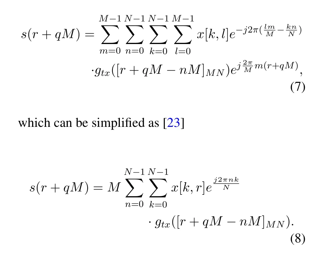
Consequently,the PAPR of OTFS systems can be expressed as[23]

III.LOW PAPR CHANNEL ESTIMATION FOR OTFS SYSTEM
3.1 Scattered Pilot Placement
For superimposed pilot pattern in [14],there is only one pilot used.The placement of pilot for channel estimation is shown in the following formula(10)

According to(10),max|s(r+qM)|2is affected by the pilot power.As only one pilot symbol is used,in order to have good channel estimation performance,high pilot symbol power may be required,which results in high PAPR.
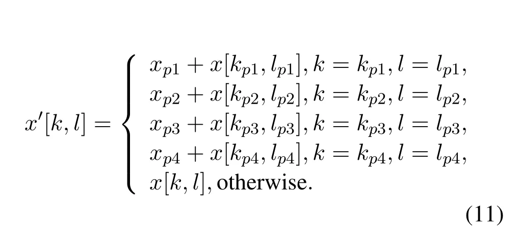
In order to reduce the PAPR,we propose a scattered multiple low power pilot placement scheme as shown in Figure 1.Multiple low power pilot symbols are placed at different positions within one OTFS frame.Specifically,the placement of pilot is given by
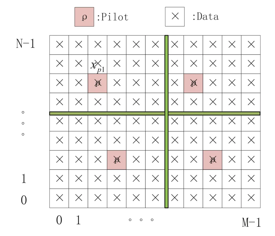
Figure 1. Schematic of multiple pilot placement.
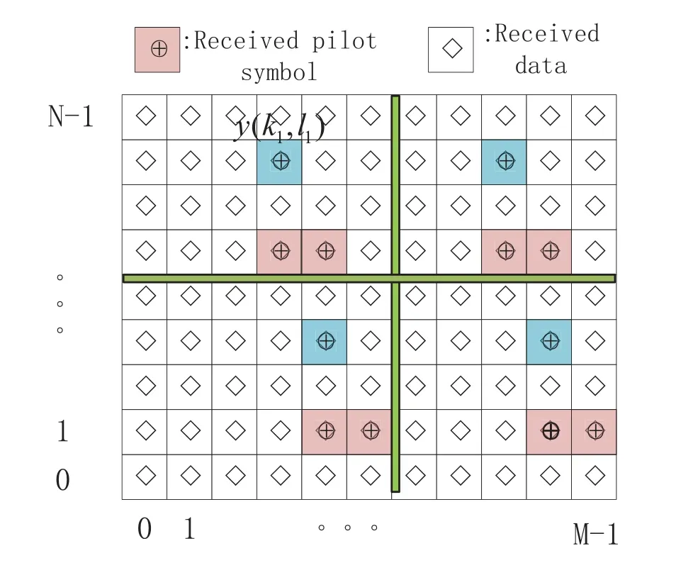
Figure 2. Schematic of joint channel estimation.
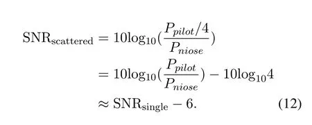
In this case,the total power of the pilot is scattered to four pilots.Denote SNRscatteredas SNR of a scattered pilot,SNRsingleis SNR of a single pilot [14],Ppilotas the total power of the single pilot[14],Pnioseas the power of noise,SNRscatteredis given by
There are two rules for positions of scattered pilots:
• They are independent with with each other.The separation between any two of them need to be larger than twice the maximum doppler or maximum delay [11].In this case,the received signal corresponding to each pilot is not interfered by other pilot symbols.
• They are in the different columns.
According to (8),s(r+qM) is dominated by theFurthermore,thecan be treated as Discrete Fourier transform of therth column of OTFS transmitted data frame[23].However,according to the additivity of the discrete Fourier transform[24],if two pilot symbols are placed in the same column,is increased,resulting in a larger max|s(r+qM)|2,which increases the PAPR.Hence,in order to reduce the PAPR,any two of the pilot symbols cannot be placed in one same column.
According to(11),the receiving symbol can be expressed as[14]

wherehw[k,l] is the effective channel in DD domain[14].
3.2 Multiple Pilot Aided Iterative Channel Estimation
In this section,we propose multiple pilot aided iterative channel estimation scheme,which adopts the main framework proposed in[14].However,there exist two main differences between our scheme and the scheme in [14].The first one is that as multiple distributed pilot symbols are placed instead of one single pilot in [14],the joint channel estimation by exploiting the multiple independent received signals can be used,which can mitigate the interference imposed by the data symbols.The other one is that as joint channel estimation is used,which means the lower power pilot symbol than that of the scheme in [14],which improves PAPR performance.
Specifically,the multiple pilot aided iterative channel estimation scheme takes the following steps:
Step 1:The received signal in the DD domain is divided into four independent areas according to the position of pilot as shown in Figure 2.
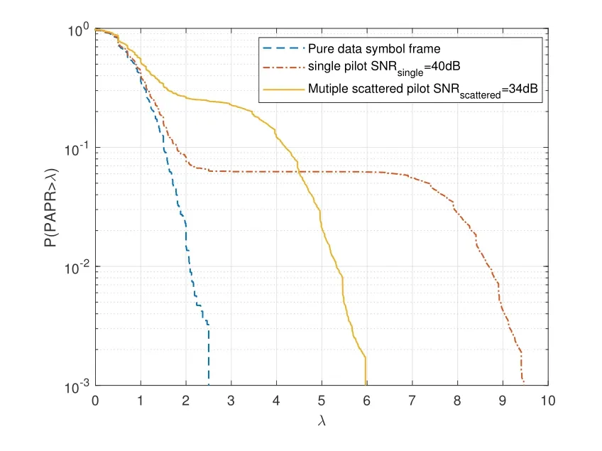
Figure 3. CCDF of PAPR for SNR=10dB.
For the upper left area,we need to identify which received signal contains the pilot symbol.Specifically,we can check the receivedy[k,l]in the area and comparing its modulus to given thresholdγ[14].If

which means the receivedy[k1,l1] contains one pilot symbol[14].Hence,we have[14]
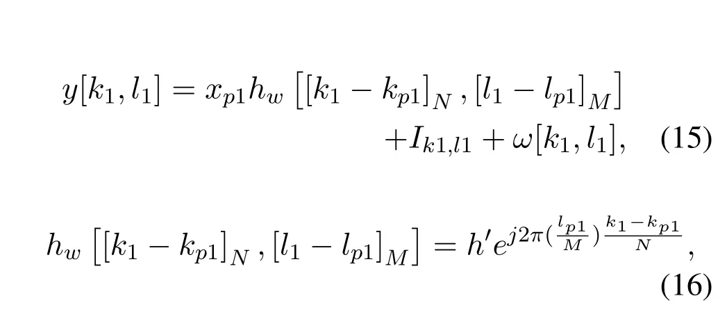
whereIk1,l1denotes the interference from data symbols,which is given by[14]
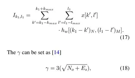
whereEs=E(|x[k,l]|2).
After step 1,we obtain the received signals contains pilot symbols.
Step 2:Determine the corresponding received signal for one of the channel paths.
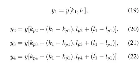
For the same channel path,denote the received signal contain the pilot symbol in theiindependent area asyi.According to (11),the pilot position is fixed.Once the received signaly[k1,l1]within the first area is found,we can directly determine the other three corresponding received signals in the other three areas respectively.Specifically,
Step 3:Phase restoration for the corresponding received signals.
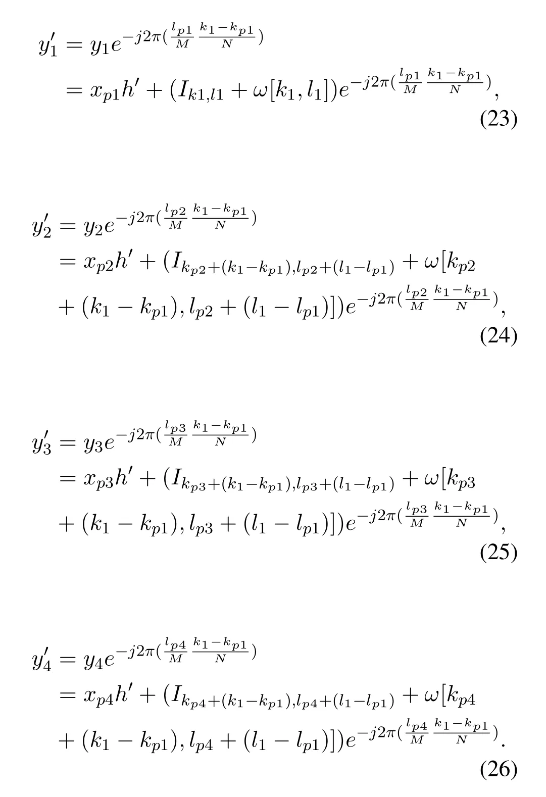
According to (16),for different received signals,there exist different phase rotation for the same channel path[7].Hence,in order to estimate the one channel path from (19)-(22),phase restoration is needed firstly.Denote the received signal after phase restoration asy′i,we have
Step 4:Joint channel estimation with interference mitigation.
According to(23)-(26),as four received signals correspond to one channel path is determined,we can use these four received signal to jointly estimate the channel.Denote the estimated channel path forh′as ︿h′,we have

whereωdenotes the noise andIdenotes the interference imposed by data symbols.Furthermore,

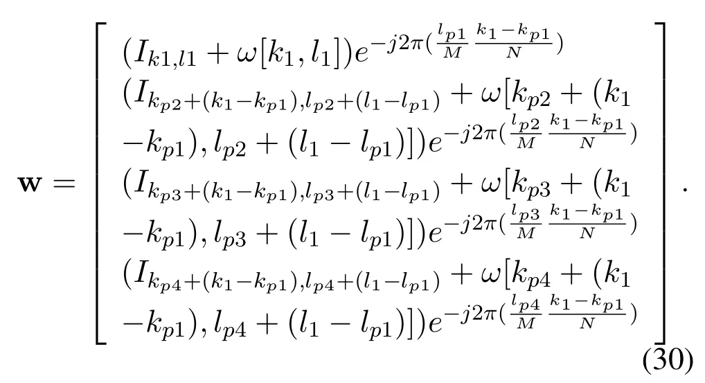
The channel estimation performance is determined by both noise and interference.Assuming that there areKpilots.For the noise,we have

which has the same distribution withωifor the single pilot case.
However,for the interference,we have

wherexijis the data symbol from the constellation.For the channel pathhi,only if{xij}are in the same direction,has the same effect ashixijfor the single pilot case.However,as thexijis independent and identically distributed,thexijmay cancel off with each other,hence the effect ofhiis mitigated.Furthermore,the largerK,the more interference may be mitigated.Hence,multiple pilots can improve the channel estimation performanace agaisnt the single pilot.
Step 5:Obtain the channel estimation for other channel paths[14].
Similarly,for the other channel paths,channel estimation can be performed following the Step 1 -Step 4 and the coarse channel estimation is completed.Denote the estimated channel path as,1≤w ≤P,wherewmay be less thanP,Pindicates the number of the total channel paths.The reason for that is some channel paths may not be detected.
Step 6:Data symbol detection based on estimated channel.
Based on the estimated channel,symbol detection can be performed.For example,by using the MP detector,the detected symbol[k,l]is given by[7]

where A is constellation set,Qis the cardinality of constellation set,y is a(NM×1)-dimensional vector[7].
Step 7:Interference cancellation for iterative channel estimation[14].
According to(15),the data symbols impose interference for pilot symbol.Hence,based on the estimated data symbols,the interference from data symbols can be cancelled for iterative channel estimation.Specifically,we have

Step 8:Iterative channel estimation.
According to(34),repeating from the Step 1,iterative channel estimation can be performed.The iterative process can be terminated when the performance gain by running more iterations is marginal[14].Note that,the threshold is updated at ther-th iteration as[14]

whereJrindicates the number of the estimated channel paths at ther-th iteration.
IV.SIMULATION RESULTS
In this section,we demonstrate the performance of the proposed multiple scattered pilot aided low PAPR channel estimation scheme for OTFS system.Furthermore,the single pilot based channel estimation scheme in[14]is adopted as the benchmark.Specifically,we set theN=16 andM=16 for one OTFS frame.Furthermore,there are 16 subcarriers and 16 time slots in time-frequency domain.Moreover,the central frequency of the carrier isfc=3GHz and the subcarrier spacing is Δf=15kHz,the delay spread is 4.7µs,which results inτmax=2.In addition,the maximum moving speed is 500Kmph,which results inνmax=2.Furthermore,Rayleigh fading channel is assumed,where the channel coefficienthifollows the distributionCN(0,1).One typical application scenario of OTFS is for UAV,where two-Ray or three-Ray chanenl model is normally used[25,26].Hence,we set the number of channel paths to beP=3.Moreover,the SNR for the data symbol is defined asFurthermore,we set SNRsingle=40dB for the channel estimation scheme in[14].According to(12),in order to keep the same total pilot power as that in [14],we set SNRscattered=34dB.Moreover,the MP detector is used for data symbol detection.
In the Figure 3,the complementary cumulative distribution function (CCDF) of the PAPR is plotted for our proposed scheme,the single pilot scheme,as well as the pure data symbol frame for SNR=10dB.It can be seen from Figure 3,the PAPR of pure data symbol frame falls below the 2.5 with the probability of 100%.Furthermore,for our scheme,the PAPR is increased due to superimposed pilot symbols and falls below the 6 with the probability of 100%.However,for the single pilot scheme,the distribution of PAPR mainly lies in two regions,for the below 2,and the other is between 7 and 9.5.The reason for that is some PAPR is not affected by the pilot symbol,hence it obeys the distribution of the pure data symbol frame,while for the PAPR affected by pilot symbols,it is increased significantly,and falls in the region between 7 and 9.5,which is higher than that of our proposed scheme.Hence,our proposed multiple pilot aided channel estimation scheme has better PAPR performance against the single pilot scheme in[14].
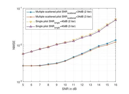
Figure 4.NMSE performance of channel estimation against SNR.
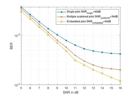
Figure 5. BER performance against SNR.
In Figure 4,normalized mean square error(NMSE)performance of channel estimation against SNR is plotted for both our proposed multiple scattered pilot scheme and single pilot scheme,where NMSE is defined asFrom Figure 4,we can see that for both second iteration and third iteration,our proposed scheme outperforms the single pilot scheme,which is due to the interference mitigation provided by our scheme.Furthermore,the NMSE performance of the third iteration is better than that of the second iteration,which is due to more interference is canceled.Moreover,the NMSE performance is getting worse with the increasing of SNR.The reason for that is higher data symbol power imposes severer interference on the pilot symbol in(15).
In the Figure 5,BER performance against SNR is plotted for our proposed multiple scattered pilot scheme,single pilot scheme and embedded pilot scheme [11].From Figure 5,we can see that embedded pilot scheme outperforms both our proposed multiple scattered pilot scheme and single pilot scheme.The reason for that is there is interference from data symbols on the pilot symbol with guard interval,which results in more accurate channel estimation.However,the embedded pilot scheme has lower spectrum efficiency.Furthermore,our proposed multiple scattered pilot scheme outperforms the single pilot scheme,which is due to our scheme can provide more accurate channel estimation than the single pilot scheme,as shown in Figure 4,which results better BER performance.Moreover,both our proposed multiple scattered pilot scheme and single pilot scheme has a higher spectrum than embedded pilot scheme.Specifically,the spectrum efficiency of embedded pilot scheme is[14]

whereNguardis the number of grids occupied by the guard interval,while the spectrum efficiency of both multiple scattered pilot scheme and single pilot scheme is[14]

Hence,11.1% improvement of spectrum efficiency can be achieved.
V.CONCLUSION
In this paper,we proposed multiple scattered superposition pilot aided channel estimation scheme,which improves the PAPR performance of OTFS system against the existing single pilot scheme.Moreover,this scheme has better channel estimation performance due to interference mitigation brought by multiple scattered pilot compared with the single pilot scheme.Furthermore,the proposed scheme can keep high spectrum efficiency.
ACKNOWLEDGEMENT
This work was supported by National Natural Science Foundation of China(No.61871452).
杂志排行
China Communications的其它文章
- Coordinated Planning Transmission Tasks in Heterogeneous Space Networks: A Semi-Distributed Approach
- Secrecy Rate Maximization for 6G Cognitive Satellite-UAV Networks
- Secure Transmission in Cognitive Radio Networks Using Full-Duplex Technique with Outdated CSI
- Computation Rate Maximization in Multi-User Cooperation-Assisted Wireless-Powered Mobile Edge Computing with OFDMA
- A Novel Multi-Granularity Flexible-Grid Switching Optical-Node Architecture
- Model-Free Adaptive Frequency Calibration for Voltage-Controlled Oscillators
