Investigations on lubrication characteristics of high-speed electric multiple unit gearbox by oil volume adjusting device
2023-01-16ShuaiSHAOKailinZHANGYuanYAOYiLIUJunGU
Shuai SHAO, Kai-lin ZHANG, Yuan YAO, Yi LIU, Jun GU
Research Article
Investigations on lubrication characteristics of high-speed electric multiple unit gearbox by oil volume adjusting device

1State Key Laboratory of Traction Power, Southwest Jiaotong University, Chengdu 610031, China2Suzhou shonCloud Engineering Software Co. Ltd., Suzhou 215100, China
In this paper, a numerical simulation model of the flow field in a gearbox with an oil volume adjusting device is established for the first time to study its influence on the lubrication characteristics of a high-speed electric multiple unit (EMU) gearbox. The moving particle semi-implicit (MPS) method is used to numerically simulate the internal flow field of the gearbox of the high-speed EMU under working conditions. The effects of the velocity of the high-speed EMU, the immersion depth, and the oil sump temperature on the power loss of the gears and the lubricant quantity of each bearing are studied and provide an effective tool for the quantitative evaluation of the lubrication characteristics of the gearbox. The lubrication characteristics of the gearbox under different working conditions are studied when the oil volume adjusting device is closed and opened. The results show that the oil volume adjusting device mainly changes the amount of lubricant stirred by the output gear by changing the flow rate of lubricant from the cavity pinion (Cavity P) to the cavity gear (Cavity G), and thus affects the power loss of gears and the lubricant quantity of each bearing.
High-speed electric multiple unit (EMU); Splash lubrication; Mesh-free moving particle semi-implicit (MPS) method; Bearing lubrication; Churning power loss; Oil volume adjusting device
1 Introduction
The gearbox is key equipment in the power transmission system of a high-speed electric multiple unit (EMU) and is one of its 10 supporting technologies. Three distinctive features of a high-speed EMU gearbox are high transmission power, high rotational speed, and high loading capacity requirement of the gears. These characteristics make it necessary for gears and bearings to be fully lubricated. The lubrication mode of a high-speed EMU gearbox is splash lubrication, that is, the output gear is immersed in a certain depth of lubricant and the gears and bearings are lubricated by lubricating oil splashed during the rotation of the gears. Good lubrication of the gears and bearings is essential for the stable operation of the gearbox.
Many studies on splash lubrication have been reported, among which experimental research is the most intuitive method. Leprince et al. (2012) used the single-gear churning test rig for the first time to quantitatively analyze the lubricant flow rate of gears under different gear parameters and rotational speeds. They combined the piecewise functions of the lubricant flow rate generated by a gear or one disk under different rotational speeds so as to provide an experimental reference for the quantitative study of the oil projected by gears rotating in an oil bath. Changenet and Velex (2008), Neurouth et al. (2017), and Boni et al. (2017) established the test rigs of a single gear, a gear pair, and a planetary gear pair, respectively. They studied the flow regimes and churning loss of the splash lubrication of gears with different structural parameters and established a series of gear churning loss calculation models. Neurouth et al. (2014) further evaluated the applicability of splash lubrication technology to high-speed gear pairs. However, the experimental research method has the disadvantages of poor repeatability, high cost, and limited operational conditions, so the method cannot be widely promoted and used.
With the development of computer technology and numerical simulation technology, the computational fluid dynamics (CFD) method can avoid the above limitations and make the analysis of gear splash lubrication characteristics by numerical simulation a reality. At present, there are five main numerical methods for modelling the splash lubrication of a gearbox. They are the finite volume method (FVM), the finite difference method (FDM), the finite element method (FEM), the meshless particle method (MPM), and the lattice Boltzmann method (LBM), of which FVM and MPM are those most commonly used. Liu et al. (2017) established a single-stage gearbox simulation model based on FVM and analyzed the influence of oil viscosity and circular speed on oil distribution and churning power loss by using an experimental-computational method. The results showed that the simulation results were in good agreement with the experimental results from a Gear Research Center (FZG) test rig. According to the numerical model established in the reference (Liu et al., 2017), Mastrone and Concli (2021) used grease rather than oil as the lubricant and analyzed the main fluxes in the gearbox with three different filling levels and higher tangential speeds. Hu et al. (2019) and Jiang et al. (2019) studied the splash lubrication characteristics of a more compact bevel gear transmission. Hu et al. (2019) mainly focused on the churning power loss generated by the gear transmission system, while Jiang et al. (2019) further studied the influence of an oil guide device and its geometric parameters on splash lubrication characteristics. In addition to splash lubrication, oil jet lubrication is often applied to the bevel gear transmission system to meet its more stringent lubrication requirements. Dai et al. (2019) proposed a novel numerical model to study the effect of nozzle layout parameters on the oil jet lubrication performance of bevel gears and gave a set of optimal nozzle arrangement parameters. Mastrone and Concli (2022) put forward a multi-domain division method to analyze the transmission efficiency and power loss of a two-stage speed reducer. The results showed that the power loss predicted by this method is in good agreement with the experimental results and it was considered that it could be extended to more complex multi-stage gear transmission systems. The above literature shows that the traditional FVM method can be used to study the oil flow behavior inside the gearbox, but it is necessary to simplify the meshing area and to combine it with advanced grid processing technology. The mesh processing technologies commonly used in the meshing area include the moving mesh method, the sliding mesh method, the immersed solid boundary method, and the overlapping mesh method. Among the methods, the moving mesh method has higher accuracy in predicting the flow field distribution and power loss (Li et al., 2022). The gearbox structure used in practical engineering is very complex, including a variety of oil paths and flow guide devices. Therefore, when studying a gearbox with complex structure or multi-stage transmission, FVM usually has the disadvantages of large pre-processing workload and low calculation efficiency.
The MPM is a version of the meshless method, which uses a series of a finite number of discrete points to describe the state of the system and to record its motion. Each particle can be associated with a discrete entity or can form a part of a continuous entity. Smoothed particle hydrodynamics (SPH) and moving particle semi-implicit (MPS) are two widely used MPMs based on Lagrange. Ji et al. (2018) applied a multi-phase SPH formula to investigate the multi-phase flow inside a gearbox and analyzed the aeration effect for the first time. Legrady et al. (2022) conducted similar research for an industrial gearbox. The results showed that the SPH can accurately predict the oil flow characteristics around the gear pair, but the predicted power loss is quite different from the experimental results, which is consistent with the findings of Liu et al. (2019). In contrast, the MPS can not only predict oil distribution well, but can also predict churning power loss well (Li et al., 2018; Guo et al., 2020). Deng et al. (2020a, 2020c) systematically studied the effects of rotational speed, oil immersion depth, oil viscosity, worm arrangement, and rotor shape on the lubrication performance of a worm drive with complex surface contact, by an experiment-simulation method. In MPS, the lubricant itself is discretized rather than the simulation space, which breaks away from the limitation of the grid and can effectively avoid the grid distortion caused by too complex a model or too small a meshing clearance at the meshing area. Therefore, the MPS is often used for gearboxes with complex structures or multi-stage transmissions and is of great significance in engineering applications. Deng et al. (2020b) as well as Xie et al. (2021) established high-precision CFD simulation models of different types of rail transit vehicle transmission systems and analyzed the effects of input speed, initial immersion depth, and lubricant viscosity on the lubrication characteristics of their gearboxes. As a key component in a gearbox, the lubrication state of bearings has attracted the attention of many researchers. However, in their research, only the churning power loss and oil distribution have been studied and no further studies have been conducted on the lubrication state of the bearings.
To ensure that the bearing is in a good lubrication state, many measures are adopted, such as setting an oil guide device on the inner wall of the box, installing an oil volume adjusting device at the bottom of the gearbox, and seasonally adjusting the amount of lubricant in the gearbox. Among these methods, installing an oil volume adjusting device at the bottom of the box is that most commonly used. Therefore, the gearbox model of a high-speed EMU is taken as the research object in this paper. The MPS is used to analyze the influence of different velocities, oil immersion depths, and oil temperatures on the oil distribution in the gearbox, the churning loss of a gear pair, and the lubricant volume of each bearing. By comparing the lubrication characteristics of the gearbox with the oil volume adjusting device in two different working states of closing and opening, the working mode of the oil volume adjusting device and its influence on the lubrication characteristics of the gearbox are studied.
This paper is structured as follows. The numerical method, MPS, used in this study is shown in Section 2, including its governing equations, particle interaction model, boundary conditions, and churning power losses. Section 3 presents the gearbox model and simulations, including a detailed description of a gearbox model of a high-speed EMU, numerical simulation conditions, and particle size verification. In Section 4, we apply the MPS method to the standard FZG test rig gearbox model to verify the accuracy and applicability of the current numerical model. Section 5 shows the numerical results of the gearbox under different working conditions when the oil volume adjusting device is closed and open, and discusses the influences of velocity, oil immersion depth, and oil sump temperature on the lubrication characteristics of the gearbox. The main conclusions drawn in this study are presented in Section 6.
Moreover, some unimportant but indispensable chapters are shown in Sections S1–S3 of the electronic supplementary materials (ESM) to enhance readability. Section S1 presents the concepts of kernel function and particle number density in MPS and shows the gradient function and Laplace operator of the particle used to solve the governing equation. Section S2 presents the free surface discrimination method and the wall boundary treatment strategy, which is very important for the convergence and stability of the MPS algorithm. Section S3 introduces the working process of the gearbox and the simplification measures of the 3D CFD simulation model.
2 Numerical method
2.1 Governing equations
The MPS is a meshless method, based on Lagrange particles, which focuses on tracking the change process of the kinematic and dynamic properties of particles. Each particle is interconnected through a kernel function. Since the MPS is completely described by Lagrange, the discrete convection term is not required and the numerical diffusion caused by the discrete convection term can be avoided. For an incompressible fluid, the continuity equation and Navier-Stokes equation can be written as follows:
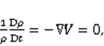

where D/Dis the derivative of matter,is the fluid density,is the pressure,is the velocity vector,is the kinematic viscosity coefficient of the fluid, andis the mass force.
2.2 Churning power losses
In MPS, the fluid force is applied to the gear surface by an interpolation method, and the product of the reaction force on the gear surface and the moment arm is the churning resistance torque. The churning resistance torqueof a gear can be divided into gear surface pressure, fluid viscous force, and turbulent shear stress. The pressure gradient operator used to calculate the gear surface is shown as:
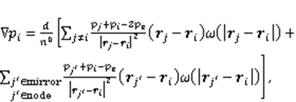
wherepis the pressure of particle,is the spatial dimension of the problem,0is the initial particle density constant,eis the ambient pressure,is the position vector of particle, andis the kernel function.
The product of the viscosity coefficient of the lubricant and the Laplace velocity term is taken as the fluid viscosity force:
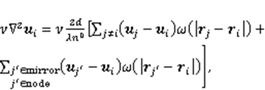
whereis the velocity vector of particle, andis the correction factor.
The turbulent shear stress on the gear surface is obtained by the turbulent mixing length model (Hutter and Wang, 2016):

whereis the turbulent shear stress,is the mixing length,is the mean velocity field, andis the distance to the wall.
Fig. 1 Exploded view of high-speed EMU gearbox. GW represents the outgear wheel side; GM represents the outgear motor side; PW represents the ingear wheel side; PM represents the ingear motor side
Then the churning power losses of the input gear and the output gear can be calculated by their own churning resistance torque and angular velocity, and the sum of the two is taken as the churning power loss of the gear pair:
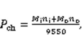
whereis the churning resistance torque of the gear, andis the rotational speed. Subscripts 'i' and 'o' represent the input gear and the output gear, respectively.
3 Model and simulation conditions
3.1 Gearbox model of high-speed EMU
The gearbox model of the high-speed EMU studied in this paper is a single-stage parallel shaft helical gear transmission, which uses splash lubrication. The specific components are shown in Fig. 1. The output gear is the power source of the splash, and the input gear and the bearings are the parts that need to be lubricated. Table 1 shows the parameters of the gear pair and bearings of the gearbox. The input shaft is supported by two tapered roller bearings NSK-SHA/R70, and the output shaft is supported by two tapered roller bearings NSK-SHA/R205.
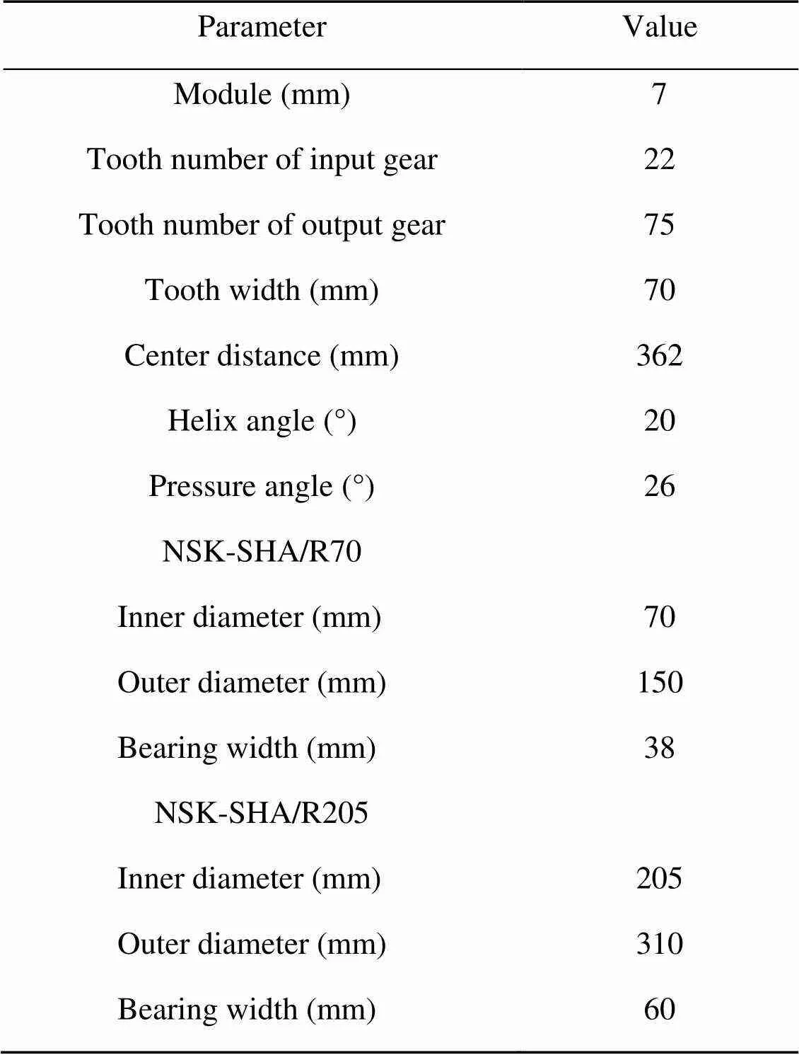
Table 1 Parameters of gear pair and bearings of gearbox
The oil volume adjusting device consists of the oil volume adjusting device frame, moving shaft, shape memory alloy spring, reel, constant-force scroll spring, and rubber plug (Fig. 2). One end of the constant-force scroll spring is fixed on the reel and the other end is fixed to the moving shaft. The shape memory alloy spring itself has thermal sensitivity, and its stiffness can change with the change of its body temperature. When the temperature of the lubricant is relatively low, the stiffness of the memory alloy spring is small, and the spring force generated by the shape memory alloy spring is less than the force of the constant-force spring. The oil volume adjusting device is opened, and the cavity pinion (Cavity P) and the cavity gear (Cavity G) are connected through the cavity connecting hole. When the moving shaft extends, the rubber ring butts the stiffener of the box, the oil volume adjusting device is closed, and the two oil cavities can only be connected through the flow regulating hole, and the flow rate of lubricant from the Cavity P to the Cavity G is reduced, so as to realize the regulation of lubricant quantity.
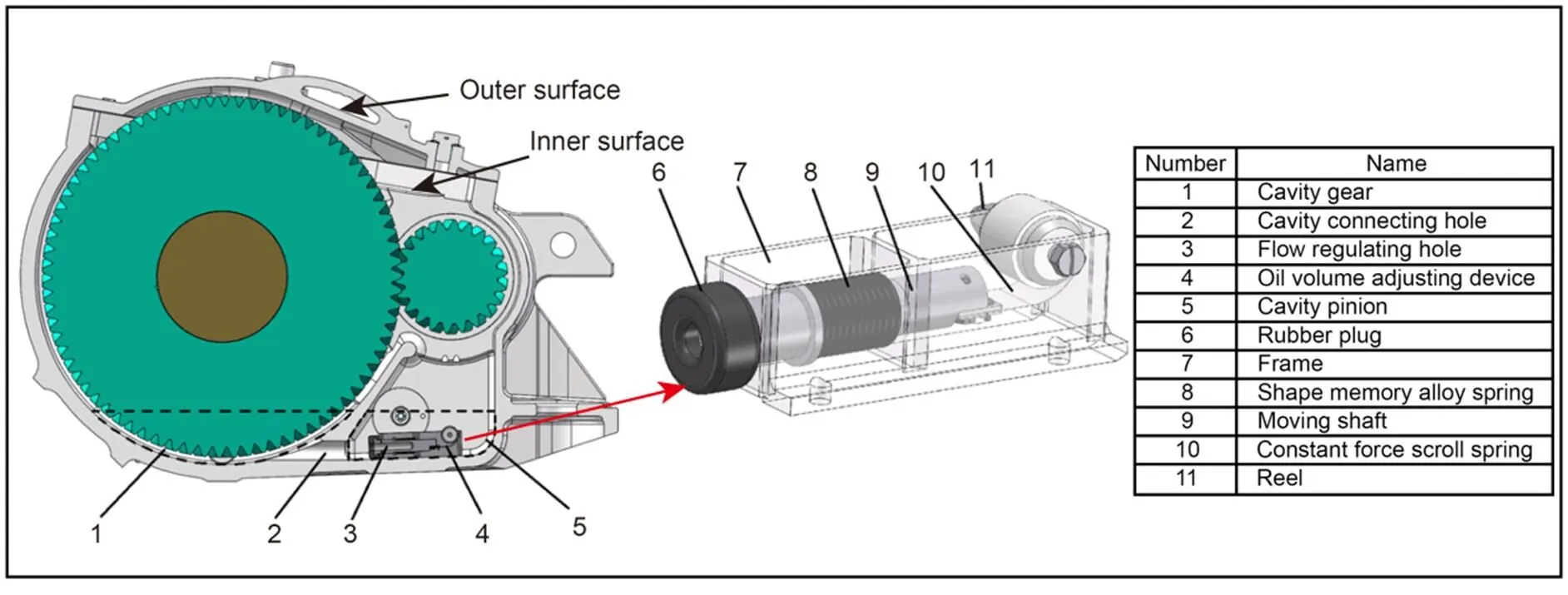
Fig. 2 Installation position and structure diagram of the oil volume adjusting device
3.2 Numerical simulation conditions
The simplified gearbox model of a high-speed EMU is imported into commercial CFD simulation software shonDy 2.3 (Guo et al., 2020), and the amount of lubricant is set according to the liquid level indication on the oil level gauge. When the immersion depth of output gear is three times the tooth height (3.0), it corresponds to the oil position indicated by the middle scribed line of the oil level gauge. To further study the influence of different lubricant amounts on the lubrication characteristics of the gearbox, four different immersion depths were set up, and particles with a radius of 1 mm were granulated in shonDy, as shown in Fig. 3. The lubricant particles after granulation are arranged in an orthogonal way. The numbers of particles under different oil amounts are shown in Table 2. The surface of each component in the gearbox is defined as a polygonal wall.
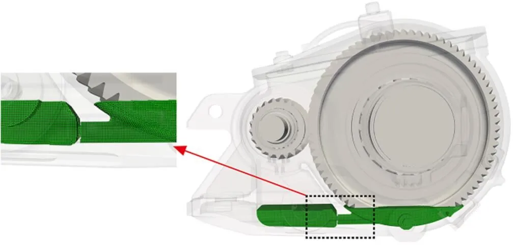
Fig. 3 Schematic diagram of lubricant particle model
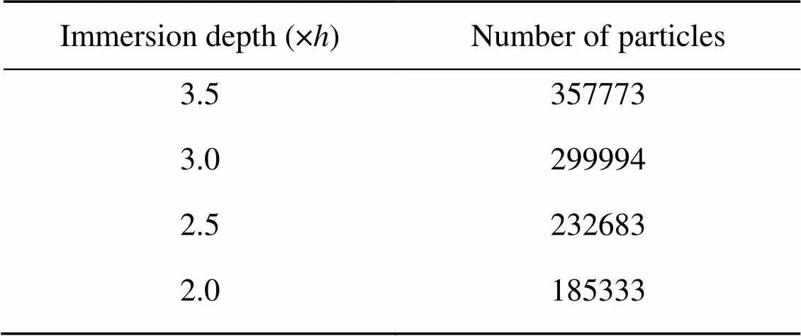
Table 2 Numbers of particles under different immersion depths
The motion parameters of the gears and bearings and the physical properties of the lubricant are defined in shonDy, and the internal flow field of the gearbox and the instantaneous distribution of the lubricant are simulated. Bearings are important parts of a gearbox, and are lubricated in open passive lubrication, mainly relying on the lubricant splash effect to achieve lubrication. To analyze the lubrication characteristics of a gearbox more accurately, the splashed lubricant volume of the bearing must be considered. We assume that the rotation of the bearing roller is ignored and only the revolution of the roller is considered. The amount of lubricant involved in the lubrication of each bearing is monitored by an annular sample, as shown in Fig. 4. By counting the number of lubricant particles of the annular sample, the product of the number of particles and the volume of individual particle is taken as the lubricant volume in the annular sample. The change rate of lubricant volume in an annular sample can be taken as the volume flow rate of lubricating oil of each bearing.

Fig. 4 Annular monitoring sample window on bearing
The gearbox uses a high-speed, heavy-duty, and low-temperature resistant lubricant Emgard RW-A 75W-90, which can meet the operating conditions of a high-speed EMU. Considering the influence of temperature on the physical properties of lubricating oil, referring to the physical properties of lubricating oil at 40 and 100 ℃, and according to the viscosity temperature relationship Eq. (7) given in the standard AGMA 925 A03 (AGMA, 2003), the viscosity and density corresponding to different oil temperatures are obtained, as shown in Table 3. In this study, density and viscosity were analyzed as important indicators of lubricant physical properties, and the effects of other additives (extreme pressure anti-wear agent, antifoaming agent, metal deactivator, etc.) on physical properties were not discussed.
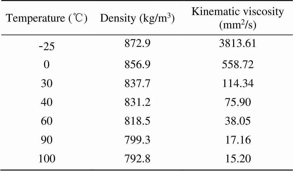
Table 3 Measured data of the experiments in five states
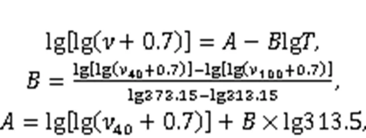
whereis the absolute temperature, K;andare constants;40and100are the kinematic viscosities of oil at 40 and 100 ℃, respectively.
The surface tension coefficient of the lubricant is set to 0.02 and the wall contact angle is set to 20°. The effect of gravity on the lubricant is set at 9.8 m/s2. Due to the complex flow law of lubricant in the gearbox, the turbulence model and wall sticking model are activated.
A suitable time step is necessary for accurate and efficient numerical simulation. An overlarge time step will usually lead to divergent solutions but too small a time step will make the calculation time too long and cause unnecessary waste. A suitable time step Δis estimated by:


To accurately analyze the influence of the oil volume adjusting device on the lubrication characteristics of the high-speed EMU gearbox, numerical simulation is carried out under 15 working conditions of different velocities, oil immersion depths, and oil sump temperatures. The simulation time of each working condition is set to 2.5 s. To reduce the impact of instantaneous start shock on the simulation results, 0–1.0 s is set to the gradual acceleration stage, and 1.0–2.5 s is set to the stable operation stage. The simulation calculation conditions are shown in Table 4. GK01–GK04 are used to study the influence of different oil immersion depths on the lubrication characteristics of the gearbox, GK05–GK11 are used to study the influence of different velocities on the lubrication characteristics of the gearbox, and GK12–GK15 are used to study the influence of different lubricant temperatures on the lubrication characteristics of the gearbox. To further analyze the influence of the oil volume adjusting device on the lubrication characteristics of the gearbox, 'O' and 'C' are used to represent the opening and closing of the oil regulating device, respectively. For example, GK01-O represents the simulation condition with the opened oil volume adjusting device, and GK01-C represents it with the closed oil volume adjusting device. All simulations are carried out on the Dell precision T7920 workstation (CPU: Intel Xeon Gold 6258R×2, RAM: 128 GB, graphics card: NVIDIA RTX A4000).
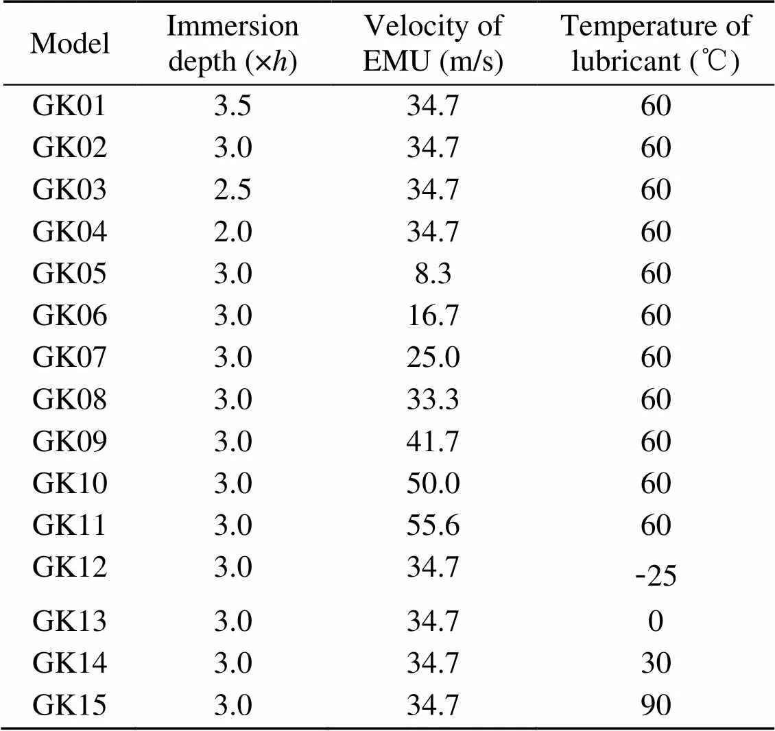
Table 4 Simulation conditions
4 Experimental verification
To verify the applicability and accuracy of the numerical model, the MPS is applied to the standard FZG test rig gearbox model. The internal dimension of the gearbox used in the simulation model is 274 mm×56 mm×175 mm. The gear pair parameters and the physical properties of lubricating oil are shown in Tables 5 and 6. For comparison with the experimental data, the result in reference (Liu et al., 2017) will be used.
According to Liu et al. (2017), the oil fill level is set to 36.7 mm below the shaft centerline, the rotation speed of the wheel is set to 407 r/min (corresponding to a circumferential speedtof 2.3 m/s), the acceleration time of the gear pair is 1.5 s, and the viscosity of the oil is set to 90 mm2/s. The oil is discretized by particles with a radius of 1 mm, and the oil distribution in the gearbox is numerically simulated. Then the oil distributions at start-up after the pinion rotates 50° and 100° are illustrated in Fig. 5. By adjusting the oil fill level and the viscosity of oil, the churning loss torque is numerically simulated, and the results are shown in Fig. 6.
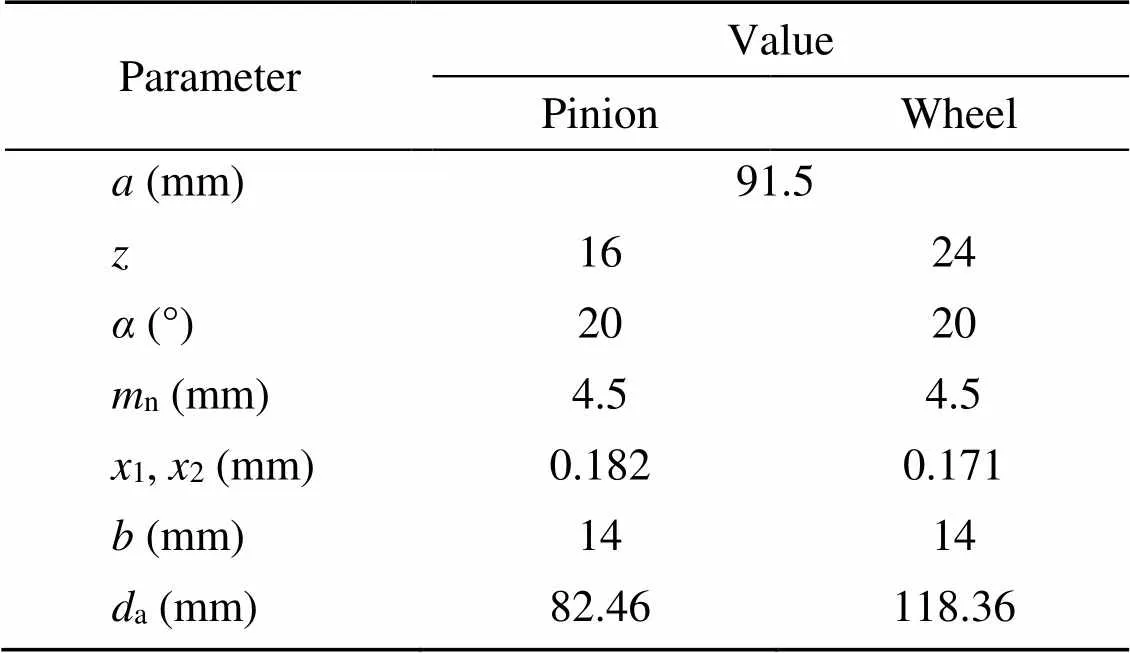
Table 5 Parameters of type C gear pair
is the center distance;is the number of teeth;is the pressure angle;nis the normal module;1is the addendum modification coefficient of pinion;2is the addendum modification coefficient of wheel;is the face width;ais the tip diameter

Table 6 Properties of lubricating oil
15represents the density at 15 ℃
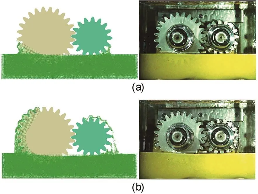
Fig. 5 Comparison of oil distributions at start-up after the pinion rotates 50° and 100°: (a) vt=2.3 m/s after 50°; (b) vt=2.3 m/s after 100°
It can be seen from Fig. 5 that the oil distributions obtained by numerical simulation are in good agreement with the experimental results from the FZG test rig. Although there are still some differences, the splash effect of gears on oil can be well simulated. The results of churning loss torque in Fig. 6 show that both simulation and experimental data indicate that the churning loss torque increases with the increase of rotating speed. For a pitch line velocity of 8.3 m/s, there is a certain error between MPS simulation data and experimental data. That error is mainly because the physical properties of lubricating oil in the simulation process are slightly different from those in the experiment. Liu et al. (2017) did not give the specific values corresponding to the temperature of oil at 60 and 90 ℃. In addition, it is also possible because of the influence on the resolution of the numerical results. If smaller particles are used to discretize the oil, more consistent numerical results will be obtained, but this will bring higher computational costs. By comparing the simulation results with the experimental results, it can be considered that the MPS well predicts the oil distribution in the gearbox and the churning power loss.

Fig. 6 Comparison of churning loss for constant temperature: (a) oil level=21.6 mm below center, T=60 ℃; (b) oil level=20 mm below center, T=90 ℃
5 Results and discussion
As a key component of the gearbox of an EMU, the lubrication state of the bearings is closely related to its working reliability. The inner surface of the gearbox in this study is smooth and flat. Only the oil guide plate is set below the gear mesh area, without complex structures such as an oil collecting groove and oil baffle. The four bearings in the gearbox are all lubricated with open passive lubrication. The lubricant involved in bearings consists of two parts: one is the lubricant splashed from the gear pair and the other is the lubricant flowing down along the inner surface of the box.
To further analyze the influence of the oil volume adjusting device on the lubrication characteristics of the gearbox, the motion morphology and distribution of lubricant particles under the two conditions of the opening and closing of the device are discussed for each working condition in Table 4. In this section, according to the simulation results of GK02-O and GK02-C, the influence of the oil volume adjusting device on the flow field characteristics of the gearbox is analyzed and the influence of different working states of the device on the power loss and lubrication states of gears and bearings is discussed in detail. Then, the influence of the oil volume adjusting device on the lubrication characteristics of an EMU gearbox under different velocities, oil immersion depths, and oil temperatures is further studied
5.1 Analysis of flow field characteristics in the gearbox
It can be seen from Figs. 7 and 8 that the lubricant at the bottom of the output gear is stirred to the top of the box and the bearings and gears in the gearbox are lubricated. Limited by the box structure, most of the lubricant particles stirred by the output gear will reach the input shaft and reach Cavity P under gravity. Due to the existence of an oil guide plate in the box, more lubricant is accumulated in Cavity P and this lubricant can only flow to Cavity G through the cavity connecting hole to participate in lubrication.
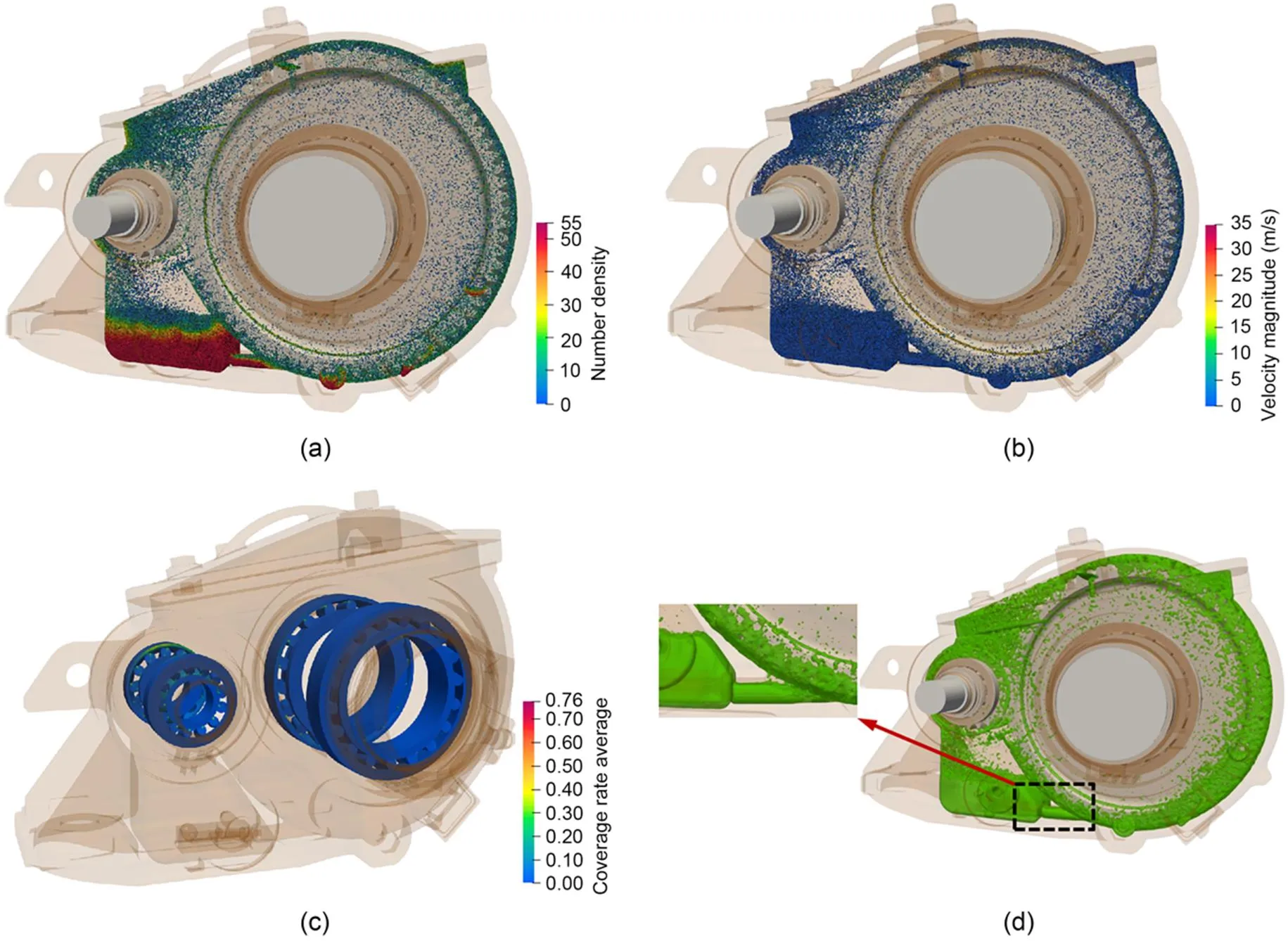
Fig. 7 Flow field characteristics of gearbox under GK02-C: (a) distribution of particle number density; (b) velocity field distribution; (c) bearing coverage rate average; (d) lubricant distribution
When the oil volume adjusting device is closed, the flow area between Cavity P and Cavity G changes from a cavity connecting hole to a flow regulating hole, which will significantly reduce the lubricant mass flow rate from Cavity P to Cavity G, as shown in Figs. 7d and 8d. Due to the reduction of lubricant from Cavity P to Cavity G, the lubricant stirred by the output gear is reduced, which will reduce the lubricant volume of each bearing.
It can be seen from Fig. 9a that when the oil volume adjusting device is closed, the lubricant volume of all bearings in the gearbox is reduced and the bearings installed on the input shaft are reduced the most. This is because closing the oil volume adjusting device will significantly reduce the lubricant stirred by the output gear and thus the volume of lubricant entering the bearing will be reduced. Most of the lubricant particles stirred by the output gear reach the top of the box and they will be splashed to the gears and bearings to participate in lubrication under the limitation of the box and the inertia of the lubricant particles. The decrease of the amount of the lubricant stirred will have a relatively significant influence on the lubricant volume of bearings installed on the input shaft. Due to the decrease of the amount of the agitated lubricant, the power loss of each component in the gearbox will be reduced accordingly, as shown in Fig. 9b. The churning power loss of the output gear is the most significant reduction, about 50% of the open state.
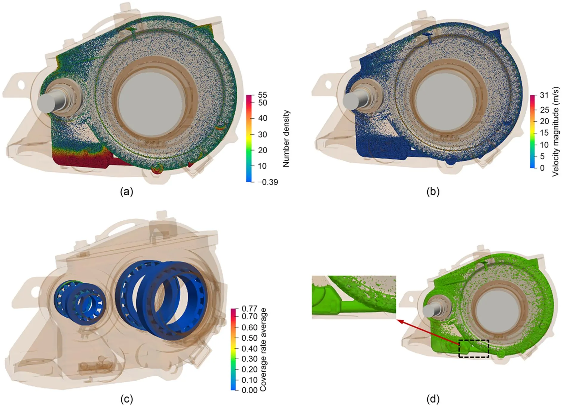
Fig. 8 Flow field characteristics of gearbox under GK02-O: (a) distribution of particle number density; (b) velocity field distribution; (c) bearing coverage rate average; (d) lubricant distribution
5.2 Influence of velocities
As can be seen from Fig. 10, the power loss of gears in the gearbox and the volume flow rate of each bearing increase with the increase of the velocity of the high-speed EMU. The variation law of power loss is consistent with that shown by Otto's experimental results (Otto, 2009). This is because, with the increase of the velocity of the high-speed EMU, the more lubricant stirred by the output gear, the greater the churning loss of the output gear. At the same time, if more lubricant is stirred up, the amount of lubricant around the gear pair and the mesh area will increase, resulting in an increase of wind resistance loss and mesh power loss of the gear pair. The more lubricant stirred by the output gear will not only increase the lubricant concentration in the gearbox, but also make more lubricant particles reach the surrounding area of the input gear and increase the volume flow rate for each bearing.
When the oil volume adjusting device is closed, the lubricant flow rate flowing from Cavity P to Cavity G will be reduced, making more lubricant accumulate in Cavity P, which will greatly reduce the volume of lubricant stirred by the output gear. The reduction of the volume of lubricant stirred by the output gear will reduce the power loss of the gear pair and the volume flow rate for all bearings. Due to the limitation of box and the lubricant distribution, the bearings installed on the input shaft are more sensitive to the working state of the oil volume adjusting device. After time-domain statistics of the lubricant coverage on the bearing at each moment, the maximum value is taken as the coverage rate maximum. The coverage rate maximum can be used to evaluate the bearing lubrication state, which reflects the same variation law, as shown in Fig. 11.
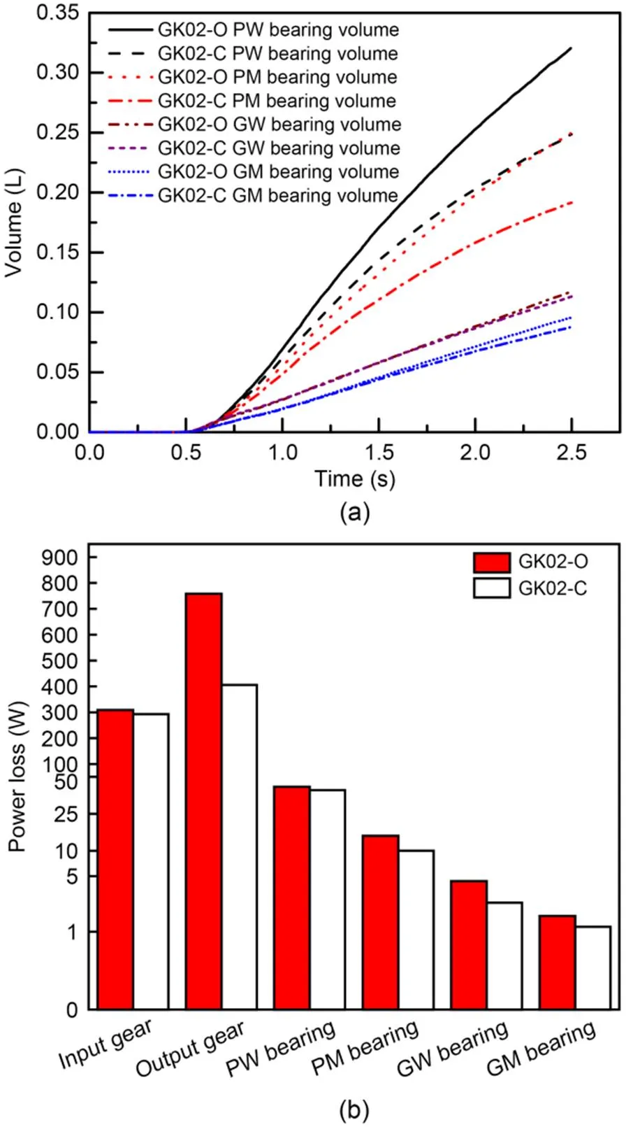
Fig. 9 Comparison of lubrication characteristics under GK02: (a) lubricant volume of bearings; (b) power loss of gears

Fig. 10 Comparison of lubrication characteristics with different velocities: (a) volume flow rate of each bearing; (b) power loss of gear pair
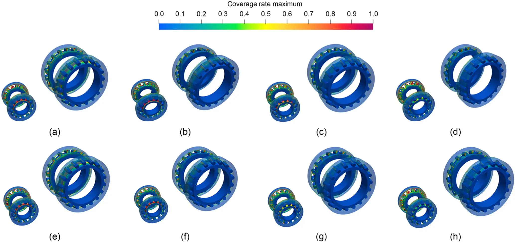
Fig. 11 Time-domain average of coverage rate maximum of bearing: (a) GK05-O; (b) GK07-O; (c) GK09-O; (d) GK11-O; (e) GK05-C; (f) GK07-C; (g) GK09-C; (h) GK11-C
5.3 Influence of oil immersion depths
As shown in Fig. 12, with the increase of the oil immersion depth, the power loss of the gear pair and the volume flow rate of each bearing will increase. This is because, with the increase of oil immersion depth, more lubricant will be stirred, which will increase the lubricant concentration in the gearbox and increase both the lubricant volume directly splashed to the bearings and the lubricant volume flowing into the bearings along the surfaces of the boxes. The increase of the amount of stirred lubricant will increase the churning loss of the output gear and the lubricant volume splashed around the input gear. Affected by the rotation of the gear pair, the lubricant entering the gear meshing area will also increase, which increases the mesh loss. Eventually, the power loss of the gear pair will be increased. Closing the oil volume adjusting device will reduce the lubricant amount stirred by the output gear, thereby reducing the volume flow rate of each bearing and the power loss of the gear pair.
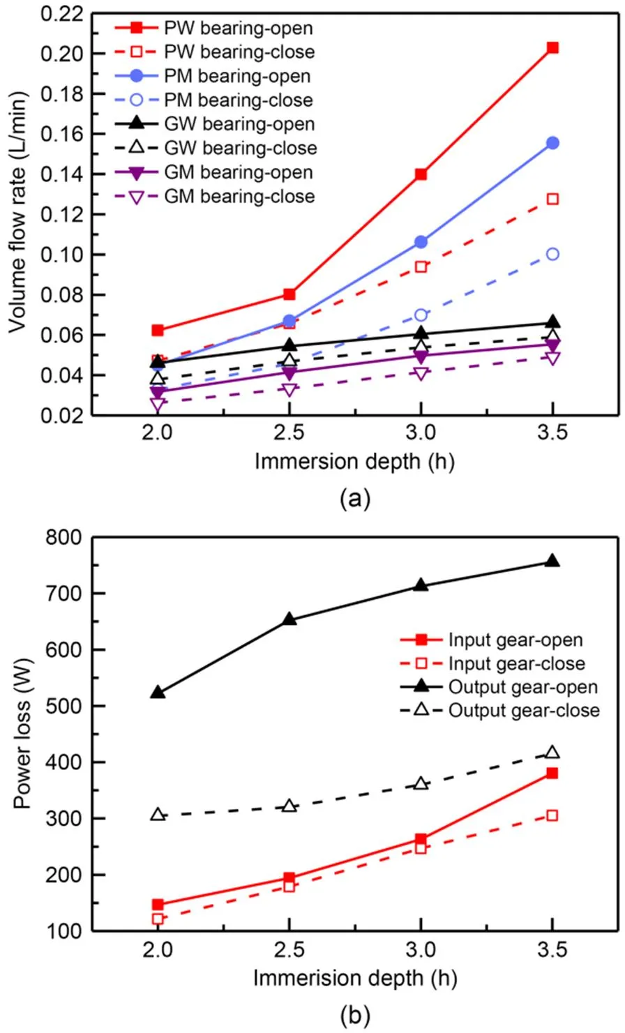
Fig. 12 Comparison of lubrication characteristics with different oil immersion depths: (a) volume flow rate of each bearing; (b) power loss of gear pair
5.4 Influence of oil sump temperatures
The oil sump temperature will affect the viscosity and density of lubricant, and the viscosity is more sensitive. It can be seen from Fig. 13 that the volume of lubricant of each bearing and the power loss of the gear pair increase with the increase in oil sump temperature. When the oil sump temperature exceeds 60 ℃, the upward trend slows down and tends to be stable. According to the viscosity temperature characteristic curve of the lubricating oil given by the standard AGMA 925 A03 (AGMA, 2003), from a low lub ricant temperature, the viscosity decreases sharply as its temperature increases. Then, as the temperature continues to rise, the rate of change of viscosity lessens. The low viscosity of the lubricant will enhance its fluidity, and the flow rate of the lubricant flowing from Cavity P to Cavity G will increase. More lubricant will be stirred by the output gear, increasing the power loss of the gear pair, and more lubricant will be thrown into the bearings to participate in lubrication
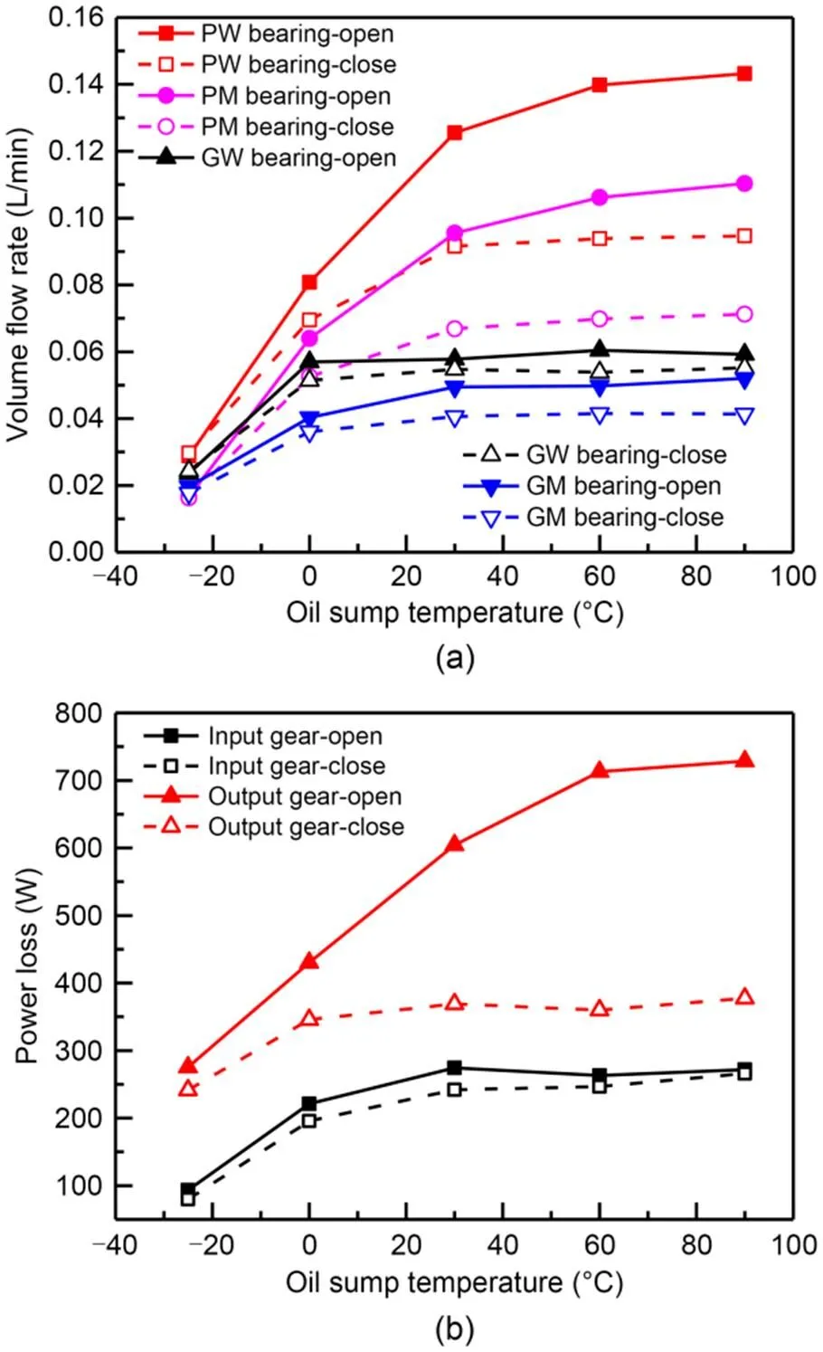
Fig. 13 Comparison of lubrication characteristics with different oil sump temperatures: (a) volume flow rate of each bearing; (b) power loss of gear pair
Oil sump temperature, as an important factor affecting the stiffness of the memory alloy spring, controls the working state of the oil volume adjusting device by cooperating with the constant-force scroll spring. It can be seen from Fig. 13 that the flow rate of lubricant flowing from Cavity P to Cavity G will be reduced by shutting down the oil volume adjusting device, which will greatly reduce the power loss of the gear pair and the lubricant volume of each bearing. The influences on the power loss of the output gear and the lubricant volume of the bearings installed on the input shaft are the most obvious effects.
6 Conclusions
In this paper, a numerical simulation model of the flow field in the gearbox of a high-speed EMU with an oil volume adjusting device is established and used to analyze the lubrication characteristics of the gearbox. The CFD simulation results reveal the influences of the oil volume adjusting device on the power loss of the gears and the lubricant quantity of each bearing under the working conditions of different velocities of the high-speed EMU, oil immersion depths, and lubricating oil temperatures. The following conclusions were reached:
1. By analyzing the lubricant distribution and velocity field in the gearbox of a high-speed EMU under different working conditions, it is shown that the MPS method has great advantages in analyzing the splash lubrication characteristics of a complex gearbox and in providing a theoretical basis for analyzing the lubrication characteristics of complex models.
2. By establishing a cylindrical inspection surface on the bearing, the lubricant quantity of each bearing under different working conditions is obtained. Combined with the power loss of gears, the lubricant quantity of each bearing, and the time-domain average of lubricant coverage rate, it provides an effective tool for quantitatively evaluating the lubrication characteristics of the gearbox.
3. The power loss of gears and the volume flow rate of lubricant of each bearing under various working conditions are analyzed. The results show that the power loss of gears and the volume flow rate of lubricant of each bearing are positively correlated with the velocity of the EMU, the immersion depth, and the oil sump temperature. The velocity has the greatest influence on the power loss of gears, and the higher the velocity, the more obvious the trend of power loss increases. The volume flow rate of lubricant of each bearing is most sensitive to the immersion depth. The deeper the immersion depth of output gear, the more obvious the growth trend of the volume flow rate of oil supply to each bearing.
4. By comparing and analyzing the influence of the two working states of the oil volume adjusting device on the lubrication characteristics of the gearbox, it is known that closing the oil volume adjusting device will reduce the flow rate of the lubricant from Cavity P to Cavity G. It mainly reduces the power loss of gears and the lubricant volume flow rate of each bearing by reducing the amount of lubricant stir red by the output gear.
Acknowledgments
This work is supported by the Natural Science Foundation of Sichuan Province, China (Nos. 2022NSFSC0034 and 2022NSFSC1901), the National Railway Group Science and Technology Program (No. N2021J028), the Independent Research and Development Projects of State Key Laboratory of Heavy Duty AC Drive Electric Locomotive Systems Integration (No. R111720H01385), and the Independent Research and Development Projects of State Key Laboratory of Traction Power (No. 2022TPL-T02), China.
Author contributions
Shuai SHAO and Yuan YAO designed the research. Shuai SHAO and Yi LIU processed the corresponding data. Shuai SHAO wrote the first draft of the manuscript. Kai-lin ZHANG helped to organize the manuscript. Jun GU contributed to the simulation technology of the study. Shuai SHAO, Yuan YAO, and Kai-lin ZHANG revised and edited the final version.
Conflict of interest
Shuai SHAO, Kai-lin ZHANG, Yuan YAO, Yi LIU, and Jun GU declare that they have no conflict of interest.
Electronic supplementary materials
Sections S1–S3
AGMA (American Gear Manufacturers Association), 2003. Effect of Lubrication on Gear Surface Distress, AGMA 925 A03. AGMA, USA.
Boni JB, Neurouth A, Changenet C, et al., 2017. Experimental investigations on churning power losses generated in a pla netary gear set. Journal of Advanced Mechanical Design, Systems, and Manufacturing, 11(6):JAMDSM0079. https://doi.org/10.1299/jamdsm.2017jamdsm0079
Changenet C, Velex P, 2008. Housing influence on churning losses in geared transmissions. Journal of Mechanical Design, 130(6):062603. https://doi.org/10.1115/1.2900714
Dai Y, Ma FY, Zhu X, et al., 2019. Evaluation and optimization of the oil jet lubrication performance for orthogonal face gear drive: modelling, simulation and experimental validation. Energies, 12(10):1935. https://doi.org/10.3390/en12101935
de Moura CA, Kubrusly CS, 2013. The Courant-Friedrichs-Lewy (CFL) Condition: 80 Years After Its Discovery. Birkhauser, Boston, USA, p.144-146. https://doi.org/10.1007/978-0-8176-8394-8
Deng XQ, Wang SS, Hammi Y, et al., 2020a. A combined experimental and computational study of lubrication mechanism of high precision reducer adopting a worm gear drive with complicated space surface contact. Tribology International, 146:106261. https://doi.org/10.1016/j.triboint.2020.106261
Deng XQ, Wang SS, Wang SK, et al., 2020b. Lubrication mechanism in gearbox of high-speed railway trains. Journal of Advanced Mechanical Design, Systems, and Manufacturing, 14(4):JAMDSM0054. https://doi.org/10.1299/jamdsm.2020jamdsm0054
Deng XQ, Wang SS, Qian LM, et al., 2020c. Simulation and experimental study of influences of shape of roller on the lubrication performance of precision speed reducer. Engineering Applications of Computational Fluid Mechanics, 14(1):1156-1172. https://doi.org/10.1080/19942060.2020.1810127
Guo D, Chen FC, Liu J, et al., 2020. Numerical modeling of churning power loss of gear system based on moving particle method. Tribology Transactions, 63(1):182-193. https://doi.org/10.1080/10402004.2019.1682212
Hu XZ, Jiang YY, Luo C, et al., 2019. Churning power losses of a gearbox with spiral bevel geared transmission. Tribology International, 129:398-406. https://doi.org/10.1016/j.triboint.2018.08.041
Hutter K, Wang YQ, 2016. Turbulent mixing length models and their applications to elementary flow configurations. In: Hutter K, Wang YQ (Eds.), Fluid and Thermodynamics. Springer, Cham, Switzerland, p.263-316. https://doi.org/10.1007/978-3-319-33636-7_16
Ji Z, Stanic M, Hartono EA, et al., 2018. Numerical simulations of oil flow inside a gearbox by smoothed particle hydrodynamics (SPH) method. Tribology International, 127:47-58. https://doi.org/10.1016/j.triboint.2018.05.034
Jiang YY, Hu XZ, Hong SJ, et al., 2019. Influences of an oil guide device on splash lubrication performance in a spiral bevel gearbox. Tribology International, 136:155-164. https://doi.org/10.1016/j.triboint.2019.03.048
Legrady B, Taesch M, Tschirschnitz G, et al., 2022. Prediction of churning losses in an industrial gear box with spiral bevel gears using the smoothed particle hydrodynamic method. Forschung im Ingenieurwesen, 86(3):379-388. https://doi.org/10.1007/s10010-021-00514-6
Leprince G, Changenet C, Ville F, et al., 2012. Investigations on oil flow rates projected on the casing walls by splashed lubricated gears. Advances in Tribology, 2012:365414. https://doi.org/10.1155/2012/365414
Li J, Qian X, Liu CB, 2022. Comparative study of different moving mesh strategies for investigating oil flow inside a gearbox. International Journal of Numerical Methods for Heat & Fluid Flow, 32(11):3504-3525. https://doi.org/10.1108/HFF-10-2021-0695
Li Y, Pi B, Wang YF, et al., 2018. Analysis and validation of churning loss of helical gear based on moving particle semi-implicit method. Journal of Tongji University (Natural Science), 46(3):368-372 (in Chinese). https://doi.org/10.11908/j.issn.0253-374x.2018.03.013
Liu H, Jurkschat T, Lohner T, et al., 2017. Determination of oil distribution and churning power loss of gearboxes by finite volume CFD method. Tribology International, 109:346-354. https://doi.org/10.1016/j.triboint.2016.12.042
Liu H, Arfaoui G, Stanic M, et al., 2019. Numerical modelling of oil distribution and churning gear power losses of gearboxes by smoothed particle hydrodynamics. Proceedings of the Institution of Mechanical Engineers, Part J: Journal of Engineering Tribology, 233(1):74-86. https://doi.org/10.1177/1350650118760626
Mastrone MN, Concli F, 2021. CFD simulation of grease lubrication: analysis of the power losses and lubricant flows inside a back-to-back test rig gearbox. Journal of Non-Newtonian Fluid Mechanics, 297:104652. https://doi.org/10.1016/j.jnnfm.2021.104652
Mastrone MN, Concli F, 2022. A multi domain modeling approach for the CFD simulation of multi-stage gearboxes. Energies, 15(3):837. https://doi.org/10.3390/en15030837
Neurouth A, Changenet C, Ville F, et al., 2014. Is splash lubrication compatible with efficient gear units for high-speed app lications? International Gear Conference 2014: 26th–28th, p.1060-1068. https://doi.org/10.1533/9781782421955.1060
Neurouth A, Changenet C, Ville F, et al., 2017. Experimental investigations to use splash lubrication for high-speed gears. Journal of Tribology, 139(6):061104. https://doi.org/10.1115/1.4036447
Otto HP, 2009. Flank Load Carrying Capacity and Power Loss Reduction by Minimised Lubrication. PhD Thesis, Technical University of Munich, Munich, Germany.
Xie CX, Liu HL, Jia RH, et al., 2021. Research on splash lubrication characteristics of two-stage gearboxes based on MPS method. China Mechanical Engineering, 32(15):1827-1835 (in Chinese). https://doi.org/10.3969/j.issn.1004-132X.2021.15.008
https://doi.org/10.1631/jzus.A2200274
May 24, 2022; Revision accepted Sept. 14, 2022;
Crosschecked Nov. 14, 2022
© Zhejiang University Press 2022
杂志排行
Journal of Zhejiang University-Science A(Applied Physics & Engineering)的其它文章
- Inkjet 3D bioprinting for tissue engineering and pharmaceutics
- Optimum insulation thickness of external walls by integrating indoor moisture buffering effect: a case study in the hot-summer-cold-winter zone of China
- Hole-growth phenomenon during pyrolysis of a cation-exchange resin particle
- A novel stacking-based ensemble learning model for drilling efficiency prediction in earth-rock excavation
- Enhanced photocatalytic performance of S-doped covalent triazine framework for organic pollutant degradation
- Total contents
