Improving terahertz imaging by light field processing
2023-01-07XINTaoPENGShuoDONGLiquanZHANGShaohuiZHANGCunlin
XIN Tao ,PENG Shuo ,DONG Li-quan,ZHANG Shao-hui ,ZHANG Cun-lin
(1. College of Career Technology, Hebei Normal University, Shijiazhuang 050024, China;2. School of Optics and Photonics, Beijing Institute of Technology, Beijing 100081, China;3. Department of Physics, Capital Normal University, Beijing 100048, China)
Abstract: Terahertz (THz) technology becomes increasingly important nowadays, especially in testing and security applications. Extending the field of view and increasing the imaging quality are both vital challenges for THz imaging. To address these problems, we build a THz light field imaging system based on a singlecamera scanning configuration, which utilizes the 4D information of the spatial and angular distribution of THz waves. Based on the 4D plenoptic function and the parameterization method with two parallel planes,the intensity consistency of THz propagation is used for refocusing calculation, then a series of refocused images can be obtained by integrating original light field images corresponding to different imaging distances and views. Compared with the original THz imaging, the field of view and the imaging quality of the THz light field imaging are effectively improved. In our experiment, the field of view was enlarged by a factor of 1.84 and the resolution increased from 1.3 mm to 0.7 mm. Furthermore, information on some obscured targets could also be retrieved by defocusing the obstructions. This method could improve the imaging quality of THz imaging as well as expand its functions, which inspires a new way for THz nondestructive testing (NDT) and security inspection.
Key words: terahertz imaging; light field imaging; THz nondestructive testing
1 Introduction
Terahertz (THz) waves are located between the millimeter-wave band and the infrared band, with advantages that include low energy consumption,strong penetration and no ionizing effect on organisms[1]. It can transmit through some objects opaque in visible wavelengths such as paper and cloth, thus providing great potential for nondestructive testing(NDT)[2]. With tremendous progress of sources and detectors[3-6], THz technology has been applied to security apparatus based on millimeter waves in airports[1,7-8]and imaging systems for medical detection[9-10]. However, compared with x-ray imaging, the wavelength of the THz band is relatively long, which limits the performance of THz imaging[11]and induces many problems such as a narrow field of view and a low resolution.
Light field imaging is a computational imaging method that could record the spatial and angular distribution of light at the same time[12]. Acquisition approaches of the light field can be divided into three categories[13]: time-sequential capture, multisensor capture and multiplexed imaging. Current research of light field imaging is mainly focused on the visible light band[14-15]and has made plentiful achievements, such as light field imaging theories[16-18],numerical measurement[19], denoising methods[20],parallax estimation, depth estimation[21]and imaging of obscured objects[12]. Some researchers have studied the light field imaging of the THz band, and the results show that direction-based light field mapping is feasible for THz frequencies[22-24].
In this paper, we construct a THz light field imaging system using a movable THz camera. According to our experiment’s results, the field of view was enlarged by a factor of 1.84 time, and the resolution was increased from 1.3 mm to 0.7 mm. In addition, by refocusing with proper parameters, we got clear images corresponding to different imaging distances and views, and restored the information of obscured parts of the target. Therefore, we have shown that this method improved the imaging quality, indicating good application potential in nondestructive testing (NDT), non-contact measurement and security inspection.
2 Experiment
2.1 THz light field imaging system
We implement the time-sequential capture mode for a THz light field with a single-camera scanning imaging system. The camera is mounted on a two-dimensional translation stage. The principal planes of the translation platform, the lens and the detector of the camera are parallel with each other.The controller can precisely locate the exact position of the camera to take photos at different sampling points. During this acquisition process, the settings of the camera are fixed. Thus, a series of THz sub-images with their 2D positions can be taken by the camera. The schematic diagram of the system is shown in Fig. 1, which consists of a continuous wave (CW) terahertz source (SIFIR-50 THz), a beam expander collimation system, a two-dimensional translation platform, a filter plate(designed in-house) and a camera (INO IRXCAMTHz-384i).

Fig. 1 Schematic diagram of the system. (a) The THz camera and the two-dimensional translation stage; (b) the light filter.
2.2 Light field imaging and refocusing
Similar to the visible light band, the spatial and angular distribution of the intensity of THz waves through the samples can be parametrized asL(u,v,x,y) based on two arbitrary reference planes parallel with each other, as shown in Fig. 2(a),whereLrepresents the light intensity, and (u,v) and(s,t) represent the coordinates of the intersections of the light ray and the two planes, respectively. To parameterize our light field, we choose two virtual planes: the original object plane and the principal plane of the camera lens. All sub-images of our system are conjugate with the object plane but captured separately and correspond to different imaging coordinate systems. We choose a reference sub-image (u0,v0) and stipulate the coordinates of points in the object plane to be identical to their corresponding pixels on the reference sub-image. The sampling position of the optical center of the camera is represented by angular coordinates (u,v),while the coordinates of points in the object plane are represented by (s,t), as shown in Fig. 2(b).Without loss of generality, we use the 2D simplificationL(u,s) for our demonstration.
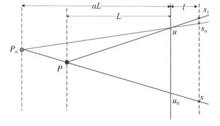
As the intensity of the THz waves along every light ray in the light field is consistent, we can calculate the imaging result of an arbitrary virtual object plane parallel with the original object plane by refocusing based on a chosen reference sub-image(u0,v0). During the refocusing process, for a pixel of the reference sub-image with coordinates (u0,v0,s,t),we calculate the spatial coordinate (sα,tα) of its corresponding pixel on the sub-image with spatial coordinate (u,v) following equation (1), while the angular coordinates of all points remain unchanged, as shown in Fig.3.

Fig. 2 Parametrization of the light field. (a) Pairs of points on two parallel planes; (b) parameterization of our system

Fig. 3 The resampling diagram of refocusing process.When changing the object distance, the spatial coordinate S of the reference sub-image u0 are constant, while the corresponding object point moves from P to Pα. According to the geometric principles,we can calculate the new coordinate Sα of sub-image u, which is different from the coordinate S1 corresponding to P
In the refocusing process, the coordinates calculated by equation (1) for resampling are generally not integers, so the corresponding intensity valueL(u,v,sα,tα) is generated by the inverse distanceweighted linear interpolation of four adjacent pixels’values.

where,Du,Dv,dsanddtare the unit lengths of the angular coordinates and the spatial coordinates respectively.Landlare the original object distance and imaging distance respectively.αis the ratio of the new object’s distance from the original one. For a specific light field,Dul/dsLandDvl/dtLare constant parameters, thus the resampling is determined byα, and the imaging resultLαcan be represented as the integration ofuandvafter resampling:

The magnificationMαof the refocused result can be calculated by:

3 Results and discussion
We choose a series of samples to verify the performance of our system. The focal lengthfof the camera is 44 mm, the original object distanceLis 750 mm, and the pixel sizeds×dtis 35 μm×35 μm.In our experiments, the sampling positions of the THz camera are distributed on a grid on theu-o-vplane. The size of the grid and the distances of adjacent points in theu-direction andv-direction are arbitrary chosen. The camera was moved to every position sequentially by the translation stage and recorded a series of sub-images to get the light field information of the target.
Due to the size and intensity of the THz source,the sub images are only partially visible and unclear.During the refocusing process, all sub-images are mapped on the new imaging plane, thus improving the field of view and the resolution of the synthetic result, as shown in Figs.4~6 (color online).
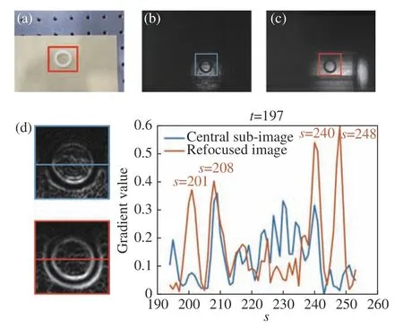
According to Fig.4 (d), the gradient values of the refocused image show four prominent peaks corresponding to the edges of the rubber ring while the central sub-image shows an undistinguished result,of which only the peak ofs=208 is clear for identification. The outer diameter and the inner diameter of the rubber ring are 47 pixels and 32 pixels respectively. Based on the refocusing parameters, the estimated diameters are 25.3 mm and 17.2 mm,which shows the potential of using refocused images for measurement. The ratio of the outer and inner diameters is 1.469, which is quite close to the reference truth-value 1.471. The deviation of size may be caused by the transformation of the rubber ring as well as the inaccurate object distance estimation, which can be effectively eliminated by precise calibration and reliable algorithm for focusing evaluation.

Fig. 4 A rubber ring in an envelope (grid size 9×3, Du=Dv=10 mm). (a) The rubber ring (outer diameter is 25 mm; inner diameter is 17 mm) and the envelope;(b) the reference sub-image (u=4, v=2); (c) the refocused image (αL=720 mm); (d) normalized gradient image of the labelled regions of (b) and (c), respectively and their gradient values of labelled horizontal lines corresponding to t=197

Fig. 5 A steel board with hollowed parts in a plastic box(grid size 9×1, Du=10 mm). (a) The steel board(length is 68 mm; width is 45 mm) and the plastic box; (b) the reference sub-image (u=5, v=1); (c) the refocused image (αL=730 mm); (d) intensity of labelled horizontal lines corresponding to t=174
In Fig. 5 (b) and Fig. 5 (c), the ratio of the widths of their field of views (intensity thresh: 0.25)is 106 pixels to 195 pixels, which is an expansion by a factor of 1.84. Fig.6(b) and Fig.6(c) show the improvement of resolution from 1.3 mm to 0.7 mm,which are the diameters of the finest wrenches that could be recognized.
To verify the flexibility of our method, we perform an experiment of the same sample with Fig.6,in which we move the sample rather than the camera for sub-image acquisition. The refocusing process shows similar results, as shown in Fig.7. This mode could be more applicable to some cases where the camera needs to be fixed. We can see the difference of noise in Fig.6 and Fig.7. There may be two reasons: first, the relative sample positions of two experiments are not identical; second, the movement of the target of Fig.7 also changes its relative position with the THz source, while the target of Fig.6 is relatively still with the THz source.

Fig. 6 Metal wrenches fixed on a polyvinyl chloride(PVC)board by tape. (grid size 9×7, Du=Dv=10 mm) (a)the wrenches (from left to right the diameters are 0.7 mm, 0.9 mm, 1.3 mm and 1.5 mm) and the PVC board; (b) the reference sub-image (u=3, v=4); (c)the refocused image (αL=680 mm); (d) the refocused image after histogram equalization.
With different sub-image as the reference view,the imaging position of the sample correspondingly changes, as shown in Fig.8(color online). According to Table.1, the mean parallax values per mm the camera moves are 1.825 pixel and 1.850 pixel foruandvdirections, respectively. Thus the corresponding estimations of the object distance are 731.8 mm and 721.9 mm, which conform well with the refocusing data. The parallax values generated from these different views could be used for specific 3D measurement with further calibration of the system.

Fig. 7 Metal wrenches (fixed camera and moving target,grid size 9×5, Du=Dv=10 mm). (a) The wrenches and the PVC board; (b) the reference sub-image(u=5, v=3); (c) the refocused image (αL=700 mm);(d) the refocused image after histogram equalization

Fig. 8 Refocusing images of different sub-views (two PVC bottles with liquid fixed by tape in a high-density polyethylene plastic box, grid size 9×2, Du=10 mm,Dv=20 mm). (a) The bottles (length is 50 mm; diameter is 13 mm; thickness is 2 mm) and the plastic box;(b) one primitive sub-image; (c)(d)(e)(f) are the refocused images with angular coordinates (4,1),(4,2), (1,1) and (9,1) respectively (αL=720 mm).

Tab. 1 Coordinates of sample pixels in different subviews
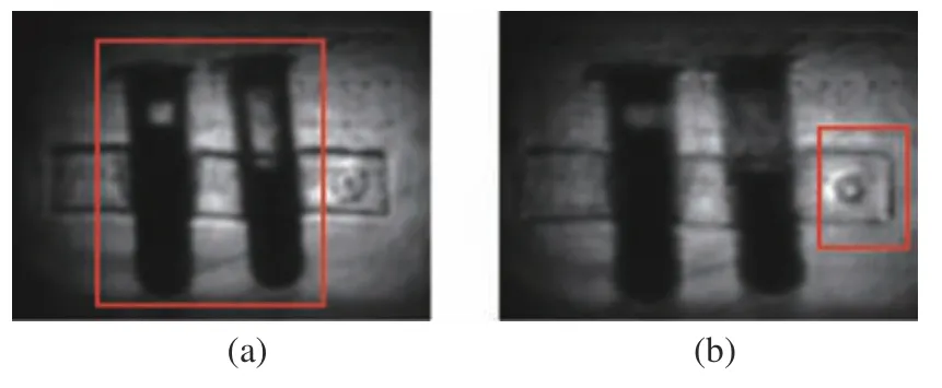
Fig.9 shows two imaging results with different refocusing depths. In Fig. 9 (a), the plastic bottles are in focus and the mark on the plastic box are unclear due to defocusing. While in Fig. 9 (b), the mark on the plastic box is in focus and the bottles become blurry. The refocusing results of different object distances expanded the depth of field and could also be used for depth estimation.

Fig. 9 Refocusing images of different depths. (a) The image focused on the bottles, αL=720 mm. (b) The image focused on the tape and the plastic box, αL=670 mm
For some situations where the obstructions could not be penetrated by THz waves, the synthetic process also works. As shown in Fig.10, by defocusing the wire mesh, we can restore the information of our target. In Fig.10 (c), the wire mesh is blurred and the steel holed cube is clearer than Fig.10 (b), especially the hole at the center.

Fig. 10 A steel holed cube blocked by a piece of wire mesh placed between it and the THz camera. (a)and (b) are two primitive sub-images showing the wire mesh and the obscured target respectively; (c)the refocused image
4 Conclusion
Terahertz imaging has many particular advantages for multiple applications. To exceed the limitation of the THz camera’s resolution and field of view as well as expand its functions, we build a THz light field imaging system of time sequential acquisition mode. Experiments show that compared with the original camera, the resolution, the field of view and the depth of field of the system are effectively improved. Besides, the system shows potential in restoration of obscured information, 3D measurement and depth estimation. Moreover, the system implementation and the image acquisition scheme are flexible, which can be modified to adapt different scenarios. Following points can be considered for further improvements based on this system and method: first, the refocusing process can be promoted by optimizing the interpolation and integration algorithm; second, the image acquisition scheme can be more efficient with adaptive design for different targets; third, the measurement function can be effectively developed by applicable calibration approaches.
