Time Domain Full Waveform Inversion Based on Gradient Preconditioning with an Angle-Dependent Weighting Factor
2022-12-27XIADongmingSONGPengLIXishuangTANJunXIEChuangWANGShaowenLIUKaiZHAOBoandMAOShibo
XIA Dongming , SONG Peng , , LI Xishuang, TAN Jun , XIE ChuangWANG Shaowen LIU Kai, ZHAO Bo , and MAO Shibo
1)College of Marine Geoscience, Ocean University of China, Qingdao 266100, China
2) The Laboratory for Marine Mineral Resource, Pilot National Laboratory for Marine Science and Technology (Qingdao),Qingdao 266100, China
3) Key Laboratory of Submarine Geosciences and Prospecting Techniques, Ministry of Education, Qingdao 266100, China
4) First Institute of Oceanography, Ministry of Natural Resources (MNR), Qingdao 266061, China
Abstract There are lots of low wavenumber noises in the gradients of time domain full waveform inversion (FWI), which can seriously reduce the accuracy and convergence speed of FWI. Thus, we introduce an angle-dependent weighting factor to precondition the gradients so as to suppress the low wavenumber noises when the multi-scale FWI is implemented in the high frequency. Model experiments show that the FWI based on the gradient preconditioning with an angle-dependent weighting factor has faster convergence speed and higher inversion accuracy than the conventional FWI. The tests on real marine seismic data show that this method can adapt to the FWI of field data, and provide high-precision velocity models for the actual data processing.
Key words full waveform inversion; low wavenumber noise; angle-dependent weighting factor
1 Introduction
Tarantola (1984, 1986)first proposed a time domain full waveform inversion (FWI)method based on the least squares optimization theory. This method uses the whole waveform including the travel time, amplitude and phase information of seismic records to reconstruct the velocity model of the underground medium. For an ideal observation system, the resolution can reach the same order of magnitude as the wavelength, guided by the Rayleigh criterion. So far,FWI has played a very important role in oil exploration in some areas (Masmoudi and Alkhalifah, 2018; Ohet al., 2018;Zhang and Alkhalifah, 2020).
Due to the strong nonlinearity of the objective function and the ‘Cycle skipping’ problem, FWI often falls into a local minimum in the iterative process. Bunks (1995)first proposed a multi-scale FWI method in time domain, which decomposed seismic data into different frequency ranges,and the inversion is conducted in those ranges successively from low-frequency (large-scale)to high-frequency (smallscale)to reduce the possibility of falling into a local extremum. Pratt and Shipp (1999)developed the frequency domain inversion to make multi-scale implementation more convenient. Boonyasiriwatet al. (2009)used a Wiener filter to implement multi-scale decomposition, and proposed a frequency band selection method. At present, multi-scale inversion has become a conventional inversion strategy for FWI in time domain.
In order to further improve the accuracy and adaptability of full waveform inversion, many scholars have done a lot of research works in recent years. Zhanget al. (2011,2012)proposed a gradient preconditioning method based on the seismic wave energy. This method had high inversion accuracy for deep layer mediums and did not need to carry out complex vector operations to approximate the Hessian matrix. Songet al. (2019)proposed a gradient preconditioning algorithm based on the transmitted wave energy, which further improved the inversion accuracy in deep layers. Wuet al. (2014)proposed a kind of FWI method based on seismic date envelope, which used the Hilbert envelope of seismic data instead of the low-frequency information to invert the large-scale structures in the velocity model and achieved good inversion results. Liuet al.(2020)proposed a convolution-based envelope inversion method by modifying the original envelope data, which could expand the overlap region between the observed and modeled envelope data. Chen and Chen (2016)proposed the FWI method for thesecond-order time integral wavefield, which could effectively enhance the existing low-frequency information in seismic data. Wang and Han (2018)proposed an FWI method based on the total vertical variation constraint, which could effectively reconstruct the discontinuous interface in the velocity model, and could obtain a higher inversion accuracy especially under complex geological conditions. Yaoet al. (2018)separated the migration mode and tomography mode in the plane wave domain with an angle-dependent filtering technique and achieved effective and robust inversion results. Fanget al. (2018)developed the linear Born inverse scattering imaging condition and suppressed low-wavenumber artifacts effectively.Yaoet al.(2019)developed a reflection-wave-form inversion (RWI)method, which could reduce the dependence on the initial velocity model effectively and improve the inversion accuracy significantly. Wu and Alkhalifah (2017)developed the RWI method by splitting the velocity model into background and perturbation components, which further reduced the dependence on the initial velocity model.Wanget al. (2020)developed a frequency-domain energy norm Born scattering RWI algorithm, which could be better used in the inversion of the long wavelength velocities.
However, there are still some problems in FWI now,such as slow convergence speed and low inversion accuracy. The reason is that in each iteration of FWI, the gradient is calculated by the cross-correlation of the forward time propagated wavefield from the sources and reverse time propagated wavefield from the residual gathers. The cross-correlation calculation of the two wavefields will inevitably produce lots of low-wavenumber noises, which will result in slowing the convergence and reducing the accuracy of inversion.
In recent years, some scholars have developed some gradient preconditioning methods based on scattering-angle treatments (Alkhalifah, 2015a, 2015b, 2016; Wu and Alkhalifah, 2017). In order to suppress the low-frequency noise in the gradient of least square reverse time migration (LSRTM), Yang and Zhang (2018)introduced an angle-dependent factor into LSRTM, realized the gradient preconditioning and obtained good migration imaging results. In this paper, an algorithm is introduced into the FWI, which effectively eliminates the low-frequency noise information in the gradient, and significantly improves the convergence speed and inversion accuracy of the FWI. The effectiveness of the proposed method is verified by applying the approach to synthetic and field data.
2 Gradient Calculation of FWI in Time Domain
The objective function of FWI based on the least-squares optimization can be defined as follows:

In Eq. (1),Nsis the total number of shots,sn(x,t)is the source wavelet of thenth shot,dnis the observation record for thenth shot, andp(v,sn)is the synthetic seismic record takingsn(x,t)as the source based on the velocity modelv, which satisfies the acoustic equation:

The method of FWI in the time domain can be summed up as finding an optimal velocity modelvto minimize the objective function. FWI finds the optimal model through gradient-based methods. Tarantola (1984, 1986)derived the gradient calculation algorithm based on Born approximation. When the density is constant, the gradient can be written as follows:

The gradient calculation formula of FWI in time domain contains two wavefield functions, a forward wavefieldp(x,t,xs)and a reverse-time wavefieldψ(x,t,xs).p(x,t,xs)can be obtained by a numerical forward modeling of the acoustic wave equation with the seismic wavelet used as a source.ψ(x,t,xs)can be obtained by reverse-time simulation with the residual record δp(x,t,xs)used as reversetime disturbance. Here δp(x,t,xs)is the difference between the modeled seismic record and the observed seismic one.
It can be seen from Eq. (3)that the calculation of FWI gradients requires the cross-correlation calculation between forward wavefield and time reversed wavefield, which will inevitably lead to a large number of low wavenumber noises.These low wavenumber noises seriously affect the convergence rate, accuracy and efficiency of FWI.
3 Gradient Weighting Based on an Angle-Dependent Factor
Yang and Zhang (2018)introduced the angle-dependent weighting factor in the least square reverse time migration,realized the gradient preconditioning of the least square reverse time migration, and eliminated the low wavenumber gradient noises effectively. In this paper, this idea is introduced into the FWI.
Firstly, we define a scattering angle (as shownθin Fig.1),which is the opening angle between the line from source point to the scattering point and the line from receiver point to the scattering point. The range ofθis usually between 0 and π.kSandkRrepresent the wavenumbers related to the source and receiver rays, respectively. Milleret al. (1987)and Thomas and Graham (2011)discussed the relationship between the wavenumberkof gradient and scattering angleθ, as shown in Eq. (4):
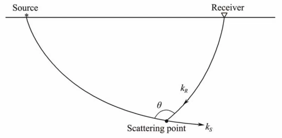
Fig.1 A diagram showing the scattering angle.

Hereλis the wavelength of seismic wave, which is determined by the velocity and frequency.is the direction of the wavenumber vectork.
It can be seen from Eq. (4)that the large scattering angles correspond to the low wavenumber information, while the small scattering angles correspond to the high wavenumber information. Therefore, in order to suppress the low wavenumber noises, an angle-dependent weighting factor cos2(θ/2)is introduced into the gradient calculation formula to get a weighted gradient:

From Eq. (5), we can see that the smallerθis, the larger the weighted gradient is, andvice versa. Especially whenθis π, the weighted gradient is 0.
Obviously, to use Eq. (5), we must first determine the value ofθ, which will cause huge computing costs. In order to avoid the direct calculation ofθ, the cross-correlation between the wavefield of source and the wavefield of residual record is calculated first by Eq. (6):

By using a Laplace operator, we can get:

Namely,

By comparing Eq. (5)and Eq. (8), we can get the following equation:

It can be seen from Eq. (9)that the calculation of the weighted gradient in full waveform inversion by Eq. (5)can be converted into a Laplacian operator of the cross-correlation between forward wavefieldpand reverse-time wavefieldψ, instead of the direct calculation of angleθin Eq. (5).
It is worth noting that although the low wavenumber noise in the gradient section can be effectively suppressed by the gradient preconditioning based on angle-dependent weighting factor (GPBAWF), some low wavenumber effective information in gradient section can also be suppressed at the same time. Therefore, only for FWI in some high frequencies (in this paper, we recommend to implement GPBAWF from the third frequency), the gradient preconditioning method is recommended, and even if in these cases, it is expected to do only one iteration for each frequency band,otherwise it may lead to instability. In summary, the whole inversion strategy about FWI with GPBAWF we recommended is that: for the first and second frequency, conventional FWI is still needed to be implemented, and from the third frequency, FWI with GPBAWF is implemented only for the first iteration.
4 Model Tests
In this paper, a Marmousi velocity model with a water layer of 500 m was used for inversion test (as shown in Fig.2). A Rayleigh wavelet with a dominant frequency of 20 Hz was used as the source. The observation system is given by the full coverage of receivers on the surface and fixed receiving points. A total of 461 shots of seismic records (the 231st shot of seismic records is shown in Fig.3)were simulated as the observed seismic records of inversion and each shot record included 461 traces. The shot interval and trace interval are both 20 m, and the shot point depth and receiver depth are both 20 m too.
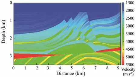
Fig.2 Marmousi velocity model.
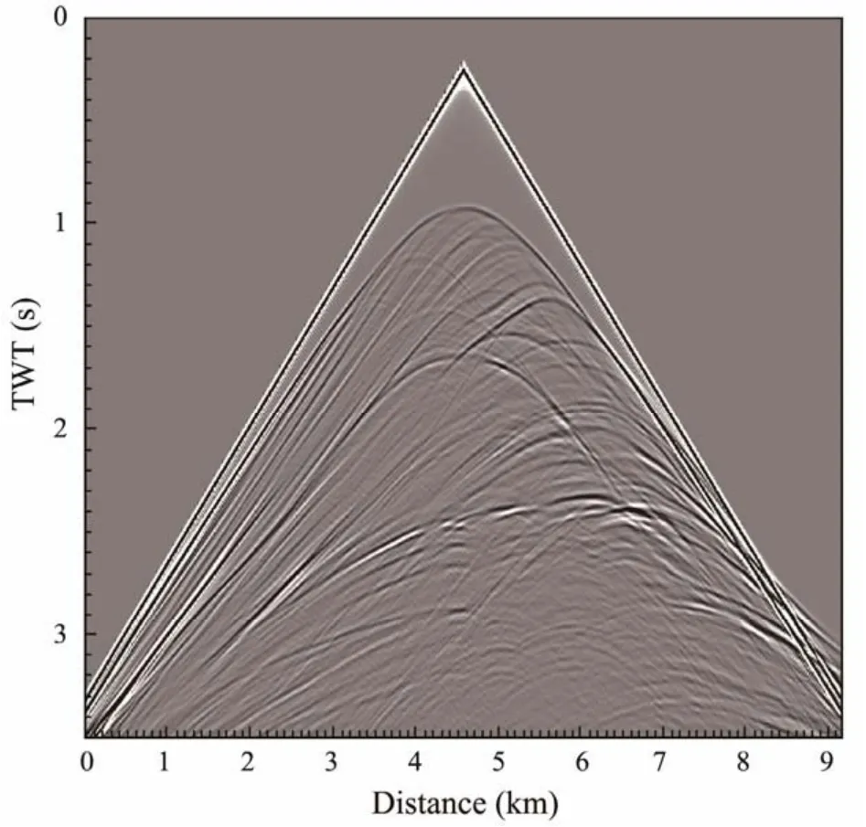
Fig.3 The 231st shot record.
A smoothed model was used as the initial inversion model (as shown in Fig.4). There were four inversion frequency bands, and the high cut-off frequencies were 5 Hz, 8.25 Hz, 13.63 Hz, and 30 Hz.
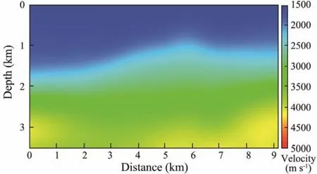
Fig.4 The initial velocity model.
In order to ensure the stable convergence of inversion,GPBAWF was not applied in the first two frequency bands,and only conventional FWI was implemented with 20 iterations for each frequency band.
For the first iteration of the third frequency band, FWI with GPBAWF was implemented, and the gradient section with and without GPBAWF are shown in Figs.5 and 6, respectively.
Comparing Figs.5 and 6, we can see that there is less low-wavenumber information in Fig.5, which will lead to faster convergence speed and higher inversion accuracy.
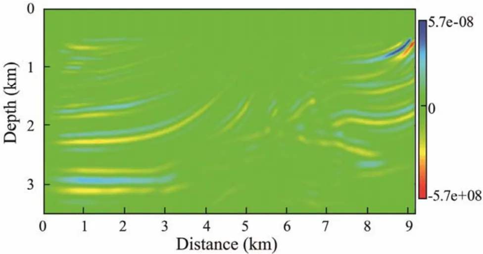
Fig.5 Gradient section with GPBAWF.
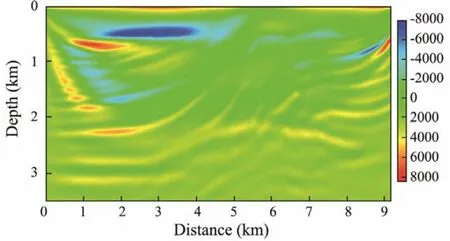
Fig.6 Gradient section without GPBAWF.
Fig.7 shows the result of FWI in the third frequency band with one iteration of GPBAWF and four iterations of conventional inversion. Fig.8 shows the result in the third frequency band with five iterations of conventional inversion (without GPBAWF).
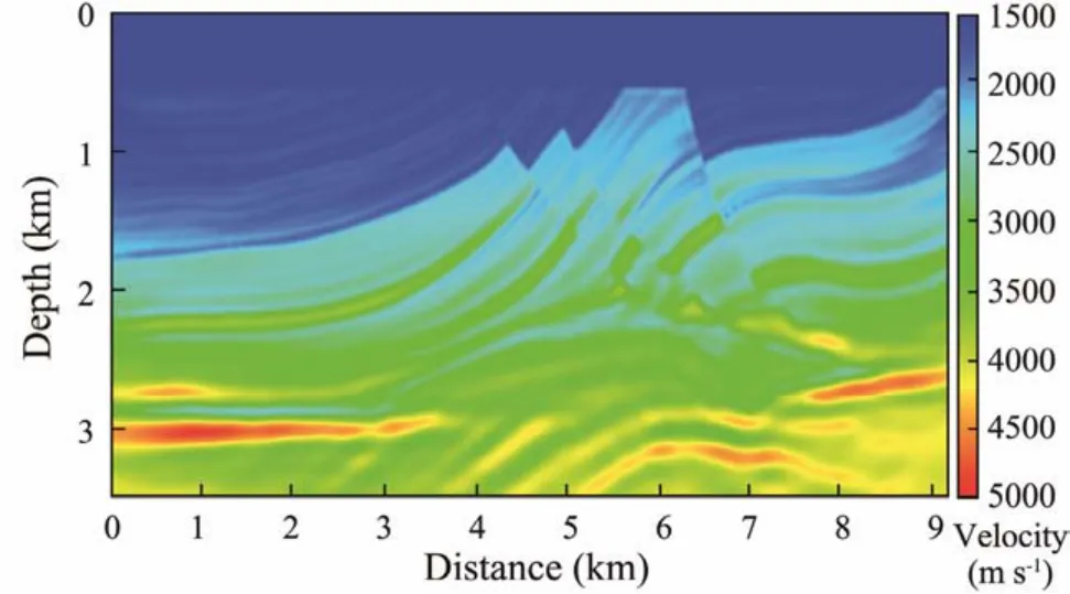
Fig.7 Inversion result by 1 iteration of FWI with GPBAWF and 4 iterations of conventional inversion in the third frequency band.
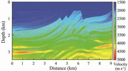
Fig.8 Inversion result by 5 iterations of conventional inversion in the third frequency band.
Comparing Figs.7 and 8, we can see that the inversion result in which we used GPBAWF is clearer and closer to the real model than that of the conventional inversion, especially in the deep part, which demonstrates that the FWI with GPBAWF has higher accuracy.
The vertical velocity sections at 3000 m and 6000 m of the inversion results in Figs.7 and 8 are extracted and compared with the real velocity of the trace, as shown, respectively, in Figs.9 and 10.
We can see from Figs.9 and 10 that the velocity curves of FWI with GPBAWF are closer to the real velocity curves than the conventional FWI.
Fig.11 shows the inversion results of FWI by 10 iterations in the third and fourth frequency bands, and for each frequency band, the first iteration includes GPBAWF. Fig.12 shows the conventional FWI result by 20 iterations in the four frequency bands. Comparing the two figures, it can be seen that even if the number of iterations in high-frequency band is only half of that of conventional inversion,the result of FWI with GPBAWF is still better than that of conventional FWI.
In order to further compare the accuracy of the two inversion methods, the traces at the positions of 3000 m and 6000 m of the inversion results in Figs.11 and 12 are extracted respectively and compared with the real velocity,as shown in Figs.13 and 14.
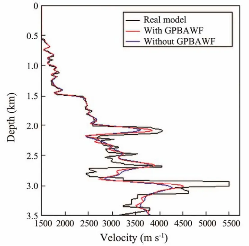
Fig.9 The comparison of FWI results with real velocity at location 3000 m which inversion velocity is extracted from Figs.7 and 8.
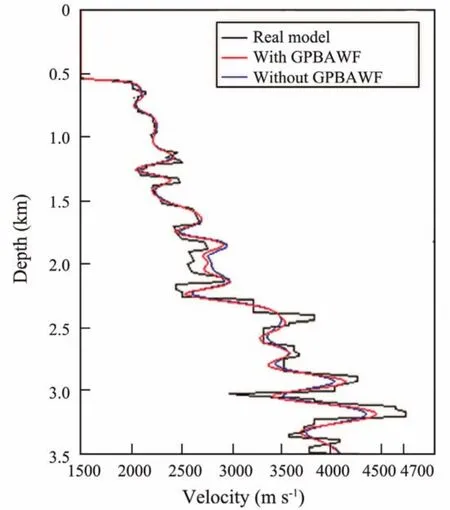
Fig.10 Same as Fig.9 but for 6000 m.
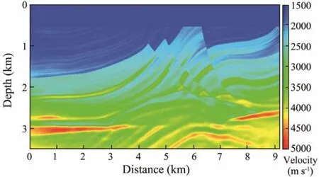
Fig.11 Inversion result by 1 iteration of FWI with GPBAWF and 9 iterations of conventional inversion both in the third and fourth frequency bands.
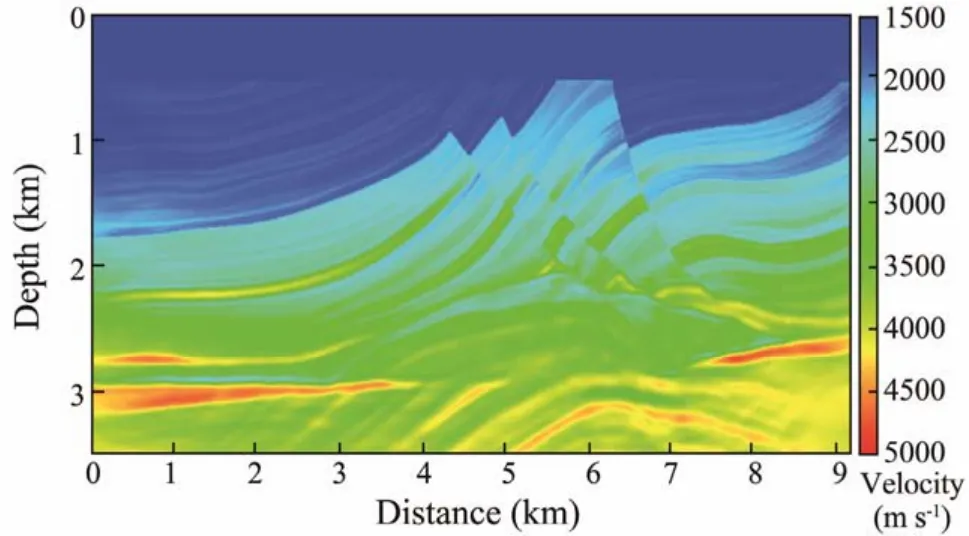
Fig.12 Inversion result by 20 iterations of conventional inversion in the four frequency bands.
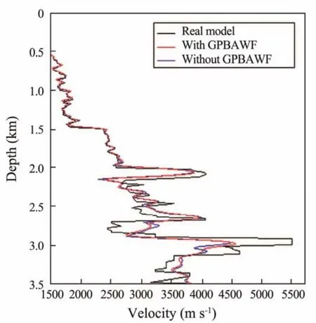
Fig.13 The comparison of FWI results with real velocity at location 3000 m which inversion velocity is extracted from Figs.11 and 12.
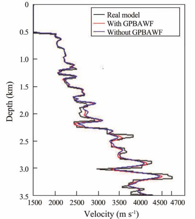
Fig.14 Same as Fig.13 but for 6000 m.
It can be seen from Figs.13 and 14 that the velocity curve of FWI with GPBAWF is still closer to the real velocity curve at both 3000 m and 6000 m, which further demonstrates that the FWI with GPBAWF has higher inversion accuracy and convergence speed.
5 Field Data Application
A field seismic prospecting line in a certain sea area of the China Sea was selected for the test. There were 3831 shots in total and each shot had 648 receivers. The sampling intervals for the shots and receivers were 37.5 m and 12.5 m respectively. The minimum offset was 187.5 m. The depth of shots and receivers were both 12.5 m. The record length of the shot gather was 7 s. Wild noise attenuation,shallow muting and multiple elimination were applied to the data before used to the test for FWI (the 1900th shot gather is shown in Fig.15).
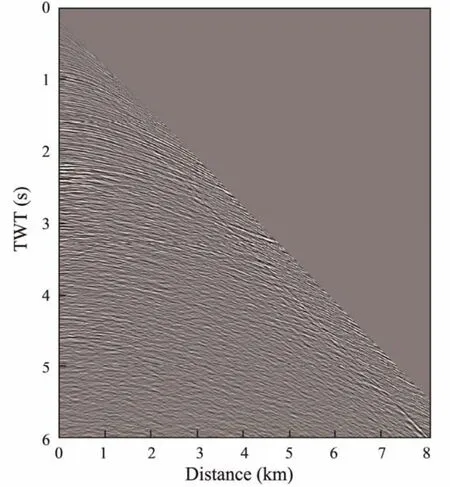
Fig.15 The 1900th shot record.
The seismic wavelet is extracted by multi-trace statistics averaging method as the inversion source (as shown in Fig.16), and the prestack depth migration velocity section is used as the initial velocity model (as shown in Fig.17).Then, we perform the FWI with GPBAWF in four frequency bands and the highcut-off frequencies are 5, 10, 15 Hz, and 35 Hz respectively. 50 iterations were conducted for each frequency band and only in the last two frequency bands GPBAWF was applied for the first iteration. The final inverted model is shown in Fig.18.
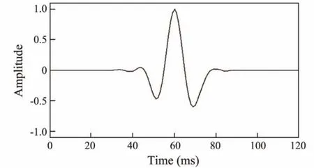
Fig.16 The seismic wavelet used as the source.
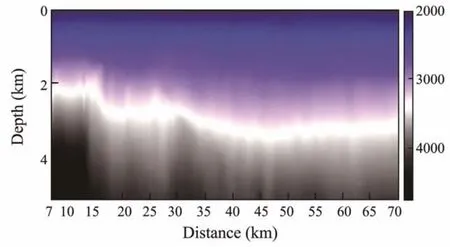
Fig.17 The initial velocity model.
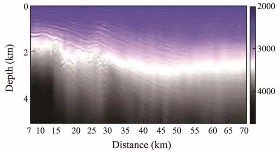
Fig.18 The final inverted velocity model.
Figs.19 and 20 show the reverse time migration section based on the initial and inverted velocity models, respectively. From Figs.19 and 20, we can see that the section based on the final inverted model is clearer than that based on the initial model. Moreover, by comparing Figs.18 and 20, it can be found that the final inversion results were in high accordance with tectonic characteristics of the migration section, indicating that the method we proposed is highly applicable to the FWI for field data processing.
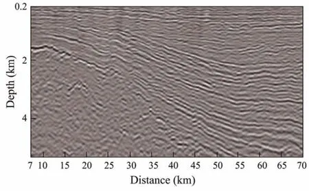
Fig.19 Reverse time migration section based on the initial model.
Figs.21a and 21b show the imaging gathers based on the initial model and the inversion model, respectively. The position of the imaging gathers is 54 km. In the imaging gathers, the position of zero in horizontal axis is the current imaging position and every trace is imaged by one shot gather. The horizontal distance is the distance between the current imaging position and the current shot position. In theory, the more accurate the model is, the closer to the horizontal the events in the imaging gather should be. We can see that the events in the Fig.21b are closer to the horizontal than that in Fig.21a, which can demonstrate that the inverted model is more accurate than the initial model.
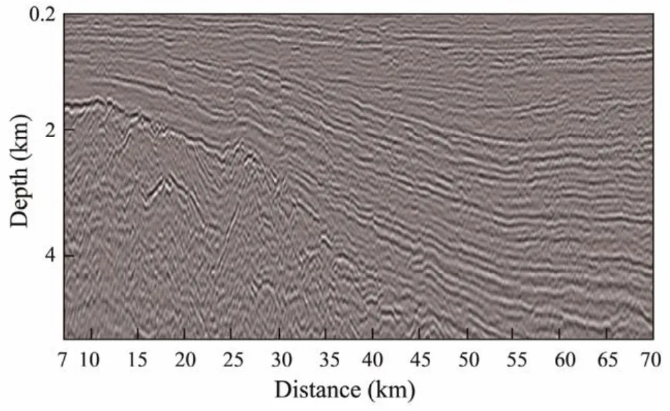
Fig.20 Reverse time migration section based on the inverted model.
6 Conclusions
An angle-dependent weighting factor is introduced into FWI to suppress the low wavenumber noises effectively.Model tests showed that FWI with the gradient preconditioning based on angle-dependent weighting factor had high inversion accuracy and convergence speed than conventional FWI. The result of real marine seismic data processing shows that this method can adapt to FWI for field data,and provide high-precision velocity models.
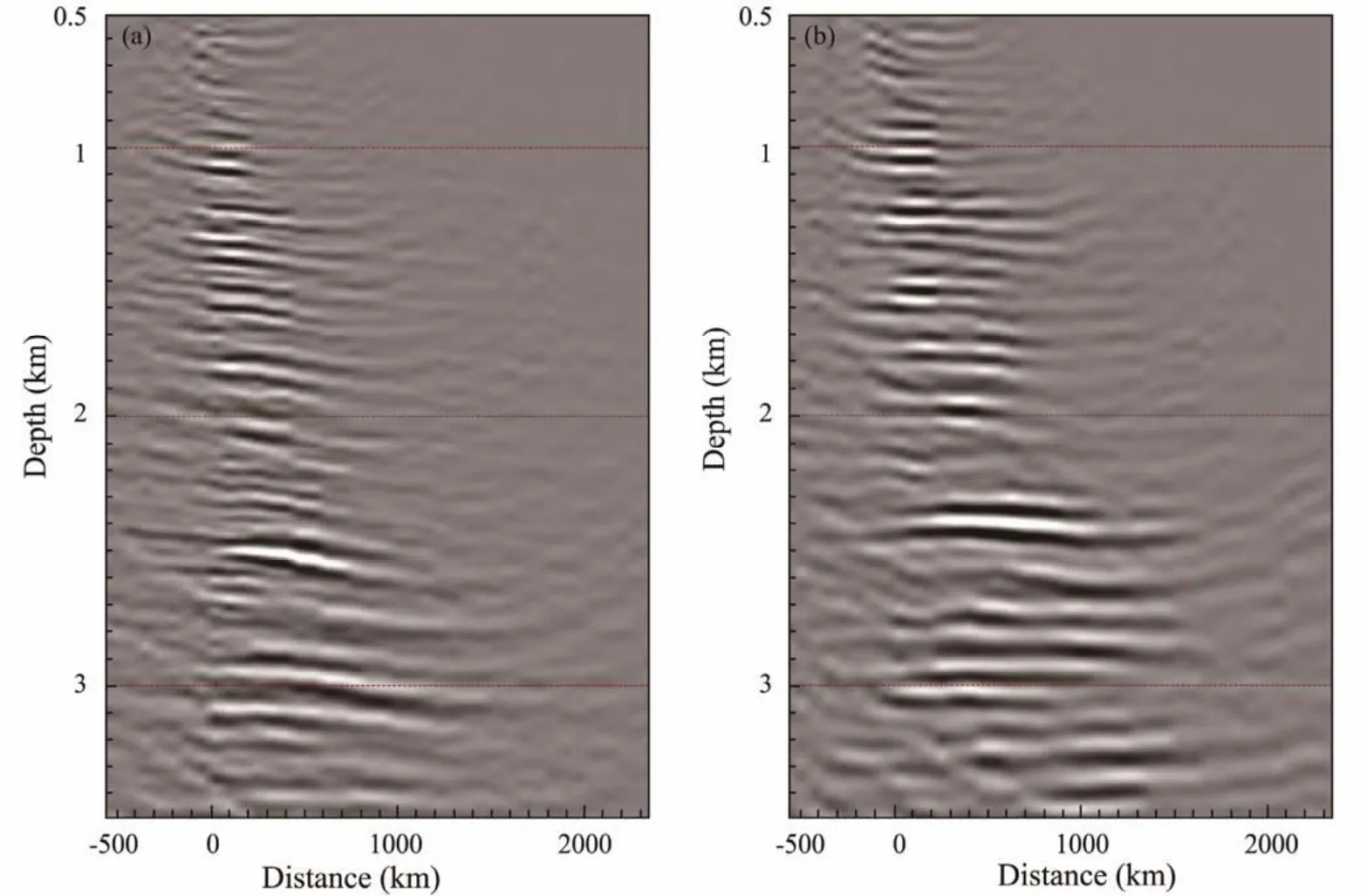
Fig.21 Imaging gathers. (a), based on the initial model; (b), based on the inverted model.
Acknowledgements
This research is jointly funded by the National Natural Science Foundation of China (No. 42074138), the Wenhai Program of the S&T Fund of Shandong Province for Pilot National Laboratory for Marine Science and Technology(Qingdao)(No. 2021WHZZB0700), and the Major Scientific and Technological Innovation Project of Shandong Province (No. 2019JZZY010803).
杂志排行
Journal of Ocean University of China的其它文章
- A Theoretical Model for the Microwave Emissivity of Rough Sea Surfaces
- Mechanism of Regional Subseasonal Precipitation in the Strongest and Weakest East Asian Summer Monsoon Subseasonal Variation Years
- Analytical and Experimental Studies on Wave Scattering by a Horizontal Perforated Plate at the Still Water Level
- Theoretical Prediction of the Bending Stiffness of Reinforced Thermoplastic Pipes Using a Homogenization Method
- Penetration Resistance of Composite Bucket Foundation with Eccentric Load for Offshore Wind Turbines
- Application of Converted Displacement for Modal Parameter Identification of Offshore Wind Turbines with High-Pile Foundation
