Penetration Resistance of Composite Bucket Foundation with Eccentric Load for Offshore Wind Turbines
2022-12-27ZHANGPuyangQIXinYANRuiyangXUYunlongLEConghuanandDINGHongyan
ZHANG Puyang , QI Xin YAN Ruiyang XU Yunlong LE Conghuan and DING Hongyan
1)State Key Laboratory of Hydraulic Engineering Simulation and Safety, Tianjin University, Tianjin 300072, China
2)School of Civil Engineering, Tianjin University, Tianjin 300072, China
Abstract The penetration of the composite bucket foundation (CBF)is crucial in its construction process. In actual projects, the foundation is inevitably subjected to eccentric load caused by towers and turbines, as well as wind, wave, and flow, during the one-step installation. Moreover, the eccentric load is bound to affect the penetration method and penetration resistance of the foundation. To examine the above-mentioned issues, the penetration resistance of CBF with eccentric load was calculated and analyzed based on model tests, and the seepage field of the CBF under eccentric load was analyzed using ABAQUS. The influence of different magnitudes of eccentric load and various offset strategies on penetration resistance was analyzed, and the theoretical and measured values were compared. The result indicated that the negative pressure of the offset room was found to be smaller than that of other rooms when the CBF penetrated the soil under eccentric load. The penetration resistance of CBF under eccentric load was larger than that without eccentricity, and the larger the eccentric load is, the greater the penetration resistance. The influence of different eccentric load offset strategies on penetration resistance was found to be negligible. The calculated penetration resistance under eccentric load was in good agreement with the measured value.
Key words composite bucket foundation (CBF); eccentric load; pore water pressure; penetration resistance; seepage
1 Introduction
In recent years, with increasing demand for energy from all walks of life, traditional non-renewable fossil energy cannot replenish sufficiently fast and can no longer meet the worldwide needs of development. Moreover, the development of renewable energy sources is imminent due to the increasingly prominent problem of environmental pollution, among which wind energy plays an important part because it is a clean and renewable energy source (Renet al., 2022; Zhanget al., 2022). As a new type of offshore wind power foundation, the composite bucket foundation(CBF, see Fig.1)exhibits the characteristics of economic feasibility and environment-friendly work principles (Zhanget al., 2013b; Heet al., 2017; Dinget al., 2019, 2022),thus demonstrating an extensive application prospect. The first suction-type bucket foundation is the Europipe 16/11-E large jacket platform studied by the Norwegian Geotechnical Institute in 1994. Moreover, since the first installation of bucket foundations in 2002 in Denmark, an increasing number of bucket foundations have been used for wind power generation (Fuet al., 2015; Wanget al., 2019).
Notably, the installation of the bucket foundation is the key point that affects its ultimate bearing capacity. A new type of foundation with bulkheads was proposed to facilitate a smooth installation process. With seven rooms inside the bucket, the pressure of each room can be controlled individually to balance the foundation (Huet al.,2018; Jiaet al., 2018). Furthermore, the proposed foundation has a good performance considering motion characteristics and towing reliability during the wet-tow construction process (Zhanget al., 2013a). Extensive research efforts have also been devoted to theoretical analysis, numerical simulation, and experiments on the penetration process, particularly the suitable pressure range during installation. On the one hand, insufficient suction cannot lower the foundation to the specified depth. On the other hand,excess suction leads to soil plugs in the bucket, which can result in installation failure. Therefore, evaluation of the penetration resistance and negative pressure is necessary for the smooth operation of the bucket foundation. The penetration resistance of the bucket foundation in clay can be accurately predicted due to its simple penetration mechanism, and several studies related to seepage field and penetration resistance of bucket foundations in the sand have also been performed. According to literature,seepage can significantly reduce the inner friction of the bucket wall and also its tip resistance (Tran and Ran- dolph,2008; Zhanget al., 2018; Fuet al., 2020; Chenet al., 2021).Several methods to evaluate the penetration resistance are also available. Senders and Randolph (2009)presented a CPT-based method (CPT is the abbreviation of cone penetration test)to estimate the penetration resistance and suction required during the installation of bucket foundations in sand. Houlsby and Byrne (2005)proposed that the penetration resistance could be calculated on the basis of the bearing capacity theory with friction angle. Zhanget al.(2018)studied the effect of pore water seepage on the soil resistance to CBF by using the finite element software ADINA and derived the formula for calculating penetration resistance considering the seepage effect. However, the above-mentioned studies on the seepage field and penetration resistance of bucket foundations did not consider the effect of eccentric loads, while the eccentric moment on CBF exists during the one-step installation with the tower and turbine. Moreover, considering the CBF subjected to loads, such as wind, waves, and flow during installation,the research on seepage field and penetration resistance of the bucket foundation under eccentric load is of considerable importance for integral installation, as shown in Fig.2.
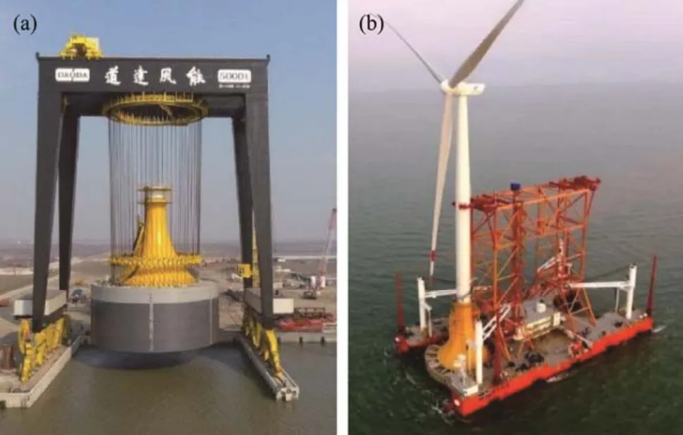
Fig.1 Photographs of the composite bucket foundation. (a),transition section; (b), wet-tow construction process.
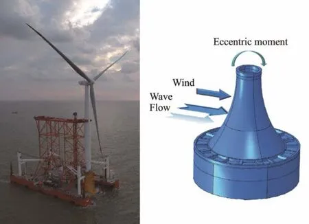
Fig.2 Schematic illustration of eccentric load on CBF.
This study mainly aims to propose the calculation method of the penetration resistance of CBF under eccentric loads with different magnitudes. The experiments conducted to study the effects of load grade on penetration speed and different magnitudes of the eccentric load on the pore water pressure are respectively discussed in Sections 2 and 3,and the calculations of the penetration resistance under different magnitudes of eccentric load are presented. The seepage field under different magnitudes of eccentric load and various eccentric load offset strategies is revealed in Section 4, and the distribution patterns of side friction of each room under different eccentric load offset strategies are compared. The conclusions are provided in Section 5.
2 Test Overview
2.1 Test Model and Soil Parameters
A model with a geometric scale of 1:35 was used in the test, and the scales of other physical quantities involved in the test are listed in Table 1 based on the Froude criterion of gravitational similarity. The prototype was a 6.45 MW CBF in a certain area of Jiangsu. The bucket wall,bulkheads, and internal skirt comprised steel with a thickness of 0.0015 m. The bucket lid and the transition section comprised plexiglass with a thickness of 0.01 m. The test model and dimensions are shown in Fig.3.
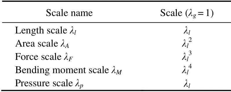
Table 1 Scaling laws based on the Froude criterion of gravitational similarity
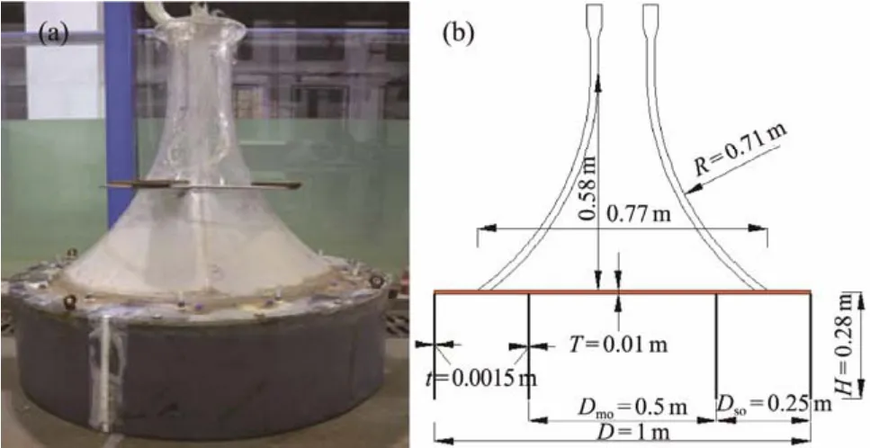
Fig.3 Test model. (a), physical prototype; (b), model magnitude.
The soil used in the test was sand obtained from a certain coastal area in Fujian, most of which was medium and fine sand. Shear tests were conducted on the sand under different vertical pressures to obtain the shear strength envelope of the soil. The internal friction angle of the soil was 34.4˚ and the cohesion was 1.16 kPa. The height, length,and width of the soil tank were 1.3, 2, and 2 m, respectively.For each layer of sand placed in the soil preparation stage,a water injection valve was opened to saturate the soil from bottom to top to eliminate the entrapped air. The next layer of sand was not put in until the soil was saturated.This operation was repeated and the pore water pressure sensors were embedded in place. All the aforementioned details were used to accelerate soil saturation and consolidation, ensure that the soil parameters are as identical as possible during each test, and reduce errors. The soil parameters after being maintained are listed in Table 2.
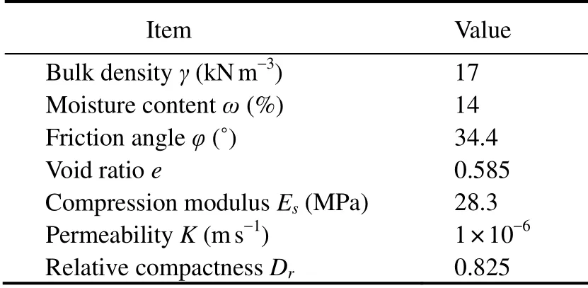
Table 2 Soil parameters
2.2 Test Equipment and Process
Applying a fixed bending moment to the CBF is difficult; such an application can be realized by the method shown in Fig.4 as follows, A ballast of specified mass,which can be regarded as part of the CBF, is placed directly above Room Table 1of the CBF, and this load can be equivalent to a bending moment and a concentrated load acting on the center of mass. The eccentric load can be applied by using the above-mentioned method; the required mass of the ballasts is 9.78, 16.5, and 21.96 kg, according to the calculation.

Fig.4 Application method of eccentric moment.
The penetration test comprises the following steps. First,a crane is used to place the CBF in the center of the soil tank, and its horizontal placement is ensured. The valves of each room are then opened to settle down the model under its weight. Second, the eccentric load is applied, and the change in inclination and displacement of the foundation under eccentric load is observed and recorded. Third,the CBF is connected to the vacuum pump and the barometers, and the foundation is leveled to within 0.25˚ inxandydirections through the vacuum pump. Finally, the CBF penetrated the soilviasuction, which is increased step by step. Furthermore, the water level in the soil tank is maintained during the penetration process, and the data of negative pressure of each room, displacement, inclination, and pore water pressure on the CBF are recorded in each test. This approach facilitates subsequent analysis and ensures the penetration of the foundation into the soil step by step within the inclination range. The test model and equipment are shown in Fig.5.

Fig.5 Test equipment.
2.3 Test Conditions and Sensor Arrangement
The test was divided into two stages and six test conditions to examine the influence of load grade and eccentric load in the penetration process of CBF. On the one hand,setting different ΔPvalues for comparison is necessary to explore the influence of different loading grades on the penetration process. The applied negative pressure in the entire penetration process is ensured to be less than the theoretical calculation value of the critical negative pressure, which may lead to soil seepage failure. On the other hand, the loading grade values are 1, 1.5, and 2 kPa in test conditions Q1, Q2, and Q3, respectively, considering the range and precision of the vacuum pump used in the test to control the penetration time within a certain range.
The loading grade mentioned in this paper refers to the additional negative pressure value for the foundation to continue soil penetration when the penetration resistance value is larger than the applied suction value, resulting in the interruption of penetration. For example, when the applied total negative pressure value is 6 kPa and the penetration depth is 0.15 m, the total negative pressure is increased to 7.5 kPa to facilitate the continuous sinking of the foundation, and the increased negative pressure value of 1.5 kPa is the so-called loading grade.
In the penetration process of CBF, the eccentric load mainly comes from the eccentric bending moment produced by the mass of the turbine. The total weight of the turbine in the prototype is approximately 430 t, and the eccentric bending moment is approximately 15 MN m, which can be calculated in Table 3. The coordinate system of the tower top is shown in Fig.6, corresponding to the eccentric load of 10 N m in the test, and the required mass of the ballast is 9.78 kg, according to the calculation.

Table 3 Weight and center of gravity coordinates of the tower top
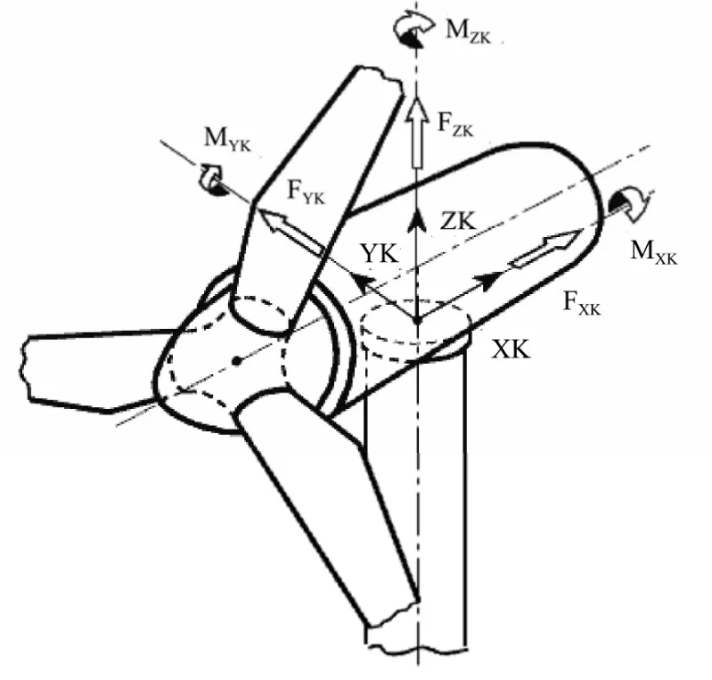
Fig.6 Coordinate system of the tower top.
The influence of the 10 N m eccentric load on the test results may be insignificant. Thus, the eccentric load values under the normal use limiting state (approximately 75 MN m)and the ultimate state (approximately 120 MN m)of the turbine are selected for research, respectively corresponding to the eccentric loads of 50 and 80 N m in the test. Therefore, the independent variables in the working conditions N1, N2, and N3correspond to the eccentric load magnitudes, which are 10, 50, and 80 N m, respectively, and the load grade is 2 kPa.Moreover, the controlled trial without eccentric load was performed.
Six pore water pressure gages (three inside and three outside the bucket wall)are embedded in the soil tank where the eccentric load is located. The location and number of the pore water gages are shown in Fig.7. All rooms are connected to the barometer to monitor and record the changes in negative pressure during the penetration process.

Table 4 Test conditions
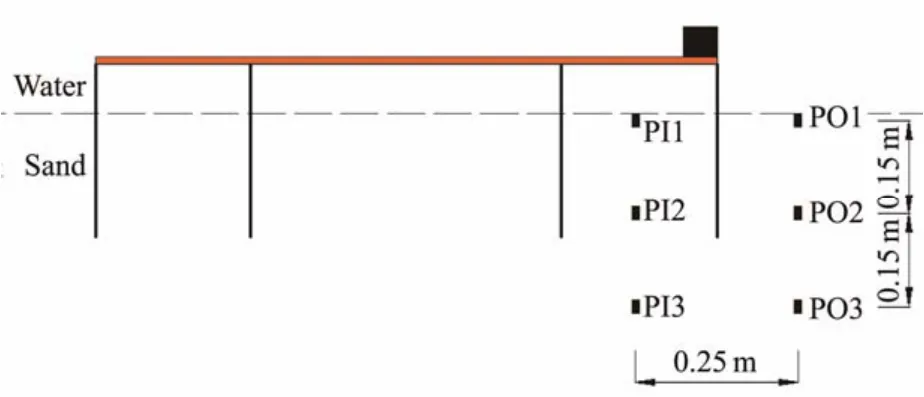
Fig.7 Arrangement of sensors.
3 Test Results
3.1 Penetration Depth
Fig.8 shows the variation curves of penetration depth with time under test conditions Q1, Q2, and Q3. The figure demonstrates that the entire penetration process of CBF by suction under different test conditions can be divided into the following five steps. 1)A closed environment is formed in the bucket, the foundation begins to penetrate the sand, the pressure difference between the top of the bucket and the outside increases, and the settlement rate of the bucket foundation gradually increases. 2)The depth of the bucket settlement is relatively shallow, the pressure driving force and the settling resistance are balanced, and the bucket penetration rate is uniform. At this point, the main process is to pump out the original water inside the bucket to facilitate the sinking of the foundation. 3)The curve inflection point appears at this stage. With the increase in negative pressure, the penetration speed changes from slow to fast. It is speculated that with the increase in the depth of the bucket, the sinking speed decreases rapidly due to the increase in the resistance. However, at the same time, the seepage effect is gradually enhanced, and the sinking resistance is then reduced. At this point, the water pumped out is mainly the water in the soil. 4)The slope of the curve is steepest at this stage, considering the reduction in seepage resistance and the penetration rate reaching its peak. 5)At the end of this stage, foundation penetration depth does not undergo significant changes despite the increase in negative pressure. Therefore, the suction installation is completed. Comparative analysis of the curves of each test condition indicates that the bucket penetrated the soil 0.06 m in tests Q1, Q2, and Q3after the bucket settled down through its weight and leveling. The bucket finally penetrated the soil 0.233 m in 13875 s in Q1.The final penetration depth was 0.245 m in Q2, which took 12435 s, while the bucket penetrated the sand 0.268 m in 10559 s in Q3. Within a certain range, a high loading grade induces a fast penetration rate of the foundation and a large penetration depth. Therefore, the load grade of N1, N2, and N3in subsequent test conditions was 2 kPa.
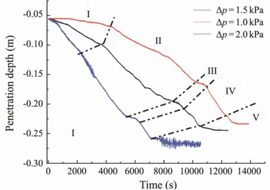
Fig.8 Time history of the penetration depth under different load grades.
3.2 Analysis of Pore Water Pressure Under Different Eccentric Loads
Fig.9 refers to the pore water pressure variations over time at different testing points inside the bucket labeled as PI1, PI2, and PI3. PI1 is located on the surface of the soil,while PI2 and PI3 are located at 0.15 and 0.3 m from the soil surface, respectively. The value of pore water pressure decreases with the increase in negative pressure; the pore water pressure correspondingly changes with the negative pressure.
Comparative analysis of the curves of pore water pressure at different test points in Fig.9 indicates a similar trend in each curve: the change in pore water pressure is substantial when close to the soil surface.
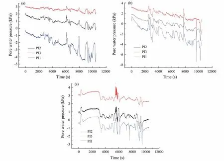
Fig.9 Time history of pore water pressure inside the bucket under conditions N1 (a), N2 (b), and N3 (c).
Fig.10 shows the curves of pore water pressure obtained by using sensors PO1–PO3 placed at 0.125 m from the bucket wall as a function of time under condition N2. The figure reveals that the penetration process has minimal effect on the pore water pressure at a certain distance away from the tip of the bucket wall (Zhanget al., 2017).
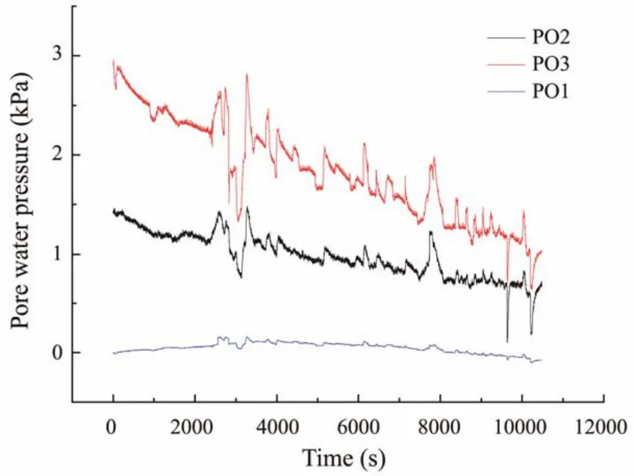
Fig.10 Time history of pore water pressure outside the bucket under condition N2.
3.3 Changes in Total Suction Pressure During Penetration
Fig.11 shows the curves of penetration depth and total suction pressure when the bucket penetrated the sand by suction under condition N1, and the curves do not include the self-weight installation process. The penetration process was divided into six steps, which are distinguished by different total suction pressures, as shown in Fig.11. The suction pressure increased, and the succeeding penetration step started when the displacement of the CBF was less than 0.0005 m within 3 min. After the bucket settled under its own weight, the penetration depth was 0.05 m, and the depth changed to 0.06 m after leveling. This finding indicates that the penetration rate was slow at the beginning.This slow pace is attributed to the relatively small negative pressure applied at the initial stage of penetration,which can only guarantee the foundation to sink slowly. If the negative pressure is applied, then such an application may lead to soil seepage failure. When the bucket penetrated the soil by approximately 0.10 m, with the increase in suction pressure, the penetration rate was accelerated,and a through penetrating seepage field emerged inside and outside the bucket wall, which significantly reduced the penetration resistance. The final penetration depth of the bucket was 0.254 m.
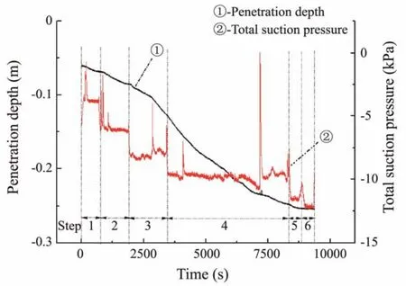
Fig.11 Time history of the penetration depth and total suction pressure.
3.4 Calculation of Penetration Resistance
The penetration resistance of N1, N2, and N3in the entire penetration process can be calculated using the penetration depth and the negative pressure value of each room,and the equation for the penetration resistance calculation is as follows:

whereFpis the penetration resistance,W'represents the submerged weight of CBF;siandAiare the measured negative pressure and the cross-section area of each room,respectively; andFbis the buoyancy of the submerged transition section.
Fig.12 shows the calculated results. The penetration resistance under conditions N1and N3are similar at each depth, while no law of penetration resistance as a function of penetration depth was observed under the N2condition.The curve may not be representative because it may be caused by an excessively large inclination during penetration or by uneven soil. Thus, the influence of eccentric load on penetration resistance is not observed. Such an absence is because this study only considers the eccentric load on the CBF under normal working conditions, which is relatively small in magnitude.
4 Influence of Seepage on Penetration Resistance Under Eccentric Load
4.1 Finite Element Model
A three-dimensional finite element model was established in accordance with the CBF model used in the test to investigate the influence of seepage on penetration resistance under eccentric load. The transition section was ignored to simplify the calculation. Fig.13 shows that the outer diameter of the bucket is 1 m, and the height of the wall and bulkhead is 0.28 m. The bucket is divided into seven rooms by bulkheads and internal skirts with a length of 0.25 m. The middle room is a regular hexagon that is larger than the six side rooms. As an elastic-plastic model based on the Mohr-Coulomb failure criterion, the soil diameter is 6 m with a height of 2.8 m, and the parameters are listed in Table 2. The element type of the bucket is C3D8R and the soil is C3D8P.
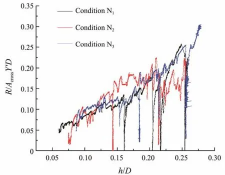
Fig.12 Penetration resistance of different eccentric load magnitudes.
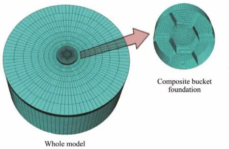
Fig.13 ABAQUS computational model.
The contact pair algorithm in the ABAQUS was employed to simulate the contact features of the interface between the foundation and the soil. In the calculation, different pore pressures were applied to the soil surface inside and outside the bucket to realize a transient simulation of the penetration process. The permeability coefficient of soil was 1 × 10⁻⁶m s-1, which was assumed to be a fixed value during the calculation process.
For analysis, the eccentric load can be offset by changing the negative pressure value of one room or three rooms,as shown in Fig.14. The offset room refers to the room where the absolute value of applied negative pressure in the penetration process is less than that of others to counteract the influence of eccentric load. The offset room in Fig.14(a)is Room #1, while the offset room in Fig.14(b)is Rooms #6, #1, and #2.
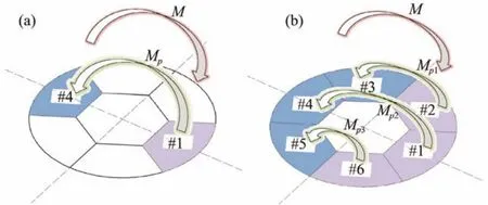
Fig.14 Schematic illustration of eccentric load offset strategy. (a), single room offset strategy; (b), triple room offset strategy.
Determining the negative pressure in each room under different conditions is necessary to perform different offset strategies in the numerical simulation. Fig.14(a)shows that the eccentric load is directly above Room #1, producing the bending momentMpresented in the figure.Reducing the negative pressure applied in Room #1 to produce the bending momentMp, which is generated by the negative pressure difference between Rooms #1 and#4, is necessary to counteract the influence of eccentric load. The negative pressure of the non-offset room during the numerical simulation process is the average value of the negative pressure of each room in the non-eccentric load penetration test. For example, the eccentric load is offset by changing the negative pressure value of one room, and the negative pressure of a non-offset room is 3.5 kPa when the penetration depthh/Dis 0.20, and the magnitude of the eccentric load is 80 N m. The following equations are obtained according to the force balance:

whereP4andP1are respectively the absolute values of negative pressure in Rooms #4 and #1, andS2is the distance between the centroid of Rooms #4 and #1, as shown in Fig.15.
The value ofP1can be determined in accordance with the above equations. the negative pressure of the non-offset room is also 3.5 kPa under the ‘triple room offset strategy’.To simplify the calculation,P6,P1, andP2are assumed to be equal, and the equations are as follows:
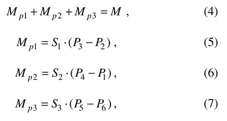
whereP1– P6are the negative pressure values of Rooms#1 to #6;S1,S2, andS3are shown in Fig.15.P6,P1, andP2can be solved by the equations above.
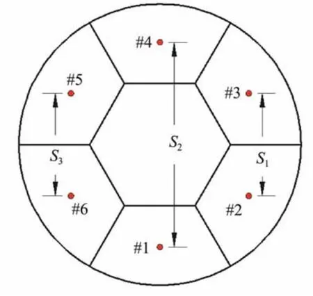
Fig.15 Distance between the centroid of different rooms represented by S1, S2, and S3.
Six conditions were set to investigate the influence of the seepage field under eccentric load. The suction installation process was simulated at different penetration depths in each test (h/D= 0.12, 0.16, 0.20, 0.24, and 0.28), and the variables in each test are listed in Table 4.
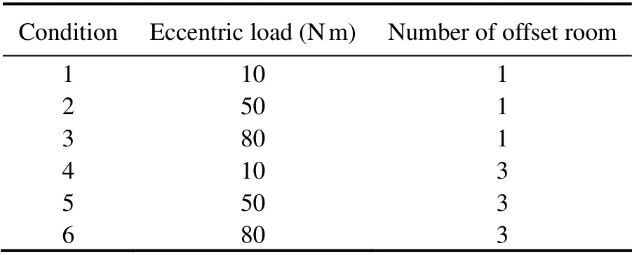
Table 4 Finite element calculation condition
4.2 Analysis of Seepage Field
Considering conditions 3 and 6, as representative examples to analyze the seepage field in the penetration process of CBF under penetration depthh/Dof 0.20, the negative pressure of the offset room is 1.382 kPa when the single room offset strategy is adopted after calculation,and the value becomes 2.440 kPa when the number of offset room is three. The negative pressure of the non-offset room is the average value of the negative pressure of each room in the non-eccentric load penetration test, which is 3.5 kPa. Fig.16 exhibits the excess pore pressure distribution corresponding to different offset strategies.
Different from the penetration process of CBF under uniform load, maintaining the same negative pressure in each room during penetration is impossible due to the influence of eccentric load and in order to control the inclination of the foundation during the sinking process. Thus,the effective stress at the same depth of the soil in each room is also different, which has a certain impact on the penetration resistance. Fig.16 demonstrates that the excess pore pressure of soil in each room slightly changes along the circular direction. Six points are selected along the circumferential direction at the tip of the bucket wall inside the offset room when the penetration depthh/Dis 0.20 under condition 6. Moreover, the values of excess pore pressure at each point are -715.123, -714.023, -713.504,-713.266, -713.51, and -714.041 Pa, which are almost equal in magnitude and are also true for other working conditions, depths, and positions. Therefore, the midpoint of the bucket wall of several typical rooms (Fig.17)was selected to extract the excess pore pressure along the depth direction under different conditions for comparative analysis. The result under condition 3, when the penetration depthh'is 0.20, is shown in Fig.18.
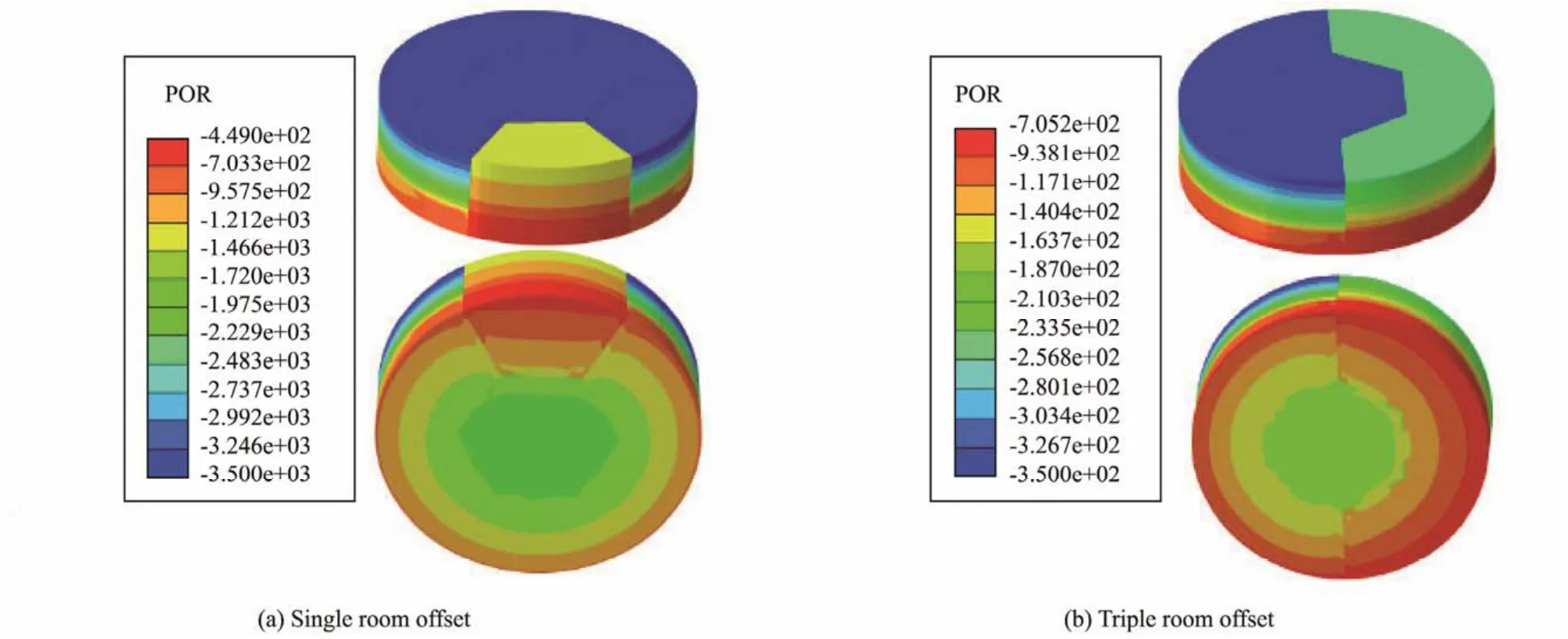
Fig.16 Distribution of excess pore pressure under different eccentric load offset strategies.
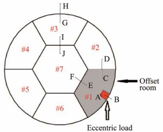
Fig.17 Typical points selected for excess pore pressure analysis.
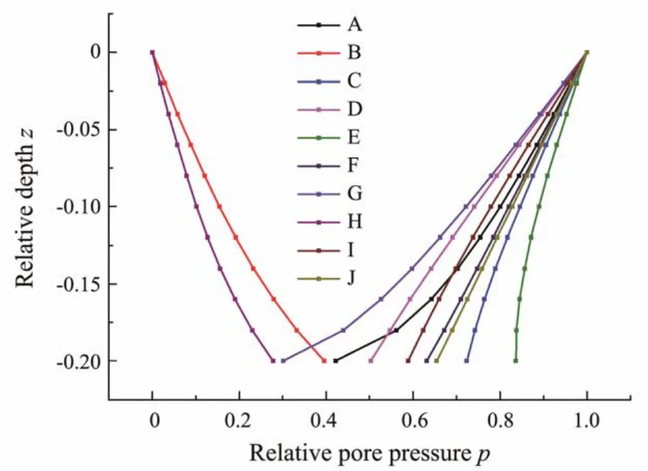
Fig.18 Normalized excess pore pressures along the depth of the bucket at different points.
The suction loss inside the bucket wall is defined asLin= 1 -p, while that outside the bucket wall is defined asLout=p. The figure illustrates that the excess pore pressure at each position changes almost linearly along the depth direction, while that when approaching the tip of the bucket wall is nonlinear. The comparative analysis of the excess pore pressure inside the bucket wall of the offset and nonoffset rooms (points A and G)indicates that the suction loss inside the bucket wall of the offset room is smaller than that of the non-offset room. Moreover, the negative pressure applied in the offset room is smaller than that in the non-offset room. Therefore, the capability of the soil to transfer negative pressure is limited. In a certain range, a large negative pressure value induces the transfer of a small relative value of negative pressure to the tip of the bucket wall, thus leading to a substantial suction loss. Similarly,the suction loss inside the offset room of the bulkhead is smaller than that inside the non-offset room.
4.3 Effect of Eccentric Load on Seepage Field and Penetration Resistance
Fig.19 shows the distribution of excess pore pressure along the depth direction of positions A and B at different penetration depths under condition 1. The figure demonstrates that the suction loss at the tip of the bucket is gradually larger than that at the surface inside the bucket under increased penetration depth. The values of excess pore pressure at the inner side of the bucket wall at position A (the offset room)under conditions 1, 2, and 3 are presented in Fig.20. This figure shows that the relative value of excess pore pressure under the same eccentric load gradually decreases with the increase in the penetration depth, and the suction loss continuously increases. The comparison of the curves of different magnitudes of eccentric loads indicates thatpchanges linearly when the load is small, gradually changes nonlinearly with the increase in eccentric load,and the slope of the curve increases with the absolute value ofz.
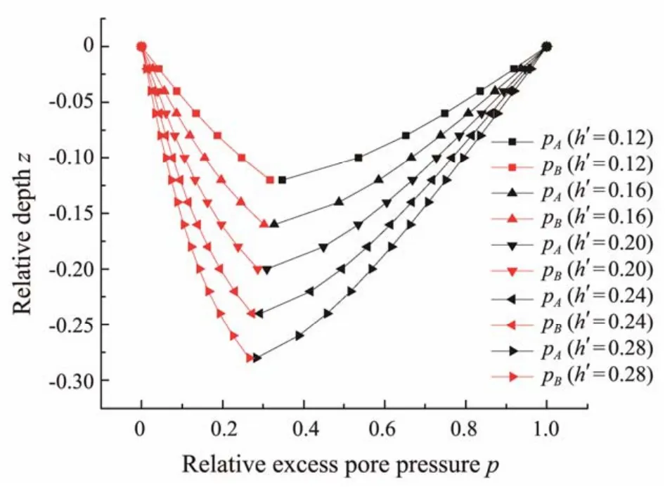
Fig.19 Distribution of excess pore pressure along the bucket depth with different penetration depth values.
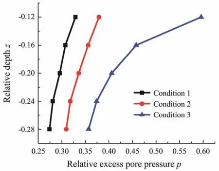
Fig.20 Distribution of excess pore pressure at the tip of the bucket at point A under different working conditions.
The following formula can be used to calculate the bucket penetration resistance in the sand under the absence of pore water flow according to API (2000), in which the pile foundation bearing capacity is mentioned as follows:
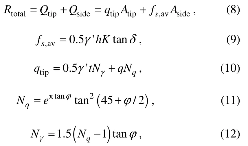
whereRtotalis the penetration resistance;Qtipdenotes the sum of the tip resistance;Qsideis the side friction of the bucket wall, internal skirts, and the bulkheads;qtipandfs,avare the tip resistance and side friction per unit area, respectively; andAtipdenotes the sum of tip areas of the penetrated bucket wall, internal skirt, and bulkheads, whileAsideis the sum of side areas of the penetrated bucket wall, internal skirt, and bulkheads.NqandNγdenote the bearing capacity factors of internal friction angleφ, andγ'is the effective unit weight of soil.tis the thickness of the bucket wall, internal skirts, and the bulkheads, andqrepresents the effective overburden pressure.Kis the ratio of the horizontal and vertical effective stress of the soil, andδis the friction angle between the soil and the bucket wall. The value ofKtan is 1.1 in this study (Andersenet al., 2008).
The influence of seepage on the penetration resistance of composite tubular foundations was analyzed under eccentric load based on the existing research. The following assumptions were established to simplify the calculation.
a)The suction loss varies linearly along with the depth of the bucket wall (Zhanget al., 2022);
b)Suction loss is equal at points along the circumferential direction at the same depth in the same room;
c)Only the influence of the seepage on the penetration resistance caused by the difference in negative pressure between the offset and adjacent side rooms and the middle room is considered, and the influence of the seepage between the offset and the opposite and alternate rooms is ignored (because it is negligible).
4.3.1 Calculation of penetrating resistance considering seepage
The effective stress at any depth of the soil isσ' = γ'zwhen the influence of seepage is disregarded. Seepage leads to the increase and decrease in the effective stress of the soil respectively outside and inside the bucket (Guoet al., 2017). Therefore, calculations of the effective stress of the soil on the outside and inside of the bucket wall considering the influence of seepage on the penetration resistance are as follows:

whereσoutandσinare the effective stresses outside and inside the bucket, respectively, andzis the depth.LoutandLinrepresent the suction loss at the corresponding positions (see Section 4.3),his the penetration depth, andsdenotes the applied negative pressure. Notably, under ideal conditions, the values of negative pressure of all non-offset rooms are equal, while that of the offset room is relatively small. For a simple calculation, the side friction of each non-offset room is considered equal. Therefore, the calculation formula of the side friction of the bucket wall considering the influence of seepage in the single room offset strategy is as follows:

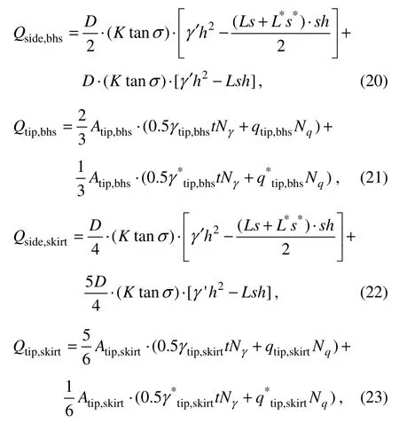
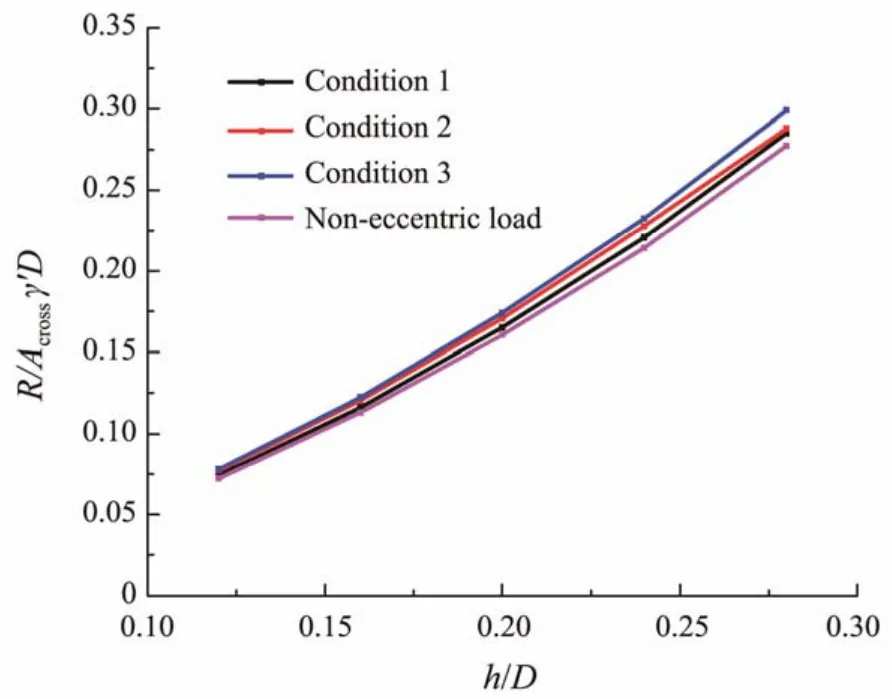
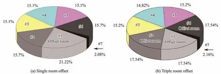
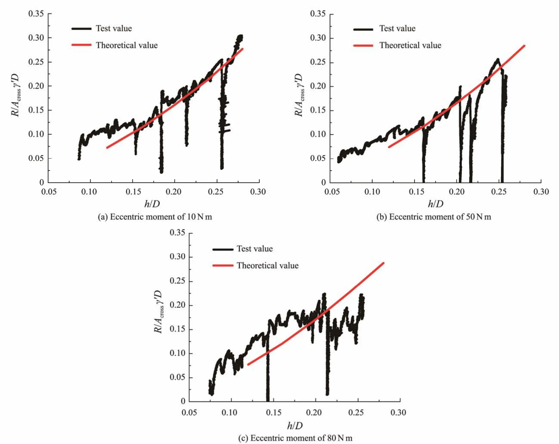
whereσ'andσ*'are the effective stress of offset and nonoffset rooms, respectively.t< whereLandL*are the suction loss of offset and non- offset rooms, respectively. While simultaneously reducing the side friction, the seepage also decreases the tip resistance to a certain extent. Under the action of seepage, the effective overburden of soilqwallat the end of the bucket wall can be estimated by using the following formula: Thus, the actual effective stress of the soilγwallat that point is: Referring to the analysis method of side friction, the end resistance of the bucket wall is divided into two parts,and the calculation formula of the tip resistance of the bucket wall is finally represented as follows: Similarly, the calculation formulas of side friction and tip resistance of the bulkheads and the internal skirts are represented as follows: whereQside,bhs,Qtip,bhs,Qside,skirt, andQtip,skirtrespectively denote the side friction of the bulkhead, the tip resistance of the bulkhead, the side friction of the internal skirt, and the tip resistance of the internal skirt. Therefore, the total penetration of the CBF is as follows: The penetration resistance under conditions 1, 2, and 3 was calculated and presented in Fig.21 according to Eq.(24), which was also compared with the penetration resistance without eccentricity. Fig.21 Comparison of calculated penetration resistance under different magnitudes of eccentric load. Fig.21 shows that the penetration resistance increases with the penetration of the bucket into the soil, and the relationship between the two is almost linear. When the bucket penetrates 0.28 m in the soil, the penetration resistance under conditions 1, 2, and 3 are 2237.17, 2260.89,and 2347.96 N, respectively. Moreover, the penetration resistance of the CBF without eccentric load is 2176 N.Thus, the eccentric load has a relatively minor effect on the penetration resistance. A high eccentric load leads to a slightly high penetration resistance. This condition is ascribed to the premise that the negative pressure applied to the offset room, wherein the eccentric load is located,should be less than that of other rooms to counteract the influence of the eccentric load. The decrease in the negative pressure inevitably increases the effective stress of the soil. Simultaneously, the seepage between the soil inside the offset room and that inside the adjacent room also leads to the enhancement in the effective stress, thereby increasing the penetration resistance. 4.3.2 Influence of number of offset rooms on seepage field and penetration resistance Based on the above-mentioned research, the penetration resistance of CBF was extended to the number of offset rooms of three, and the penetration resistance under conditions 4, 5, and 6 when the bucket penetrated 0.28 m in the soil was calculated and summarized in Table 5 and compared with conditions 1 – 3. The penetration of the triple offset room strategy is slightly larger than that of the single offset room strategy,but the difference between the values is small. Thus, the two offset strategies are feasible in practical engineering.With the increase in the penetration depth, the contact area between the wall and the soil increases, and the ratio of the side friction to the total resistance also rises. Herein,conditions 3 and 6 are considered representative examples to compare and analyze the ratio of each room under a penetration depthh'of 0.28 (see Fig.22). Comparative analysis indicates that the side friction of the offset room under conditions 3 and 6 is larger than that of the nonoffset room. No significant difference was observed in the penetration resistance, but the side friction proportion of each room changes with different eccentric load offset strategies. Under condition 3, the proportion of side friction of the offset room to total side friction is the largest,reaching 21.22%. The proportion of side friction of offset room to total side friction is 17.54% in condition 6, and that of the non-offset room is approximately 15%. The side friction of the internal skirt is only approximately 2%of the total side friction in the penetration process. Table 5 Comparison of penetration resistance under different offset strategies Fig.22 Ratio of side friction of each room under different offset strategies. The theoretical and experimental values of penetration resistance were compared on the basis of the above-mentioned research. Fig.23 shows that the experimental value under conditions 1 and 3 are in good agreement with the theoretical values, while a certain deviation exists between the experimental and test values under condition 2, which may be caused by excessive inclination or uneven soil during penetration. Simulating the seepage field under eccentric load and calculating the penetration resistance considering the seepage effect by using ABAQUS software is generally feasible. The penetration resistance of CBF under eccentric load was investigated in the current study based on a series of model tests and numerical simulations. The pore water pressure inside the offset room was compared, and the distribution of side friction of each room under different offset strategies was revealed. The main conclusions are summarized as follows. 1)The negative pressure of the offset room is smaller than that of other rooms when the negative pressure of CBF penetrates the soil under eccentric load due to the lower driving force required for sinking. 2)At the same penetration depth, the application of a large negative pressure value to the top of the bucket leads to a small relative value of negative pressure at the tip of the bucket and suction loss. 3)The penetration resistance of the foundation under eccentric load is larger than that without eccentricity. A large eccentric load induces a large penetration resistance.The penetration resistance of the CBF in this study increases by 2.81%, 3.90%, and 7.92% compared with that without eccentric load when the magnitude of the eccentric load is 10, 50, and 80 N m, respectively. 4)The influence of different eccentric load offset strategies on penetration resistance is negligible. In engineering practice, a reasonable eccentric load offset strategy can be selected in accordance with the actual situation. Undeniably, numerous systematic explorations are demanded to further study the influence of eccentric load on penetration resistance. Therefore, the suction penetration test and finite element simulation under the action of multiple groups of large eccentric loads should be conducted,and the formula between the penetration resistance and the eccentric load should also be deduced. Fig.23 Comparison of calculated and measured penetration resistance under different magnitudes of eccentric loads. Acknowledgement The authors would like to acknowledge the support from the National Natural Science Foundation of China (No.52171274).




4.4 Comparison of Test and Numerical Simulation Results
5 Conclusions
杂志排行
Journal of Ocean University of China的其它文章
- A Theoretical Model for the Microwave Emissivity of Rough Sea Surfaces
- Mechanism of Regional Subseasonal Precipitation in the Strongest and Weakest East Asian Summer Monsoon Subseasonal Variation Years
- Analytical and Experimental Studies on Wave Scattering by a Horizontal Perforated Plate at the Still Water Level
- Theoretical Prediction of the Bending Stiffness of Reinforced Thermoplastic Pipes Using a Homogenization Method
- Application of Converted Displacement for Modal Parameter Identification of Offshore Wind Turbines with High-Pile Foundation
- Time Domain Full Waveform Inversion Based on Gradient Preconditioning with an Angle-Dependent Weighting Factor
