Optimization of the cavity beam-position monitor system for the Shanghai soft X-ray free-electron laser user facility
2022-11-21JianChenYongBinLengLuYangYuLongWeiLaiRenXianYuan
Jian Chen· Yong-Bin Leng,2 · Lu-Yang Yu · Long-Wei Lai·Ren-Xian Yuan
Abstract To achieve high-efficiency operation of the highgain free-electron laser (FEL), the electron beams and radiated photon beams need to be overlapped precisely and pass through the entire undulator section. Therefore, a high-resolution beam-position monitor (BPM) is required.A cavity BPM (CBPM) with a resonant cavity structure was developed and used in the Shanghai Soft X-ray FEL(SXFEL)test facility and can achieve a position resolution of <1μm. The construction and operation of the SXFEL user facility also bring about higher requirements for beamposition measurement. In this case, the factors that affect the performance of the CBPM system were further analyzed. These included the amplitude and phase stability of the local oscillator, stability of the trigger signal, performance of the radio frequency front-end, signal processing electronics,and signal processing algorithms.Based on the upgrade and optimization of the system, a beam test platform was built at the end of the linear acceleration section of the SXFEL, and the experimental results show that the position resolution of the system can reach 177 nm at a bunch charge of 500 pC, and the dynamic range is controlled within ±300μm, and the relative measurement uncertainty of the bunch charge can reach 0.021%, which are significant improvements compared to the attributes of the previous system.
Keywords Cavity BPM · SXFEL · System optimization ·Position resolution · Measurement uncertainty · Algorithm
1 Introduction
High-gain free-electron laser (FEL) facilities based on linear accelerators are characterized by high brightness,full coherence, ultra-small spatial resolution, and ultra-fast temporal resolution. They have become an extremely important research apparatus to meet the demands of various frontiers, and basic scientific research has been developed worldwide [1]. The Shanghai Soft X-ray Free-Electron Laser(SXFEL),the first coherent X-ray FEL user facility in China, is divided into two phases: a test facility and a user facility. For the user facility, the beam energy can be accelerated to 1.6 GeV and the repetition rate can reach 50 Hz. The working schemes adopted include both self-amplified spontaneous emission (SASE) and external seed modes.The final goal is to build a high-brightness soft X-ray FEL source with wavelengths covering the ‘‘water window’ and supply light to the first five experimental stations [2, 3].
However, for high-gain FEL facilities, to reduce gain degradation, one of the key technologies deployed entails making the electron beams and radiated photon beams overlap tightly along a long undulator section. Because photon beams travel in a straight line, the electron beam position must be accurately aligned with the same straight line using high-resolution beam-position monitors (BPMs)[4]. Cavity BPMs (CBPMs), in which a resonant cavity structure is adopted and the characteristic modes excited by the electron beam are used to measure the beam parameters,have the advantage of high position resolution and are widely used in FEL facilities [5–7]. A CBPM was also applied to the SXFEL to measure the beam position.
Different types of CBPMs have been developed in several FEL facilities according to their working mode,and good experimental results have been obtained under normal operating conditions.A high quality factor(Q)X-band CBPM was designed at the Stanford Linear Accelerator Center for the Linac Coherent Light Source,and a position resolution of 200 nm at a bunch charge of 200 pC was obtained [8, 9]. A C-band low-Q CBPM with a resonant frequency of 4.76 GHz was designed for Super Photon ring–8 GeV.Its position resolution was 200 nm at a bunch charge of 300 pC, and the dynamic range is controlled within±300μm[10].In the European X-ray FEL,a low-Q CBPM for a multibunch working mechanism with a resonant frequency of 3.3 GHz was developed and combined with relevant electronics to achieve position resolutions of well below 1μm rms[11,12].For the Swiss FEL,two types of CBPM are used:The low-Q CBPM is used in the linear accelerator to easily separate two adjacent bunches of a 28-ns bunch spacing, and BPM pickups of the same basic structure, but with a higher Q value, are used in the undulators that receive only single bunches,which all have a position resolution of <1μm at the bunch charge from 10 to 200 pC [13]. In addition, the High Energy Accelerator Research Organization has also developed a rectangular CBPM [14] and a cylindrical CBPM [15] at Accelerator Test Facility 2. Under strict control of the beam emittance and beam jitter, position resolutions of 8.72 and 27 nm,respectively, were obtained.
In China, several institutes began independent CBPM research about ten years ago, and the first operational CBPM system was developed by the Shanghai Institute of Applied Physics and batch-processing was used in the SXFEL test facility [16]. The CBPM system consists mainly of a C-band cylindrical CBPM pickup, a radio frequency (RF) front-end that down-converts the RF to an intermediate frequency (IF) of ~500 MHz, and a digital BPM (DBPM) processor with an analog bandwidth of 500 ± 10 MHz.With a bunch charge of 500 pC,a position resolution of 880 nm and an uncertainty of relative bunch charge of 0.076% were obtained [17]. Although the resolution meets the requirement of <1μm,there are still many deficiencies in this measurement system,and results are far from the theoretical expectations.
To further optimize the performance of the system to meet the demands of the SXFEL user facility for a stable reference orbit, in this study, we analyzed the key factors that affect the performance of the CBPM system,including the cross talk between cavities, amplitude and phase stability of the local oscillator (LO), stability of the trigger signal,noise figure(NF)of the RF front-end,signal processing electronics, and signal processing algorithm.According to the analysis results,the system was upgraded and optimized, the beam test platform was built at the end of the linear accelerator for experimental verification, and the system performance was as expected. This laid the foundation for upgrading and optimizing the CBPM system for the SXFEL user facility and also provided technical background for the research, design, and construction of a CBPM system with higher position resolution requirements for the Shanghai High-repetition-rate XFEL and Extreme Light Facility.
2 System analysis and optimization
A typical schematic of the CBPM system is shown in Fig. 1. The system consists primarily of the following parts: a C-band CBPM pickup, an RF front-end, an LO, a DBPM processor (including algorithms), an external trigger and an external clock,and a signal transmission system such as a cable.
As briefly described in the Introduction, the main parameters of the CBPM system at the SXFEL test facility are summarized in Table 1.
To further optimize the system performance to meet the demands of the SXFEL user facility for a stable reference orbit, the impact on each subsystem was analyzed and optimized.
2.1 CBPM pickup
For a cylindrical RF cavity in a beam line,when a short bunch of charged particles passes through the cavity,it will excite electromagnetic oscillations resonant with the cavity. Because the electric field of a dipole mode, such as TM110, has an antisymmetric axis and linearly varies with the transverse offset near the cavity axis and the bunch charge, the amplitude of the beam-induced field strongly depends on the beam position and bunch charge.However,the electric field of a monopole mode, such as TM010, has axial symmetry at the cavity center. The amplitude is almost independent of the beam position and is sensitive only to the beam charge. In this case, the TM110cavity is available for beam-position measurements, and the TM010cavity provides a phase reference for the TM110signal, in addition to charge information [18–20].
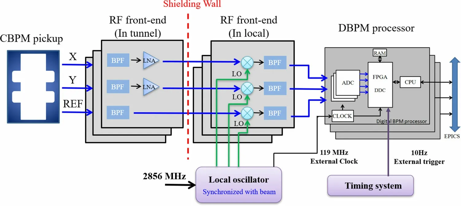
Fig. 1 (Color online) System schematic of the CBPM system
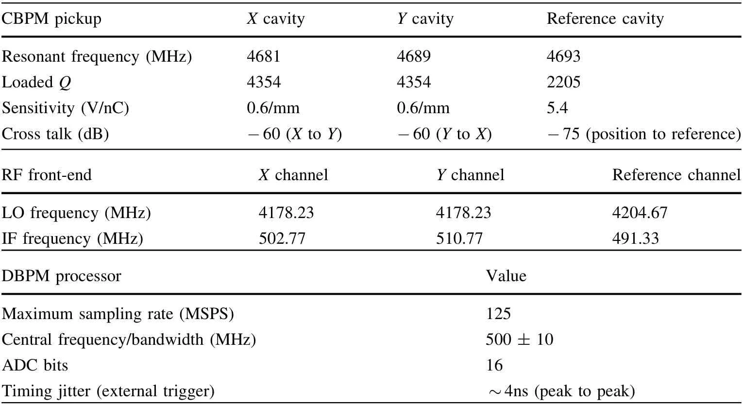
Table 1 Main parameters of the CBPM system at the SXFEL test facility
In designing the CBPM pickup, to reduce the impact of the cross talk between the cavities on the beam-position measurement[21],the resonant frequencies of the position cavities and the reference cavity are set to a slight deviation in the design and processing of the cavity pickup. The three-dimensional structure of the CBPM pickup is shown in Fig. 2.

Fig. 2 (Color online) Three-dimensional structure of the CBPM pickup
Compared with the SXFEL test facility, to simplify the complexity of the system, the frequency of the LO was designed as a single frequency,so that the frequency of the reference cavity was optimized from 4693 to 4683 MHz,thereby reducing the frequency difference of the IF signal.
The influence of machining accuracy on the cavity resonant frequency and Q value was investigated by testing several parts, and the reference and position cavities were processed independently and welded as a whole after their respective indicators met the requirements. A network analyzer was used to test the resonant frequency and Q value of the cavity before and after the final assembly welding to ensure consistency of the batch processing of the CBPM pickups. Figures 3, 4, and 5 show the cold test results for the resonant frequency,Q value consistency,andcross talk between the position cavities of the batch processing of 15 sets of CBPMs, respectively.
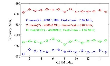
Fig.3 (Color online)Consistency of the resonant frequency of batchprocessed CBPM pickups

Fig. 4 (Color online) Consistency of the loaded Q value of batchprocessed CBPM pickups

Fig. 5 (Color online) Cross talk between position cavities of batchprocessed CBPM pickups
The cold test results show that the consistency of the cavity pickups improved significantly, the frequency difference between cavities could be controlled within±0.5MHz, the Q value consistency could be controlled within ±4%, and the cross talk between position cavities could be controlled to <-55dB.
2.2 RF front-end and LO
Owing to the limitation of analog-to-digital converters(ADCs),the RF front-end was used for the conditioning of the RF signal from the pickup to the low IF signal, and to generate an LO signal synchronized with the beam.
The NF of the RF front-end is one of the key factors affecting the performance of the system, and it has an approximately linear relationship with the amplitude extraction uncertainty of the IF signal. Therefore, the RF front-end was optimized based on the structure and performance of RF chips. A block diagram of the optimized RF front-end is shown in Fig. 6.It is divided into two parts:the preamplifier, located in the tunnel, and the cavity pickup, used to reduce the NF of the RF front-end. After testing, the NF was controlled to within 10 dB.
The LO is an important part of RF signal conditioning for the CBPM system, and its performance directly determines the amplitude and phase stability of the IF signal.The LO power jitter affects the power jitter of the IF signal.This was tested and evaluated in the laboratory based on the mixer at the RF front-end. As shown in Fig. 7, the influence of the LO power variation on the IF signal power was ~5%.
Figure 8 shows the simulation results of the effects of the LO signal phase stability on the measurements of the IF signal (based on the CBPM parameters of the SXFEL user facility).The simulation model is based on adding different degrees of phase and time jitter to the sinusoidal LO signal to simulate the LO phase jitter, and frequency mixing is based on multiplication of the RF and LO signals.
The simulation results show that the influence of the LO phase jitter on the amplitude extraction uncertainty of the IF signal is relatively minor; however, when the beam arrival time(BAM)is considered using the reference cavity of the CBPM, there are higher requirements for the LO phase jitter, which is approximately linear with the BAM measurement uncertainty.
Therefore, based on the results of the simulation and scheme of the CBPM system for the SXFEL test facility,the areas that can be optimized are as follows:
a. The structure of the multifrequency LO system through analog synthesis is complex,which will add additional phase noise. Based on the reference frequency of the SXFEL synchronization system (119 MHz/9 = 13.333 MHz), the LO can be optimized to a single frequency,thereby improving the amplitude and phase stability of the LO signal.

Fig. 6 (Color online) Block diagram of the optimized RF front-end for the SXFEL user facility
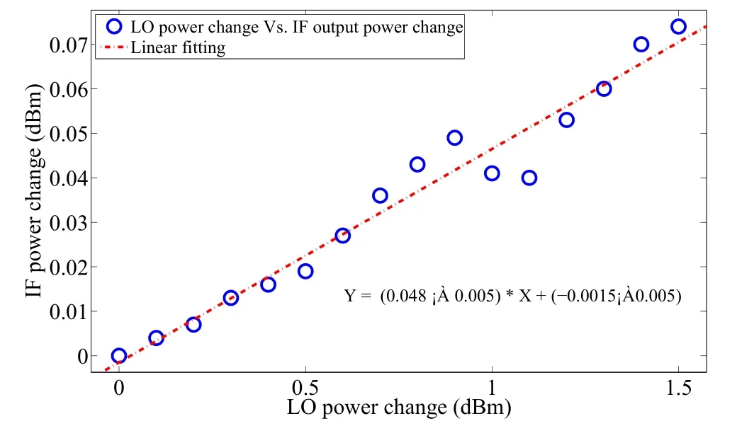
Fig. 7 (Color online) Test results of the influence of LO power variation on the IF signal
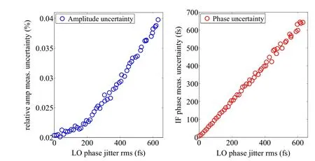
Fig. 8 (Color online) Simulation results of the effect of LO phase jitter on the amplitude and phase extraction uncertainty of the IF signal
b. The DBPM with an on-board front-end adds an additional NF. Moreover, the IF signal is limited to 500 ± 10 MHz by the narrowband filter of the DBPM,and bandpass undersampling (~500MHz IF with a sampling clock of 119 MSPS) cannot fully utilize the performance of the ADC.In view of the above, a single-frequency LO signal of 4654.22 MHz synchronized with the beam was designed,as shown in Fig. 9.
As tested by the signal analyzer (Agilent E5052A), the phase noise of 2856 MHz in the SXFEL user facility was~25.2 fs rms (10 Hz to 10 MHz), and the LO signal of 4654.2 MHz was ~29.3 fs rms.Therefore,the phase noise deterioration of the optimized LO system was ~15 fs rms,which can meet the requirements of beam position and BAM measurement.
2.3 DBPM processor
The relationship between the relative amplitude extraction uncertainty and the sampling rate of the data acquisition system under different bunch charges was simulated according to the parameters of the cavity pickup and RF front-end. In the simulation, for a specific IF signal, if the sampling rate of the ADC is changed,the effective number of bits(ENOB)of the ADC also changes.An investigation of commercial mainstream ADC chips [22] revealed that there is a relatively close relationship between the ENOB and Fs of the ADC (10–100 MHz input), as shown in Fig. 10.
Therefore, the relationship between Fs and ENOB can be approximately expressed by

The relationship between the ENOB and signal-to-noise ratio (SNR) of the ADC is expressed as
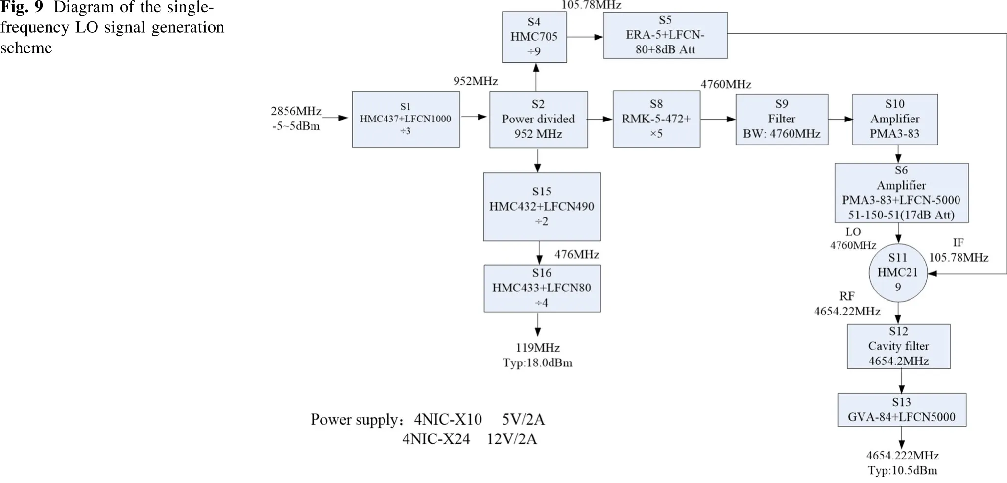
Fig. 9 Diagram of the singlefrequency LO signal generation scheme

Fig. 10 Relationship between the sampling rate and the ENOB of commercial mainstream ADCs

where Ts is in seconds and Nadc is in volts. k1and b1can be obtained by linear fitting, as shown in Fig. 10.

Fig. 11 Relationship between the relative amplitude extraction uncertainty and the sampling rate of the data acquisition system under different bunch charges
Therefore, the simulation model was constructed by adding noise based on the relationship between the ADC sampling rate and the ENOB. The simulation results are shown in Fig. 11.It can be seen that,in the case of a large bunch charge or a high SNR of the RF signal,an ADC with a lower sampling rate but a higher effective bit is more advantageous. Conversely, in the case of a small bunch charge or a low SNR of the RF signal, the quantization error of the ADC is no longer the main limitation, and higher sampling rates can yield more sampling points for averaging to obtain greater signal-processing gain.

Fig. 12 Hardware diagram of the upgraded DBPM
Based on the DBPM processor developed for the Shanghai Synchrotron Radiation Facility and the SXFEL test facility [23–27], the maximum sampling rate was 125 MSPS. Although the processor does not achieve the best performance at a bunch charge of 500 pC,the deterioration in performance was not substantial. Therefore, the DBPM can still be optimized.The onboard front-end was removed to reduce the additional NF, the analog bandwidth was expanded to 650 MHz, and the ADC performance was improved with an IF of ~30 MHz instead of bandpass undersampling. The hardware diagram of the upgraded DBPM is shown in Fig. 12. It is composed of four modules: the ADC board, a digital motherboard, an advanced RISC machine board, and a power module.
2.4 Timing jitter
For the CBPM system to realize synchronous acquisition of signals, it is necessary to provide a stable external trigger synchronized with the machine reference clock.However, trigger jitter has a significant influence on the extraction of the IF signal phase,including judgment of the beam offset direction and measurement of the BAM.
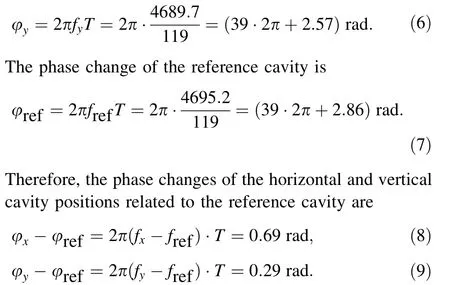
To evaluate the influence of the trigger jitter on the phase extraction of the IF signal,a CBPM signal(X:4682.1 MHz, Y: 4689.7 MHz, and reference: 4695.2 MHz) was selected to construct the waveform when the trigger was jittered at a factor of ±2 greater than the ADC sampling clock period,as shown in Fig. 13.The phase change in the position of the cavities relative to the reference cavity was also calculated, and the simulation results are shown in Fig. 14.
It can be seen from the simulation results that, for the selected CBPM frequency and DBPM parameters with a sampling rate of 119 MHz,when the trigger jitter is greater than one ADC sampling clock period, the phase distribution of the position cavities relative to the reference cavity will generate a fixed offset. This offset is related to the cavity frequency and ADC sampling rate, which can be explained by the equations that follow.
When the trigger jitter is at one sampling clock period,the phase change in the horizontal position cavity is

The phase change in the vertical position cavity is

Fig. 13 Construction of waveforms with trigger jitter
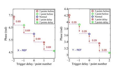
Fig.14 Phase change of the position cavities relative to the reference cavity with trigger jitter
It can be seen from the above analysis that the difference frequency design of X, Y, and reference cavities significantly reduces the influence of cross talk between cavities.Meanwhile, the disadvantage is that the requirements for external trigger jitter also become significantly more stringent.As the sampling frequency of the ADC increases,the requirements for trigger jitter also increase.

Fig. 15 (Color online)Waveform and phase distribution with the external trigger jitter and optimized results after using the internal trigger phase-locking algorithm
Given the upgrades of the CBPM system, there are two main areas for optimization. The first is to optimize the timing system in the hardware to reduce jitter and the deterioration of signal distribution and transmission, but the workload is large and difficult to achieve. The other is to optimize the algorithm, combine the internal trigger function, and introduce an algorithm to align the peak points of the waveform. The algorithm would set the peak alignment point, and, after each new set of data is collected, the peak point in the time domain would be set for alignment. This would achieve the function of phaselocking based on the internal trigger. This algorithm can easily realize real-time processing in a field-programmable gate array (FPGA), and is no longer limited by the timing system, which greatly improves the stability of the system and also solves the problem of accurate phase extraction of the BAM system. Therefore, it was adopted.
Figure 15 shows the waveform and phase distribution of the IF signal of the reference cavity when the external trigger jitter is greater than one ADC sampling period and compares the results after using the internal trigger phase-locking algorithm,which fully verifies the practicability of this algorithm.
2.5 Digital signal processing algorithm
Using a fast Fourier transform is a signal processing method in the frequency domain that is often used in CBPM signal processing. The amplitude and phase of the resonant frequency point carry the position and offset direction information of the electron beam, which has the characteristics of high efficiency and can easily realize real-time signal processing in the FPGA;therefore,the fast Fourier transform was also used in the CBPM system at the SXFEL facility.

Fig.16 a Difference in the index of peak points caused by the fence effect. b Phase distribution of the IF signal resulting from the difference in the index of peak points (resonant frequency of the cavity pickup)
The signal of the CBPM is a typical sinusoidal oscillation signal with an exponential decay. The SNR of the damped signal decays as the signal length increases.However,the signal processing gain increases as the signal length increases. Therefore, there is a balance between the noise-to-signal and signal-processing gains, which minimizes the amplitude and phase-extraction uncertainty.According to the theoretical analysis and simulation in Chen et al.[28],the optimal signal processing window is a factor of 1.257 greater than the decay time and is irrelevant to other parameters of the system.This window can be used for accurate signal amplitude and phase extraction.
For ADCs with a limited sampling rate, combined with the best data processing window, the number of sampling points for data processing is small, and the frequency domain resolution is insufficient, because of the influence of the fence effect and noise,which will cause the index of the peak points(corresponding to the resonant frequency of the cavity pickup) of different sample data to be slightly different.Consequently,there is a large calculation error in the extraction of the phase, as shown in Fig. 16.
In theory, once the resonant frequency of the cavity pickup is determined, the spectral peak point of the IF signal can be determined (corresponding to the resonant frequency of the cavity pickup). Given the insufficient FPGA resources in the DBPM, the method of fixed frequency (in which the preset fixed frequency point is input in the algorithm) was used to extract the amplitude and phase information of the IF signal. The advantages of this method are that it is simple to implement in an FPGA and consumes fewer FPGA resources. For the samples in Fig. 16, after optimization using the fixed-frequency algorithm, the extracted phase distribution is shown in Fig. 17.
3 Beam experiment
According to the above analysis of the factors that affect system performance, the measurement system for the SXFEL user facility was upgraded and optimized. A beam test platform with three adjacent CBPM pickups was built inside the drift section at the end of the linear accelerator of the SXFEL to evaluate the performance of the system.Figure 18 shows a diagram of the geometrical distribution and association analysis of pickups.

Fig.17 Phase distribution of IF signal after being optimized by using the fixed frequency algorithm

Fig. 18 Diagram of the geometrical distribution and association analysis of the pickups
By using the geometric relationships in

the position reading of CBPM2(U′2)can be estimated using the position readings of CBPM1 and CBPM3 (U1and U3,respectively). In addition, the position reading of CBPM2 can be obtained by itself (U2). To calculate the difference between U2and U′2(ΔU) under the assumption that all BPMs have equal position jitter,the position resolution can be calculated using

Combined with the online position calibration factor,shown in Fig. 19, the residual distribution between the measured and expected values of the CBPM2 is shown in Fig. 20.In addition,two adjacent CBPM reference cavities were used to remove the influence of the jitter of the bunch charge to evaluate the performance of the bunch charge measurement. The evaluation results for the relative measurement uncertainty of the bunch charge are shown in Fig. 21.
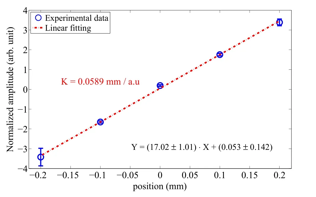
Fig. 19 Position calibration factor of the system
It can be seen from the experimental results that the position resolution of the system can reach 177 nm at a bunch charge of 500 pC, and the dynamic range is controlled within ±300μm, and the relative measurement uncertainty of the bunch charge can reach 0.021%, which are significant improvements compared to the attributes of the previous system.
4 Conclusion
The key factors that affect the performance of the CBPM system(e.g.,cross talk between cavities,amplitude and phase stability of the LO,stability of the trigger signal,NF of the RF front-end, signal processing electronics, and signal processing algorithm) have been analyzed, and optimization methods for each part have been proposed.The performance evaluation of the upgraded system was also performed on the beam test platform, where the position resolution of the system reached 177 nm at a bunch charge of 500 pC, and the dynamic range is controlled within ±300μm, and the relative measurement uncertainty of the bunch charge reached 0.021%. The optimized CBPM system was applied to the SXFEL user facility in batches, and its performance was greatly improved.
5 Future work
The stability of the system is another important factor that must be considered in the project. The externally affected parameters of a typical CBPM system include external trigger signals related to the timing system,and an algorithm has been used to realize the function of internal trigger phase-locking, which does not depend on the jitter and drift of the external timing signal.
Another parameter is the machine reference clock(input of the LO signal) related to the synchronization system.The next step is to achieve independence of the whole system without using the machine reference clock as the source of the LO signal. For example, an explorable direction is to use the dual-cavity mixing scheme for the position and reference cavity signals.
Author contributionsAll authors contributed to the study conception and design. Material preparation, data collection and analysis were performed by Jian Chen, Yong-Bin Leng, Lu-Yang Yu, Long-Wei Lai and Ren-Xian Yuan. The first draft of the manuscript was written by Jian Chen and all authors commented on previous versions of the manuscript.All authors read and approved the final manuscript.
杂志排行

Nuclear Science and Techniques的其它文章
- Thermal hydraulic characteristics of helical coil once-through steam generator under ocean conditions
- Lifetime estimation of IGBT module using square-wave loss discretization and power cycling test
- A beam range monitor based on scintillator and multi-pixel photon counter arrays for heavy ions therapy
- Research on manufacture technology of spherical fuel elements by dry-bag isostatic pressing
- Beam–beam effects and mitigation in a future proton–proton collider
- Ultrahigh accelerating gradient and quality factor of CEPC 650 MHz superconducting radio-frequency cavity