Ultrahigh accelerating gradient and quality factor of CEPC 650 MHz superconducting radio-frequency cavity
2022-11-21PengShaWeiMinPanSongJinJiYuanZhaiZhengHuiMiBaiQiLiuChaoDongFeiSiHeRuiGeLiangRuiSunShiAoZhengLingXiYe
Peng Sha· Wei-Min Pan · Song Jin · Ji-Yuan Zhai ·Zheng-Hui Mi · Bai-Qi Liu · Chao Dong· Fei-Si He·Rui Ge· Liang-Rui Sun · Shi-Ao Zheng · Ling-Xi Ye
Abstract Two 650 MHz single-cell superconducting radio-frequency (SRF) cavities used for the Circular Electron Positron Collider(CEPC)were studied to achieve a high accelerating gradient(Eacc)and high intrinsic quality factor (Q0). The 650 MHz single-cell cavities were subjected to a combination of buffered chemical polishing(BCP) and electropolishing (EP), and their Eacc exceeded 40 MV/m. Such a high Eacc may result from the cold EP with more uniform removal. BCP is easy, cheap, and rough, whereas EP is complicated, expensive, and precise.Therefore, the combination of BCP and EP investigated in this study is suitable for surface treatments of mass SRF cavities. Medium temperature (mid-T) furnace baking was also conducted, which demonstrated an ultrahigh Q0 of 8 × 10¹⁰ at 22 MV/m for both cavities, and an extremely low BCS resistance (RBCS) of ~1.0 nΩ was achieved at 2.0 K.
Keywords SRF cavity · Accelerating gradient · Quality factor · Electropolishing · Vertical test
1 Introduction
Superconducting radio-frequency (SRF) cavities are widely used in modern particle accelerators [1], including high-energy colliders [2, 3], synchrotron light sources [4],free electron lasers [5–7], and proton/neutron sources[8–12]. SRF cavities made of niobium, which has a high residual resistance ratio (RRR), and exhibiting a high accelerating gradient(Eacc)and high intrinsic quality factor(Q0) are required for such accelerators. Therefore, many technologies and approaches have been studied to improve the Eaccand Q0of SRF cavities; these approaches include the International Linear Collider (ILC) recipe, nitrogen doping, and mid-T baking [13–17]. The electropolishing(EP) technique has been developed into a standard treatment for the 1.3 GHz 9-cell cavity for the ILC and is known as ‘‘the ILC recipe’’. The maximum Eaccof 1.3 GHz 9-cell cavities achieved using the ILC recipe exceeds 40 MV/m, which is remarkably high for SRF cavities[5,18,19].The 2/0 recipe(two minutes of nitrogen exposure followed by zero minutes of annealing at 800 °C in a furnace) was used for the nitrogen doping of 1.3 GHz 9-cell cavities for the Linac Coherent Light Source II High Energy.Consequently,the Q0of the cavities was improved to 3.0 × 10¹⁰at 21 MV/m, which is higher than the specification of the Linac Coherent Light Source II(2.7 × 10¹⁰at 16 MV/m)[20].Moreover,following mid-T furnace baking, the Q0of 1.3 GHz 9-cell cavities reached 3.8 × 10¹⁰at 16 MV/m on average at the Institute of High Energy Physics (IHEP), Chinese Academy of Sciences[21]. Thus, exceptionally high Eaccand Q0have been achieved for the 1.3 GHz 9-cell cavities.
The Circular Electron Positron Collider (CEPC), which was proposed by the IHEP in 2012, is a 100-km collider with a center-of-mass energy of 90–240 GeV for Z,W,and Higgs bosons [22]. Precise measurements of the Higgs boson are considered critical for developments in highenergy physics. The CEPC is capable of producing 1,000,000 Higgs bosons within 10 years and is regarded as a Higgs factory. The SRF system of the CEPC is critical and challenging owing to the wide range of beam energies and currents [23]. The booster ring of CEPC adopts 1.3 GHz 9-cell cavities, as well as E-XFEL and ILC. The collider ring of the CEPC adopts hundreds of 650 MHz SRF cavities operated in the continuous wave (CW) mode[24], which compensate for the loss of beam energy resulting from synchrotron radiation. Large elliptical(<1 GHz)cavities with high Eaccand Q0have been widely adopted for accelerator applications, such as in the European Spallation Source (ESS) [8], Facility Rare Isotope Beams (FRIB) [9], Spallation Neutron Source (SNS) [10],Proton Improvement Plan II(PIP-II)[12],Beijing Electron Positron Collider II(BEPC II)[25],and the China initiative Accelerator Driven System (CiADS) [26]. However, they have not been studied as extensively as 1.3 GHz cavities.The operation specification of 805 MHz cavities with β = 0.81 for SNS is 5.0 × 10⁹@ 15.8 MV/m at 2.1 K[10], whereas the operation specification of 704.42 MHz cavities with β = 0.86 for ESS is 5.0 × 10⁹@19.9 MV/m at 2.0 K[27].The 650 MHz cavities with β = 0.92 for PIPII require a Q0of 3.0 × 10¹⁰at 18.8 MV/m (at 2.0 K),which indicates a requirement of a higher Q0than that required for ESS and SNS [12]. Finally, the 650 MHz cavities with β = 1 for CEPC require a Q0of 4 × 10¹⁰at 22 MV/m during the vertical test (VT) at 2.0 K; these specifications are difficult to realize compared with those of other cavities.
In the past, large elliptical cavities were mostly processed using buffered chemical polishing (BCP), which met the specifications for projects such as ESS and SNS.BCP is more convenient and simpler than EP. However,the surface roughness of SRF cavities processed by BCP is almost an order of magnitude higher than that processed by EP; thus, achieving high Eaccby BCP is difficult [28–30].Hence, cavities processed by BCP could not consistently exceed the specifications of the 650 MHz cavities for PIPII and CEPC,whereas those processed by EP could achieve higher Eaccand Q0. After the EP process, the 650 MHz single-cell cavity of PIP-II reached a maximum Eaccof ~37 MV/m at the Fermi National Accelerator Laboratory (FNAL), which is an ultrahigh value for large elliptical cavities [12]. However, EP is complicated to perform and is expensive. Thus, the combination of BCP and EP may be efficient and convenient for large elliptical cavities with high Eaccand Q0. Therefore, validating the‘‘BCP + EP’’ recipe for 650 MHz cavities is of considerable interest for our research. In our study, two 650 MHz single-cell cavities for CEPC were processed by BCP and EP, both of which exceeded the Eaccof 40 MV/m.
The remainder of this paper is organized as follows.Section 2 briefly describes the materials used, fabrication,BCP process, and vertical test results of 650 MHz singlecell cavities. Section 3 describes the 1st EP process and discusses the performance of the 650 MHz single-cell cavities. Section 4 describes the mid-T furnace baking implemented after the 1st EP process. The 2nd EP process(cold EP)and the performance of the cavities are discussed in detail in Sect. 5. Finally, the conclusions of this study are presented in Sect. 6.
2 BCP process
The two 650 MHz single-cell cavities, 650S4 and 650S5, investigated in this study, were made of fine-grain niobium, except for the flanges made of niobium–titanium(NbTi) alloy. The main parameters of the fine-grain niobium are listed in Table 1. The cavity components were formed by deep drawing and joined by electron beam welding. After fabrication, 650S4 and 650S5 were subjected to the same surface treatments, i.e., bulk BCP(~200 μm), high-temperature annealing at 800 °C for 3 h, and light BCP (~30 μm), all of which were conducted at Ningxia Orient Superconductor Technology Co.,Ltd. (OSTEC). A mixture of hydrofluoric acid (HF), nitric acid (HNO3), and orthophosphoric acid (H3PO4) in a ratio of 1:1:2 was adopted for the BCP process. Then, the cavities were transferred to the IHEP, where a high-pressurewater rinse (HPR), an assembly with flanges in a cleanroom, and low-temperature baking (120 °C for 48 h) were performed. Uniform low-temperature baking was performed using a heating jacket, as shown in Fig. 1. Subsequently, vertical tests were conducted, as shown in Fig. 2.The residual magnetic field around the cavity was less than 5 mGs because of magnetic shielding inside the dewar[31, 32]. During the vertical tests, 650S4 and 650S5 were both quenched below an accelerating gradient of 25 MV/m,as shown in Fig. 3,along with a strong field emission.The accelerating voltage (VC= Eacc× 0.23) and surface peak RF magnetic field (Bpeak) as well as Eaccare adopted as scales of the RF field in Fig. 3. For 650S4 and 650S5, the relation between Bpeakand Eaccis expressed as follows:Bpeak/Eacc≈4.2 mT/(MV/m). Thus, the Q0values of 650S4 and 650S5 were both lower than the CEPC VT specification of 4 × 10¹⁰at 22 MV/m. Subsequently,650S4 and 650S5 were subjected to the EP process.

Table 1 Main parameters of fine-grain niobium
3 1st EP process
The EP was performed at the OSTEC,too.The setup of the EP process for the 650 MHz single-cell cavity is depicted in Fig. 4.The electrolyte for the EP process was a mixture of HF and H2SO4at a ratio of 1:9. Various acid flow rates were investigated in this study. Finally, a flow rate of 15 L/min was used.A nominal voltage of 21 V was adopted for the EP process. First, 650S5 was subjected to EP, and its inner surface was removed by ~215 μm at <25 °C and ~100 μm at ~17.5 °C. Next, the surface of 650S4 was removed by ~20 μm by light EP at ~25 °C, followed by high-temperature annealing at 950 °C for 3 h; subsequently, another removal of ~20 μm by light EP at ~17.5 °C was performed again. The details are introduced in [24]. Subsequently, 650S4 and 650S5 were shipped to the IHEP,where the HPR,assembly with flanges, low-temperature baking (120 °C for 48 h),and vertical tests were conducted. Higher Eaccand Q0values were observed after the EP process, as shown in Fig. 3. 650S4 quenched at ~35.0 MV/m with a Q0of 2.7 × 10¹⁰, whereas 650S5 quenched at ~37.5 MV/m with a Q0of 1.4 × 10¹⁰. The combination of BCP and EP was effective for achieving a high Eaccand Q0[13].Hence,bulk EP in the ILC recipe may be replaced by bulk BCP,which is favorable mass production and surface treatments of SRF cavities. In addition, the Q0of 650S5 was slightly lower than that of 650S4 at a high gradient (>20 MV/m),which may be because it was not subjected to high-temperature annealing [24]. Annealing can degas hydrogen trapped in niobium, thereby reducing the RF loss and increasing Q0of the SRF cavity [33].

Fig. 1 (Color online) Low-temperature baking of 650 MHz singlecell cavity
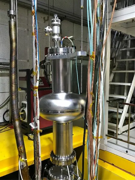
Fig. 2 (Color online) Site photograph of vertical test of 650 MHz single-cell cavity

Fig.3 (Color online)Vertical test results of 650S4 and 650S5,which demonstrate Q0 and radiation versus accelerating gradient

Fig. 4 (Color online) Setup of EP process of 650 MHz single-cell cavity
Subsequently, 650S5 was again subjected to high-temperature annealing at 900 °C for 3 h, which was aimed at hydrogen degassing. Next, the 650 MHz single-cell cavities were transferred to an ISO 6 cleanroom.The inner and outer surfaces of the cavities were manually rinsed with Liquinox solution (2%), followed by HPR, and then dried in the cleanroom.
4 Mid-T furnace baking
Following drying,the 650 MHz single-cell cavities were transferred to a furnace for mid-T baking. The recipe of baking at 300 °C for 3 h and 1.3 GHz cavities used in reference [21] were used. During the entire process, the cavities were supported by two niobium holders. The flanges of the cavities were covered with niobium foils, as shown in Fig. 5a, and were freshly polished chemically to prevent particles from entering the interior space of the cavities during the baking process. The vacuum and temperature curves during the mid-T furnace baking of 650S4 are shown in Fig. 5b. Prior to heating, the furnace was evacuated to an ultrahigh vacuum (<5 × 10⁻⁶Pa) using two cryopumps. The peak pressure reached ~2.3 × 10⁻⁵Pa during the baking process.When the temperature dropped to ~50 °C, the pressure decreased to ~2.1 × 10⁻⁶Pa, and the cavity was removed from the furnace. The mid-T furnace baking of 650S5 was identical to that of 650S4.
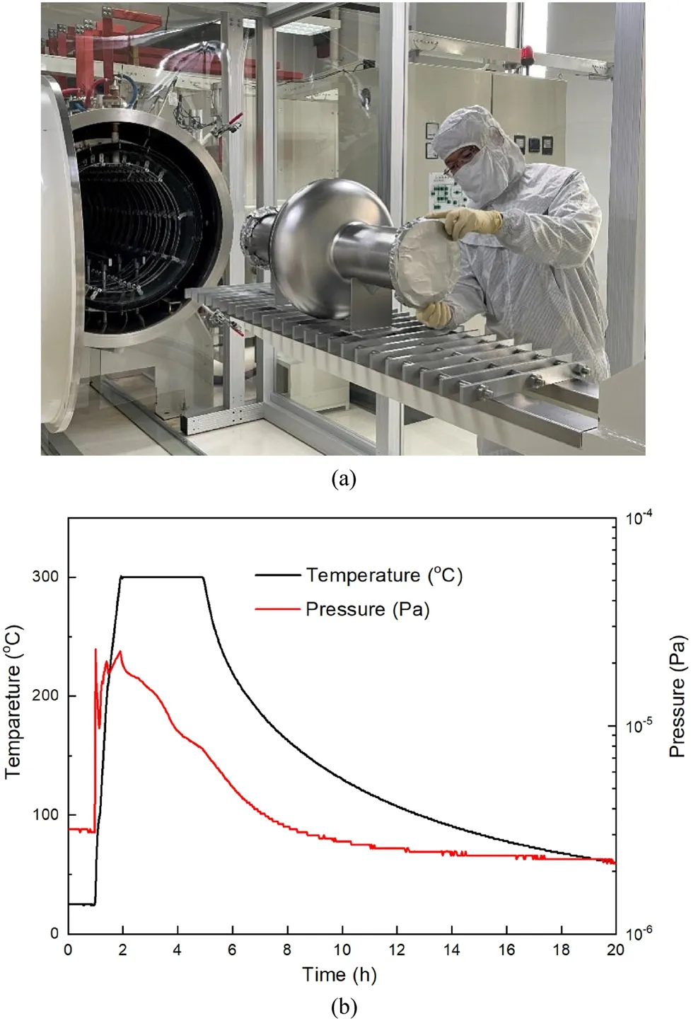
Fig. 5 (Color online) Mid-T furnace baking of 650 MHz sing-cell cavity. a Setup of mid-T furnace baking for 650 MHz single-cell cavity with flanges covered by niobium foils; b vacuum and temperature curves during mid-T furnace baking of 650S4
Following mid-T furnace baking, 650S4 and 650S5 were subjected to HPR, clean assembly with flanges, and vertical tests; low-temperature baking was not performed.The curves of Q0versus Eaccduring the vertical tests are shown in Fig. 3. Both cavities demonstrated significantly high Q0values for all the RF fields. The Q0values of 650S4 and 650S5 exceeded 8.0 × 10¹⁰at 22 MV/m,which was twice that of the CEPC VT specification(4.0 × 10¹⁰).650S5 achieved a high Q0of 6.4 × 10¹⁰at 30 MV/m,which was a relatively high Eaccat this frequency.No field emissions were observed during the vertical tests of the 650S4 and 650S5. In addition, neither of the 650 MHz single-cell cavities demonstrated the anti-Q-slope behavior,which is typically observed in 1.3 GHz cavities subjected to mid-T baking [16, 17, 21]. Finally, 650S4 and 650S5 quenched at ~24.2 MV/m and ~31.2 MV/m, respectively.Thus,the maximum Eaccof the 650 MHz single-cell cavities subjected to mid-T furnace baking decreased substantially. In other words, mid-T furnace baking could increase the Q0of 650 MHz cavities but lowered the Eacc.
For the RF cavity,Q0is defined as Q0= G/RS,where G denotes the geometric factor, and RSdenotes the surface resistance. For 650S4 and 650S5, G is 284 Ω. Hence, the Q0of 650 MHz single-cell cavities was enhanced after mid-T furnace baking, indicating a reduction in RS. RSconsists of two parts: temperature-dependent resistance(RBCS) and temperature-independent resistance (Rres)[33–35].

The first term in the equation is RBCS,which depends on the Boltzmann constant (k), temperature (T), resonant frequency of the SRF cavity (f), energy gap of the superconductor (2Δ), and the fitting constant (A). A depends on material parameters.
For the investigations of RBCSand Rres, 650S4 was subjected to vertical tests at different temperatures below 2.0 K.The RBCSat 2.0 K and Rresof 650S4 was calculated using Eq. (1), as shown in Fig. 6. The values were compared with those of the 1.3 GHz nine-cell cavity (N8),which was subjected to the EP process and mid-T furnace baking at 300 °C for 3 h [21]. The RBCSof 650S4 was ~1 nΩ and remained constant as a function of Eaccand Bpeak, similar to that of 650 MHz single-cell cavities subjected to nitrogen doping at FNAL [12]. The decrease in RBCSas a function of the RF field for N8 was not reproduced for 650S4. It was observed that mid-T furnace baking and nitrogen doping could not reverse the RBCSat the frequency of 650 MHz [12]. Therefore, the anti-Qslope behavior could not be achieved for the 650 MHz cavity subjected to mid-T furnace baking. Therefore, the RF field dependence of RBCSwas correlated with the resonant frequency of the SRF cavity, which has been explained in detail in [34–36]. Furthermore, Rresincreased gradually to ~2 nΩ with the RF field.
5 2nd EP process (cold EP)
Subsequently, 650S4 and 650S5 were subjected to 30 μm EP, aiming to eliminate mid-T furnace baking and reset the inner surface. The temperature for this 2nd EP was lower than that of the 1st EP and was maintained below ~13 °C;thus,it was called‘cold EP’’.Recently,it was found that cold EP could achieve uniform removal of a 1.3 GHz cavity, thereby improving the quench field[37, 38].
For 650 MHz single-cell cavities,the surface removal at the beam tubes,irises,and equators,represented by Nos.1–6 in Fig. 7a, was measured during the EP process. Figure 7b presents the results of the 1st EP for 650S4, which indicate that the removal at the equators(3,4)was less than that at the beam tubes(1,6).Figure 7c shows the results of the 2nd EP for 650S4,which demonstrate that the removal at the equators (3, 4) was almost the same as that at the beam tubes (1, 6). Therefore, the cold EP could successfully achieve uniform removal of the 650 MHz cavities as well as the 1.3 GHz cavity.
After the 2nd EP process, the inner surfaces of 650S4 and 650S5 were examined.There were no apparent defects in either of the cavities. The surface of 650S4 was similar before and after the 2nd EP,as shown in Fig. 8.Both of the 650 MHz single-cell cavities were subsequently subjected to HPR, clean assembly with flanges,and low-temperature baking at 120 °C for 48 h, followed by vertical tests.
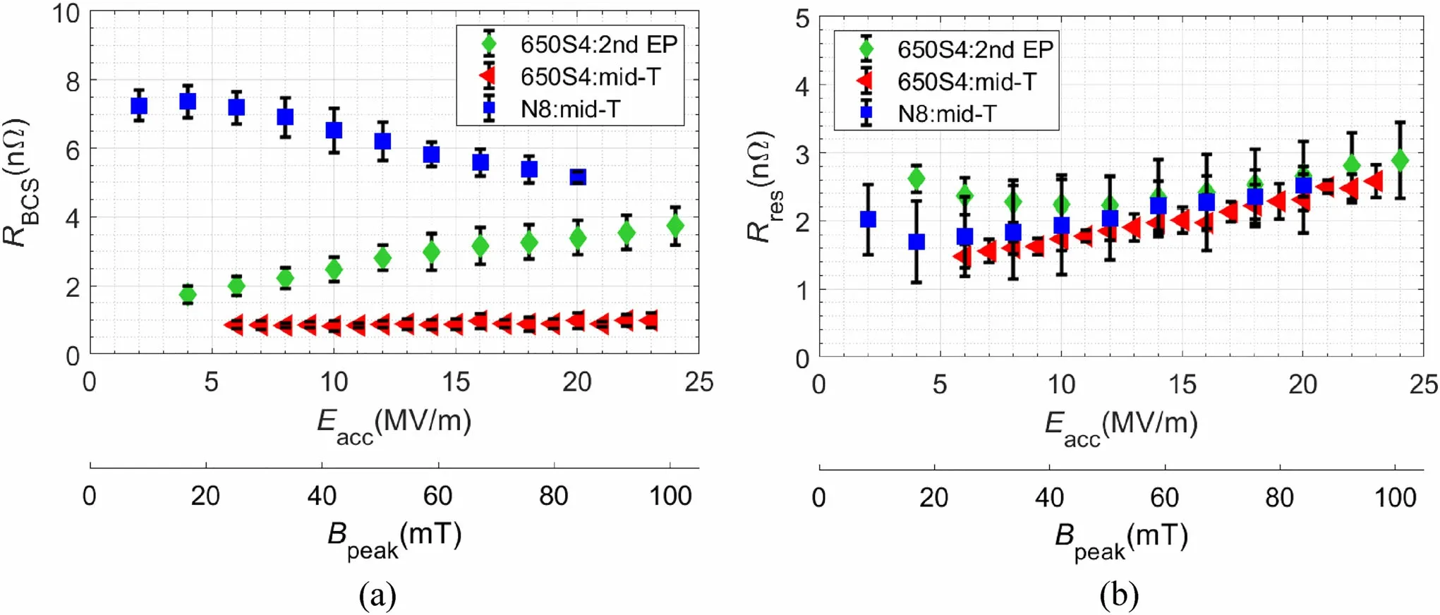
Fig. 6 (Color online) BCS resistance and residual resistance for 650S4 and N8. a RBCS; b Rres
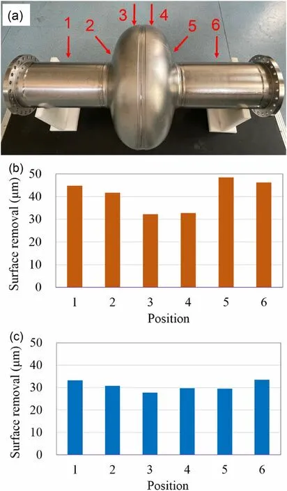
Fig. 7 (Color online) EP removal of 650S4: a red arrows and numbers indicate the locations where thickness was measured;b surface removal of the 1st EP; c surface removal of the 2nd EP
The vertical test results for samples 650S4 and 650S5 are shown in Fig. 9. The Q0values of both cavities decreased slightly as a function of Eacc,which is typical for cavities processed with EP.The high-field Q-slope(HFQS)phenomenon was not evident for either of the cavities.Finally, 650S4 and 650S5 achieved a higher gradient after the 2nd EP than after the 1st EP, and they quenched at ~41.0 MV/m(Bpeak≈172 mT)with Q0of 1.5 × 10¹⁰and ~41.6 MV/m (Bpeak≈ 175 mT) with Q0of 2.3 × 10¹⁰, respectively. The Bpeakvalues of 650S4 and 650S5 were exceptionally high and exceeded the lower critical field(BC1= 170 mT)of niobium.No field emission was observed during the vertical test of 650S4, which is rare for such large cavities. During the vertical test of 650S5, the field emission began to increase above a gradient of 37 MV/m and was weakly accompanied by X-ray radiation. In summary, a significantly high RF field was achieved by 650S4 and 650S5 during the vertical tests,which indicated that the inner surfaces of both cavities were smooth and defect-free. Thus, the 2nd EP, HPR,assembly, low-temperature baking, and vertical tests for 650S4 and 650S5 were successful.This indicated that cold EP could enhance the quench RF field of 650 MHz cavities.Moreover,the values of Q0for 650S4 after the 1st and 2nd EP were almost the same.
The RBCSand Rresvalues of 650S4 during the 2nd EP were also estimated, as shown in Fig. 6. RBCSincreased from ~2 nΩ at 4 MV/m to ~4 nΩ at 24 MV/m,which is higher than that achieved by mid-T furnace baking.Hence,30 μm removal by the 2nd EP was sufficient to eliminate the effects of mid-T furnace baking. Moreover, Rreswas between 2 and 3 nΩ, similar to the value after mid-T furnace baking.
6 Conclusion
State-of-the-art surface treatments for improving the performance of CEPC 650 MHz single-cell cavities were investigated in this study.The combination of BCP and EP was successfully applied to 650S4 and 650S5, both of which exceeded the accelerating gradient of 40 MV/m,which is remarkably high. Finally, 650S4 quenched at ~41.0 MV/m (Bpeak≈172 mT) with Q0= 1.5 × 10¹⁰,whereas 650S5 quenched at ~41.6 MV/m (Bpeak≈175 mT) with Q0= 2.3 × 10¹⁰. Previously, large elliptical cavities seldom exceeded the Eaccof 40 MV/m or Bpeakof 170 mT, which is the lower critical magnetic field of niobium. BCP is easy but has low precision, whereas EP is complicated but has high precision. Therefore, the‘‘BCP + EP’’ recipe is attractive and efficient for surface treatments of mass SRF cavities, such as CEPC, CiADS,and PIP-II.
Mid-T furnace baking of 650S4 and 650S5 demonstrated ultrahigh quality factors at medium RF fields. Q0exceeded 8 × 10¹⁰at 22 MV/m for both 650 MHz singlecell cavities. An extremely low RBCS(~1.0 nΩ) was achieved at 2.0 K; this is a notable result. Moreover, the anti-Q-slope behavior was not observed,which is similar to that of nitrogen-doped 650 MHz cavities.
The research presented in this paper is beneficial for improving the performance and enhancing the fundamental understanding of P-band (0.23–1 GHz) elliptical cavities,which are of interest for next-generation high-energy colliders, proton sources, and synchrotron light sources. The surface treatments of the SRF cavity developed in this study are simplified and easy to replicate, which will benefit researchers working in the field of SRF.

Fig. 8 (Color online) Inner surface of 650S4 (cell). a Before the 2nd EP; b after the 2nd EP

Fig. 9 (Color online)Comparison of vertical test results of 650 MHz single-cell cavities
Author contributionsAll authors contributed to the study conception and design. Material preparation, data collection, and analysis were performed by Peng Sha, Wei-Min Pan, and Song Jin. The first draft of the manuscript was written by Peng Sha, and all authors commented on previous versions of the manuscript. All authors read and approved the final manuscript.
杂志排行
Nuclear Science and Techniques的其它文章
- Thermal hydraulic characteristics of helical coil once-through steam generator under ocean conditions
- Lifetime estimation of IGBT module using square-wave loss discretization and power cycling test
- Optimization of the cavity beam-position monitor system for the Shanghai soft X-ray free-electron laser user facility
- A beam range monitor based on scintillator and multi-pixel photon counter arrays for heavy ions therapy
- Research on manufacture technology of spherical fuel elements by dry-bag isostatic pressing
- Beam–beam effects and mitigation in a future proton–proton collider