Design and development of an ACCT for the Shanghai advanced proton therapy facility
2022-11-21HongZhangJunZhouLiRuiHouSunAnShiQuanXuYouChunLiuPengJiaoZhangJieSongYueLinZhang
Hong Zhang· Jun-Zhou Li · Rui Hou · Sun An · Shi-Quan Xu ·You-Chun Liu · Peng-Jiao Zhang · Jie Song · Yue-Lin Zhang
Abstract The Shanghai advanced proton therapy facility is a proton cancer treatment device designed and built by the Shanghai Institute of applied physics at the Chinese academy of sciences. The accelerator part comprises a proton linear accelerator (linac) injector and a circular synchrotron. An alternating current current transformer(ACCT) is used for non-intercepting beam current measurement at the drift tube linac exit.According to the beam characteristics,the ACCT is required to complete real-time beam current and pulse width measurements at currents of 3–30 mA, frequencies of 1–10 Hz, and pulse widths of 40–400 μs. In this paper, we report the design and development of an ACCT. The designed ACCT was simulated using CST Microwave Studio, and calibrated using an oscilloscope and signal generator. Variations in the output signal of the ACCT were investigated as a function of ceramic gap size, number of coil turns, and resistance.According to the simulation and experimental results, the optimal number of coil turns was found to be 30. In addition, a low-pass filter was adopted to filter the noise introduced during long-distance signal transmission using a coaxial cable with the length of 20 m. The calibration results show that the corresponding rise time of the ACCT is 800 ns with the sensitivity of 8.2 V/A and a droop of less than 1%, meeting the design requirements.
Keywords Beam current monitors·ACCT·Particle beam diagnostics
1 Introduction
Proton beams have played an essential role in cancer therapy in the past few decades [1–4]. The Shanghai Advanced Proton Therapy facility (SAPT) is the first domestic proton radiotherapy facility developed independently by the Shanghai Institute of applied physics and Shanghai advanced research institute and is in the clinical trial stage at present [5]. The accelerator of the SAPT constitutes a linear proton injector and a circular synchrotron. The linac injector includes an electron cyclotron resonance ion source, a four-wing radio frequency quadrupole, and an alternating phase focused-type drift tube linac (DTL). The linac produces a proton beam with the energy of 7.0 MeV, which is injected into the circular synchrotron [5–9]. For a pulsed beam extracted from the DTL, the beam current measurement is generally completed using intercepting or non-intercepting monitors[10–13]. In an intercepting monitor, the particle beam is injected into a target, such as a Faraday cup, to produce a measurable signal;however,this is unsuitable for real-time beam current measurements of many accelerators [12,13].In contrast, the non-intercepting monitor obtains the electromagnetic signal from electromagnetic induction, while the charged particle beam passes through the monitor without affecting the normal operation of the accelerator facilities [12–18]. According to the beam properties from the DTL of the SAPT,the beam current monitor is required to complete measurements of the beam current and pulse width at various currents of 3–30 mA, frequencies of 1–10 Hz, and pulse widths of 40–400 μs in real-time.Therefore, the alternating current current transformer(ACCT), a kind of non-intercepting beam current monitor,has been adopted to complete real-time measurements of the proton beam extracted at the DTL exit port.
ACCT is an evolution of the active transformer first proposed by Hereward in 1960,with the advantages of low noise, low DC offset of the output signal, and excellent long-term stability [12, 13, 18, 20]. When a charged particle beam passes through the toroid, it acts as the primary winding of the ACCT. The secondary winding of the ACCT is wound directly and evenly around a circular iron core. The ACCT sensor is connected to an operational amplifier to obtain a long droop time constant when measuring a charged particle beam with a pulse width longer than several microseconds[13].The sensor and electronics are connected using a cable for long-distance signal transmission. In addition, the offset of the ACCT output signal is very close to zero, because the output voltage of the operational amplifier is zero when no primary current passes through the sensor.
In this paper, the design and development of an ACCT for the DTL of the SAPT are introduced. An O-ring seal was used to complete the vacuum seal of the sensor,with a feedthrough used to complete the connection between the toroid of the sensor and the coaxial cable.A polyimide film with the thickness of 10 μm was used as the internal insulation material for the sensor.Then, the airtightness of the sensor was tested to ensure that its vacuum leak rate could meet the design requirements of less than 1.0 × 10⁻¹¹Pa m3/s. The designed ACCT was simulated and optimized using CST Microwave Studio to ensure that its droop time constant was less than 1%for measuring the signal with the pulse width of 400 μs. In addition, variations in the output signal of the ACCT sensor were examined regarding ceramic gap size,number of coil turns,and resistance. Considering that the length of the coaxial cable was 20 m, we also experimented with the background noise introduced during the signal transmission from the sensor to the electronics.Based on the test results,a low-pass filter was adopted to improve measurement accuracy. Finally, the developed ACCT was tested and calibrated using a digital signal generator and an oscilloscope.
2 Design of ACCT
In general, an ACCT consists of a sensor, a signal transmission line, and signal processing electronics, as shown in Fig. 1a. The main body of the sensor is a toroid with a shielding shell. According to Ref. [20], this device can be considered a feedback integrator, and the corresponding equivalent circuit is presented in Fig. 1b. Considering the currents in the circuit, we obtained the following equation:
In addition, Uican be calculated by:

It can be seen that the use of an operational amplifier could reduce the resistance because Rf/A is much smaller

Fig. 1 Structure and corresponding equivalent circuits of alternating current current transformer (ACCT)
than RL.The feedback resistor,with resistance Rf,was used for range switching. The corresponding remaining resistance is determined by the cable resistance RL, which is usually a few ohms or less[12,13,18].However,for actual devices, additional resistance will also be introduced into the signal transmission line owing to the adaptors, joint of wires, and excess enameled wire left in the sensor when assembling the toroid. These resistances should also be considered besides RL. Such an amplifier is also called a transimpedance amplifier or current-to-voltage (I–V) converter[13].Further,the rise time τriseof the ACCT mainly depends on the selected operational amplifier and the corresponding electronics. In addition, the inductance of the toroid L is given by [12, 13, 18]:

where N is the number of coil turns, μ0is the permeability of vacuum, and μris the relative permeability of the iron core with inner radius ri, outer radius ro, and thickness l.According to Eqs.(7)and(8),the droop time constant is proportional to the square of N and μrfor the same toroid size. In general, N is the only parameter that can be adjusted to optimize sensor performance because of the limitations of the sensor size and iron core material properties.However,the current of the secondary windings ibis inversely proportional to the number of coil turns N. Therefore, the sensor sensitivity decreases with an increase in N, resulting in a decrease in the signal amplitude, which can thus become too close to the background noise.Therefore,it is essential to choose a suitable number of coil turns to optimize the performance of the ACCT.
2.1 Mechanical design of the sensor
The designed sensor comprised two shielding shells, a toroid, and a ceramic gap, as shown in Fig. 2. It was designed with reference to the Bergoz in-flange CT technique [19]. The shielding shells were made of 316 L stainless steel (relative permeability <1.03) to avoid magnetization by the magnetic field generated by the proton beam and surrounding facilities, which may affect the measurement accuracy of the ACCT.The two shielding shells secured with four screws also served as flanges connecting adjacent accelerator facilities. In addition, the grooves mounted on the shielding shells were used to fix the ceramic gap, and air extraction grooves were used to reduce the vacuuming time of the sensor, as depicted in Fig. 2d.A ceramic gap was added to interrupt the electrical conductivity of the beam tube near the sensor, thus preventing the flow of the image current inside the toroid[12,13,18].In addition,the ceramic gap could separate the toroid and proton beam, preventing the sensor from being damaged by the proton beam irradiating the toroid when it entered the sensor abnormally. The adopted ceramic gap was made of 95% Al2O3ceramic with the advantages of high-temperature resistance,high mechanical strength,and good insulation performance. The iron core was made of cobalt-based amorphous (CoNiFeSiB) because of its high relative permeability (approximately 105). Moreover, this material is a thin film that can be easily customized to the required toroid size with the advantage of being insensitive to mechanical stress. A steel concave shell made of 316 L stainless steel with the thickness of 1 mm was applied on the iron core to reduce its outgassing rate. The iron core had a thickness of 24 mm, inner diameter of 52 mm, and outer diameter of 67 mm. Regarding the requirement of a low outgassing rate, we selected a polyimide-enameled copper wire with the diameter of 1 mm to establish the toroid. Polyimide has been widely used as a versatile insulating material in vacuum environments because of its high heat resistance, excellent thermal and electrical insulation, and low outgassing rate [21–26]. In addition, the polyimide film with thickness of 10 μm was used to complete the internal insulation of the sensor, as shown in Fig. 2e.
During the measurement, the toroid was in vacuum,whereas the coaxial cable and electronics were in the atmosphere. Therefore, a high-performance feedthrough(ANDESUN technology, ADS-FT-SMA-009, impedance of 50 Ω, max current <5 A) was adopted to connect the toroid and coaxial cable (EZCON Technology, RG142/P/500,length of 20 m).The feedthrough was welded onto the top of the shielding shell,as displayed in Fig. 2.One end of the toroid was tin soldered to the inner conductor of the feedthrough, while the other was fixed to the inner surfaceof the shielding shell as the earthing. Furthermore, the insertion loss of the selected coaxial cable was less than 0.2368 dB for a signal with a frequency of less than 1 MHz,as can be seen in Fig. 3.Therefore,we believe that there is no attenuation for long-distance transmission of low-frequency weak signals using the selected coaxial cable. A standard SMA interface with the impedance of 50 Ω was employed for the feedthrough and coaxial cables.

Fig. 2 (Color online)Schematics of a designed sensor and b cross section of the designed sensor;photographs of c developed sensor in the facility, d shielding shell of the sensor with mounting grooves,and e inner insulation of the sensor using the polyimide film

Fig. 3 Insertion loss test results for the selected coaxial cable with length of 20 m
2.2 I–V converter

Fig. 4 Circuit diagram of the I–V converter
The core of the ACCT electronics is an I–V converter,and the corresponding circuit diagram is provided in Fig. 4.The use of a low-speed amplifier can reduce the high-frequency noise of the operational amplifier at the expense of increased rise times [12, 13]. In this study, we selected a high-speed operational amplifier (OPA657, 1.6 GHz gainbandwidth product) with low distortion to obtain a short rise time and high amplification factor for the ACCT.Potentiometer RW was used to change the amplification factor of the operational amplifier. The input and output ends of this module both constituted a standard SMA interface with the impedance of 50 Ω.The input current of this module was designed to be within the range of 10–30 mA,and the minimum amplification factor was 100.In addition, a low-pass filter is required to improve the measurement accuracy, because the operational amplifier amplifies the background noise introduced during longdistance signal transmission. The low-pass filter was designed according to the frequency amplitude characteristic curve of the sensor signals.
3 Experimental setup
In this study, the designed sensor was simulated using CST Microwave Studio. The performance of the ACCT was investigated as a function of ceramic gap size,number of coil turns, and resistance. The airtightness of the developed sensor was tested using a helium mass spectrometer leak detector (INFICON UL1000FAB) to ensure that it met the design requirements. In addition, the developed ACCT was tested using a digital signal generator (UTG932) and oscilloscope (LDS2052CL), and the corresponding test platform is depicted in Fig. 5. The output amplitude of the ACCT was measured using an oscilloscope measurement tool. The minimum measurement step of the oscilloscope was 4 μs when the pulse width was 400 μs. Therefore, the output amplitude of the ACCT was measured at time axes of 396 μs (Va) and 4 μs(Vb).Additionally,a resistor(providing constant resistance of 100 Ω)was connected in series in the circuit as a load to match the internal resistance of the signal generator(100 Ω). The length of the coaxial cable used in the experiments was 20 m. Additionally, the amplification factor of the I–V converter was maintained as a constant.The signal generator was used to provide square wave signals with rise and fall times of 15 ns each, duty ratio of 0.04%, and frequencies of 1–10 Hz. Moreover, the signal to be measured is separated using a parallel extension cable. One end of the parallel extension cable was connected to the oscilloscope for display purpose (CH2 channel), while the other end passed through the center of the sensor. During the experiment, we studied the output signal of the I–V converter and designed a low-pass filter accordingly. The output signals of the I–V converter were also sampled using an ADC(AD9226,resolution of 12 bits,sample rate of 20 MSPS) for analysis using MATLAB R2016a.The droop time constant was studied as a function of the number of coil turns in the experiment. Finally, we calibrated the developed ACCT under the design parameters using a signal generator and an oscilloscope.

Fig. 5 (Color online) Test platform for the developed ACCT
4 Results and discussion
4.1 Simulation results of ACCT
The time-domain solver of CST Microwave Studio was used to complete the simulation of the designed ACCT,which is helpful for understanding the output performance of the ACCT and completing the mechanical design.During the simulation, we simplified the structure of the ACCT to reduce the simulation time; the corresponding model is displayed in Fig. 6. The distance between the enameled wire and the iron core was 0.2 mm. The output signal of the simulation is the voltage between the two ends of the coil,which was measured using a voltage monitor,as shown in Fig. 6b. The electrical conductivity of the iron core is 120 S/m, and the corresponding complex relative permeability is presented in Fig. 7. The signal to be measured was a square-wave signal supplied by a current source with the current of 30 mA and rise and fall times of 15 ns each, as shown in Fig. 6a. Additionally, the pulse width of the signal used in the simulation was 400 μs, and the corresponding duty ratio was increased to 2/3 (the actual duty cycle was 0.04%)to reduce the simulation time.According to Eq. (7), RLwas considered during the simulation, while other stray capacitances could be neglected.Therefore, based on the test results, the resistance was set to 5 Ω. However, neglecting the I–V converter with its amplification factor will lead to much lower rise time and signal amplitude of the simulation results compared with those of the actual results. Furthermore, this simplification neglects external environment interference (e.g., background noise) in long-distance signal transmission and the noise introduced by the operational amplifier.
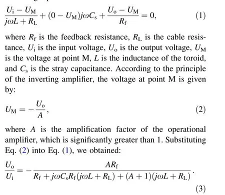
First, we studied the performance of the ACCT as a function of the ceramic gap thickness and width, as shown in Fig. 8a and b.During the experiment,the number of coil turns was 30 and remained constant.It can be seen that the ceramic gap size has almost no influence on the ACCT performance. Therefore,only the mechanical requirementsmust be considered when designing the sensor. Owing to the limitations of the sensor size (flange type of CF63 and sensor thickness of less than 40 mm), we selected a ceramic gap with the inner diameter of 38 mm, outer diameter of 47 mm,and width of 9 mm.Furthermore,we studied the influence of the number of coil turns on the droop and the sensitivity of the ACCT, as can be seen in Fig. 8c. The corresponding droop was calculated using the maximum amplitude Vmaxand the minimum amplitude Vmin(time =400 μs)of the output signal,as shown in Table 1.It can be observed that the amplitude of the sensor signal is inversely proportional to the number of coil turns.This is because the current in the secondary winding of the current transformer is inversely proportional to the number of coil turns. (The primary winding is one)-The resistance remained constant in the simulation; therefore, the output amplitude of the sensor was inversely proportional to the number of coil turns. When the number of coil turns is high, the designed ACCT requires an operational amplifier with a very large gain-bandwidth product to amplify the sensor signal.According to the simulation results, the number of coil turns must be approximately 30 to obtain a droop of less than 1% for measuring a signal with the pulse width of 400 μs. To further reduce the droop of the ACCT, the resistance of the signal transmission line should be reduced,but this is more difficult to achieve than changing the number of coil turns. Moreover, we adjusted the resistance to 1 MΩ with 30 coil turns,as shown in Fig. 8d.At this time, the device corresponds to a passive current transformer, which directly uses a constant resistance to complete the conversion from current to voltage, rather than the I–V converter. It can be observed that the corresponding droop time constant is lower. Therefore, an I–V converter is essential for the designed ACCT when measuring signals with long pulse widths.

Fig. 6 (Color online)a Sectional view of the simplified model and b voltage monitor used in this simulation

Fig. 7 (Color online) Complex relative permeability results of the iron core
4.2 Test results of sensor airtightness
The developed sensor is required to achieve sufficient airtightness and a low outgassing rate. Figure 9 displays the test results for sensor airtightness.It is apparent that the vacuum leak rate of the sensor can reach 5.3 × 10⁻¹²Pa m3/s after 15 min, meeting the design requirements of less than 1.0 × 10⁻¹¹Pa m3/s. Therefore,use of polyimide film to provide sensor insulation in a vacuum environment is feasible. However, the current design scheme also has shortcomings, i.e., the pumping speed of the developed sensor is slow because of its complex internal structure. Although the developed sensor could meet the design requirements in a short time, it first took a long time (approximately 4 h) to obtain a vacuum leak rate of less than 1.0 × 10⁻¹³Pa m3/s (the limit of the leak detector).
4.3 Test results of ACCT
During the measurement, the I–V converter amplified both the background noise and sensor signalssimultaneously, resulting in a decrease in measurement accuracy, as shown in Fig. 10a and b. In this test, N = 30 and the current of the signal to be measured was 30 mA.We studied the background noise when the signal to be measured was zero; the corresponding spectra are presented in Fig. 10c and d. It can be observed that the background noise is mainly distributed in the high-frequency region with a frequency of more than 10 kHz.Therefore, we adopted a 4th-order active low-pass filter(operational amplifier:TL082)with the cutoff frequency of 500 kHz to complete filtering.It is clear from Fig. 8e and f that the background noise was filtered out. However, the low-pass filter caused a slight overshoot at the rising edge with a width of less than 2 μs. Additionally, we examined the influence of the low-pass filter on the performance of the ACCT, the results of which are displayed in Fig. 11.The rise time of the ACCT was approximately 800 ns for the low-pass filter with the cutoff frequency of 500 kHz.In contrast, the corresponding rise time was approximately 1.6 μs when the cutoff frequency was 250 kHz.Compared with the simulation results,there is a significant increase in the rise time of the ACCT, which is mainly due to the I–V converter with a low-pass filter. Therefore, we chose the low-pass filter with the cutoff frequency of 500 kHz, and the associated circuit diagram is presented in Fig. 12. The corresponding output voltage of the module was limited in the range of - 3–3 V.
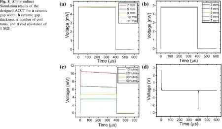
Fig. 8 (Color online)Simulation results of the designed ACCT for a ceramic gap width, b ceramic gap thickness, c number of coil turns, and d coil resistance of 1 MΩ

Table 1 Droop results of ACCT with varying number of coil turns from simulation

Fig. 9 Vacuum leak rate of the sensor versus time

Fig. 10 (Color online) a and b Output signals of the I–V converter;spectra of background noise in c linear coordinates and d logarithmic coordinates; e and f Output signals of the active low-pass filter. The yellow line represents the signal to be measured, and the blue line represents the output signal of the ACCT

Fig. 11 (Color online) Rise time results of ACCT using the I–V converter with low-pass filters having cutoff frequencies of a 500 kHz and b 250 kHz. The yellow line is the signal to be measured, and the blue line is the output signal of ACCT
The performance of the ACCT was studied as a function of the coil turns, as shown in Fig. 13. The corresponding droops are listed in Table 2.The signal used in the test was a square wave with the current of 30 mA and pulse width of 400 μs. When the number of coil turns was 10, the output amplitude of the ACCT was approximately 740 mV; when the number of coil turns was 40, the signal amplitude was only 190 mV. The corresponding droop of the ACCT with 10 coil turns was approximately 20%,while the droop was only 0.54% for ACCT with 40 coilturns.Thus,the higher the number of coil turns,the higher the sensitivity of the ACCT, and the worse the droop time constant. Under the premise of meeting the design requirements, choosing fewer coil turns is beneficial for obtaining higher sensitivity. Therefore, we chose 30 coil turns. At this time, the output amplitude Vawas 246 mV.To measure a signal with the pulse width of 400 μs, the output amplitude Vbof the ACCT was 244 mV with the corresponding droop of 0.81%, which meets the design requirements.
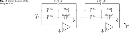
Fig. 12 Circuit diagram of the low-pass filter

Fig.13 (Color online)Output signal results of ACCT with different numbers of coil turns of a 10,b 20,c 30,and d 40.The yellow line is the signal to be measured, and the blue line is the output signal of ACCT

Table 2 Droop of the ACCT with different coil turns from the experiment
4.4 Calibration results of the developed ACCT

Fig. 14 (Color online) Output signal results of ACCT for measured currents of a 1 mA, b 3 mA, and c and d 30 mA. The yellow line is the signal to be measured, and the blue line is the output signal of the ACCT
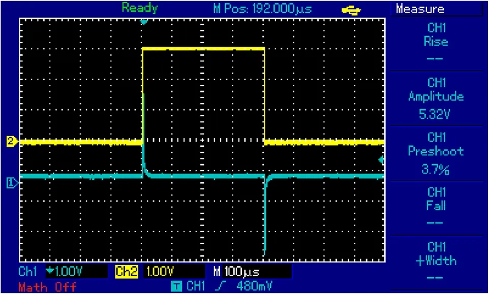
Fig.15 (Color online)Output signal results of ACCT without the I–V converter. The yellow line is the signal to be measured, and the blue line is the output signal of the ACCT
The developed ACCT was calibrated using a signal generator and an oscilloscope, as shown in Fig. 14. When the signal to be measured was 3 mA, the output amplitude Vaof the ACCT was 24.89 mV; when the signal to be measured was 30 mA, the output amplitude Vawas 246 mV, as shown in Fig. 14d. In addition, we tested the output signal of the sensor without the I–V converter, as shown in Fig. 15. The signal to be measured was a square wave with a current of 30 mA and pulse width of 400 μs.The resistance of the oscilloscope(1 MΩ)was constant for I–V conversion. It is apparent that the signal waveform is consistent with the simulation result for the 1 MΩ resistance. The amplitude difference between the simulation and test results can be attributed to the inductance and insertion loss of the coaxial cable when transmitting sharp pulse signals, and the measurement error of the oscilloscope when measuring sharp pulse signals. Therefore, we believe that simplification of the ACCT used in the simulation is feasible.In addition,the measured calibration data were analyzed using linear regression, as depicted in Fig. 16a. According to the fitting results, the sensitivity of this ACCT is 8.2 V/A with good linearity.Furthermore,the amplitude of the output signal at the same timeline(396 μs,Va)remained nearly unchanged as the pulse width differed,as can be seen in Fig. 16b. The oscillation of the ACCT signals can be attributed to the background noise and measurement error of the oscilloscope. Therefore, it is not necessary to recalibrate the developed ACCT when the pulse width changes. In summary, the designed ACCT has high measurement accuracy with low measurement errors and meets the design requirements.
5 Conclusion
In this paper,we reported the design and development of an ACCT for the SAPT. According to the beam characteristics, the designed ACCT is required to perform realtime measurements of proton beams with beam currents of 3–30 mA, frequencies of 1–10 Hz, and pulse widths of 40–400 μs. Considering the requirements of a low outgassing rate, we chose polyimide-enameled copper wire and polyimide film to create the toroid and complete internal insulation of the sensor, respectively. A high-performance feedthrough was adopted to complete the signal transmission between the toroid and coaxial cable with the length of 20 m. The simulation results indicate that only the mechanical requirements of the sensor must be considered when designing an ACCT. In addition, a low-pass filter with the cutoff frequency of 500 kHz was employed to filter out background noise and improve the measurement accuracy. The rise time of the ACCT was calculated as 800 ns, which is dependent on the I–V converter with a low-pass filter. The developed ACCT was then tested and calibrated using a signal generator and an oscilloscope.Based on the simulation and test results, the optimal number of coil turns was determined to be 30. From the calibration results, the sensitivity of 8.2 V/A was obtained with good measurement linearity. In future, the designed ACCT will be optimized to obtain a longer droop time constant and to solve the overshoot caused by the low-pass filter.
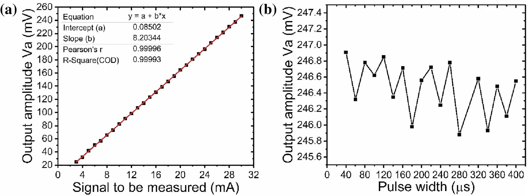
Fig.16 a Calibration results of the developed ACCT when the pulse width of the signal to be measured was 400 μs.b Signal amplitude results of ACCT vs. pulse width with current of 30 mA
Author contributionsAll authors contributed to the study conception and design. Material preparation, data collection and analysis were performed by Hong Zhang, Jun-Zhou Li and Sun An. The first draft of the manuscript was written by Hong Zhang and all authors commented on previous versions of the manuscript. All authors read and approved the final manuscript.
杂志排行

Nuclear Science and Techniques的其它文章
- Thermal hydraulic characteristics of helical coil once-through steam generator under ocean conditions
- Lifetime estimation of IGBT module using square-wave loss discretization and power cycling test
- Optimization of the cavity beam-position monitor system for the Shanghai soft X-ray free-electron laser user facility
- A beam range monitor based on scintillator and multi-pixel photon counter arrays for heavy ions therapy
- Research on manufacture technology of spherical fuel elements by dry-bag isostatic pressing
- Beam–beam effects and mitigation in a future proton–proton collider