Data-Driven Human-Robot Interaction Without Velocity Measurement Using Off-Policy Reinforcement Learning
2022-10-26YongliangYangZihaoDingStudentRuiWangHamidrezaModaresSeniorandDonaldWunsch
Yongliang Yang,, Zihao Ding, Student, Rui Wang,,Hamidreza Modares, Senior, and Donald C. Wunsch,
Abstract—In this paper, we present a novel data-driven design method for the human-robot interaction (HRI) system, where a given task is achieved by cooperation between the human and the robot. The presented HRI controller design is a two-level control design approach consisting of a task-oriented performance optimization design and a plant-oriented impedance controller design. The task-oriented design minimizes the human effort and guarantees the perfect task tracking in the outer-loop, while the plant-oriented achieves the desired impedance from the human to the robot manipulator end-effector in the inner-loop. Data-driven reinforcement learning techniques are used for performance optimization in the outer-loop to assign the optimal impedance parameters. In the inner-loop, a velocity-free filter is designed to avoid the requirement of end-effector velocity measurement. On this basis, an adaptive controller is designed to achieve the desired impedance of the robot manipulator in the task space. The simulation and experiment of a robot manipulator are conducted to verify the efficacy of the presented HRI design framework.
I. INTRODUCTION
ROBOTIC manipulators have played an important role in engineering applications, such as master-slave teleoperation systems [1], construction automation [2], space engineering [3], to name a few. When the human is restricted by the physical limitation or when operating in a harsh environment is required, the robot manipulators can handle strenuous and dangerous work that is difficult or impossible for human operators. However, robot manipulators cannot completely replace the human because of robots' lack of highlevel of learning and inference ability. Therefore, the interaction between the human and the robot could take the best of human and robot capabilities. Successful applications of human-robot interaction (HRI) system designs include physiotherapy [4], human amplifier [5], assistive haptic device[6]. In this paper, we employ the two-level design framework[7] for the HRI systems with novel outer-loop and inner-loop designs to obviate the requirement of velocity measurement and the complete knowledge of system dynamics.
Related Work:The interaction of the robot and the human is different from that between the robot and the environment.For the case when the robot only interacts with the environment, the control system is task-oriented and is designed based on feedback from the environment. Classical manipulator controller design mainly focuses on stability consideration [8], [9], or performance optimization with a given objective index [10]. In contrast, the HRI is more useful since the human intention and experience could be taken into account and exploited to guide the controller design to cooperate with the robot [11]. For example, in some cases, the reference cannot be measured directly by the sensors of the robot. The vision and tactile sensation of humans could provide guidance for the robot controller design. In this paper,we exploit the human to perceive the task-oriented reference,which is allowed to be unknown to the robotic manipulator.
Another motivation of the human-robot collaboration is the high-level performance planned by the human. Stability is a basic-level requirement for the controller design. The highlevel performance specifications, such as desired reference and constraints, might not be specified directly to the robot manipulator but can be perceived by the human and transmitted to the robotic manipulator via interaction. In the robot manipulator controller design problem, the impedance model is widely used to achieve the desired spring-damping dynamics from the environment interaction to the reference tracking error [12]–[14]. In this way, robustness, feasibility,and safety of the robot control systems can be furtherguaranteed [15]–[17]. Robot impedance control using the advanced method can be found in [18], [19]. In impedance control design, the impedance model is usually known a priori. However, the desired impedance model is usually not unique. In this paper, the human is involved in the performance specification to determine the optimal impedance parameters with respect to the target of human effort minimization and perfect reference tracking. In contrast to existing results, such as [11], [20], the presented manipulator torque input design in this paper does not require the measurement of the robotic manipulator end-effector velocity while still guaranteeing satisfactory results.
Reinforcement learning (RL), a methodology that investigates performance optimization with consideration about the interaction between the intelligent agent and the environment [21], has been widely used in sequential decision problems, such as optimal control problem [22]–[25], robust stabilization [26], [27], and differential games [28]–[30], as well as real-world applications, including transportation system [31], cruise control [32], to name a few. The off-policy RL method, a model-free version of the RL algorithm, allows one to learn and improve a policy different from the policy applied to the system [33], [34]. This feature allows one to obviate the requirement of the knowledge of the system dynamics and learn about the consequence of a policy without even applying it to the system. In addition, in some applications, the task for the robotic manipulator system might not be repetitive, where the iterative method using data resampling is not suitable for the online feature. The offpolicy RL technique is able to efficiently reuse the data sampled for learning purposes [35]. That is, the learning phase and the data generation process are completely decoupled, and resampling is no longer required. In this paper, we exploit the off-policy RL technique for the task-oriented impedance optimization design to optimize the impedance parameters for a given performance.
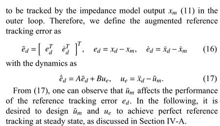
Presented Design:In this paper, we develop a novel twolevel HRI system with task-oriented impedance optimization and plant-oriented adaptive robot controller design. For taskoriented impedance optimization, the human effort is minimized with unknown human dynamics, and the impedance optimization is achieved using the data-driven offpolicy RL technique. In the plant-oriented manipulator controller design, adaptive control is developed to compensate for the unknown robotic dynamics with an additional velocityfree filter to avoid the requirement of the end-effector velocity measurement. The interaction between the human and the robot is taken into account for the robot manipulator design.The overall design scheme is given in Fig. 1, which could assist the human to minimize the effort to achieve a specific task with effort minimization and reduced measurement demand, and without the requirement of HRI model knowledge.

Fig. 1. The hierarchical human-robotic interaction algorithm. 1) Inner loop design: The unknown robot dynamics (8) from the human force xh to the Cartesian end-effector x behaves like the prescribed robot impedance model (11). 2) Outer loop design: The red dotted line represents the interaction between the human and the robot.
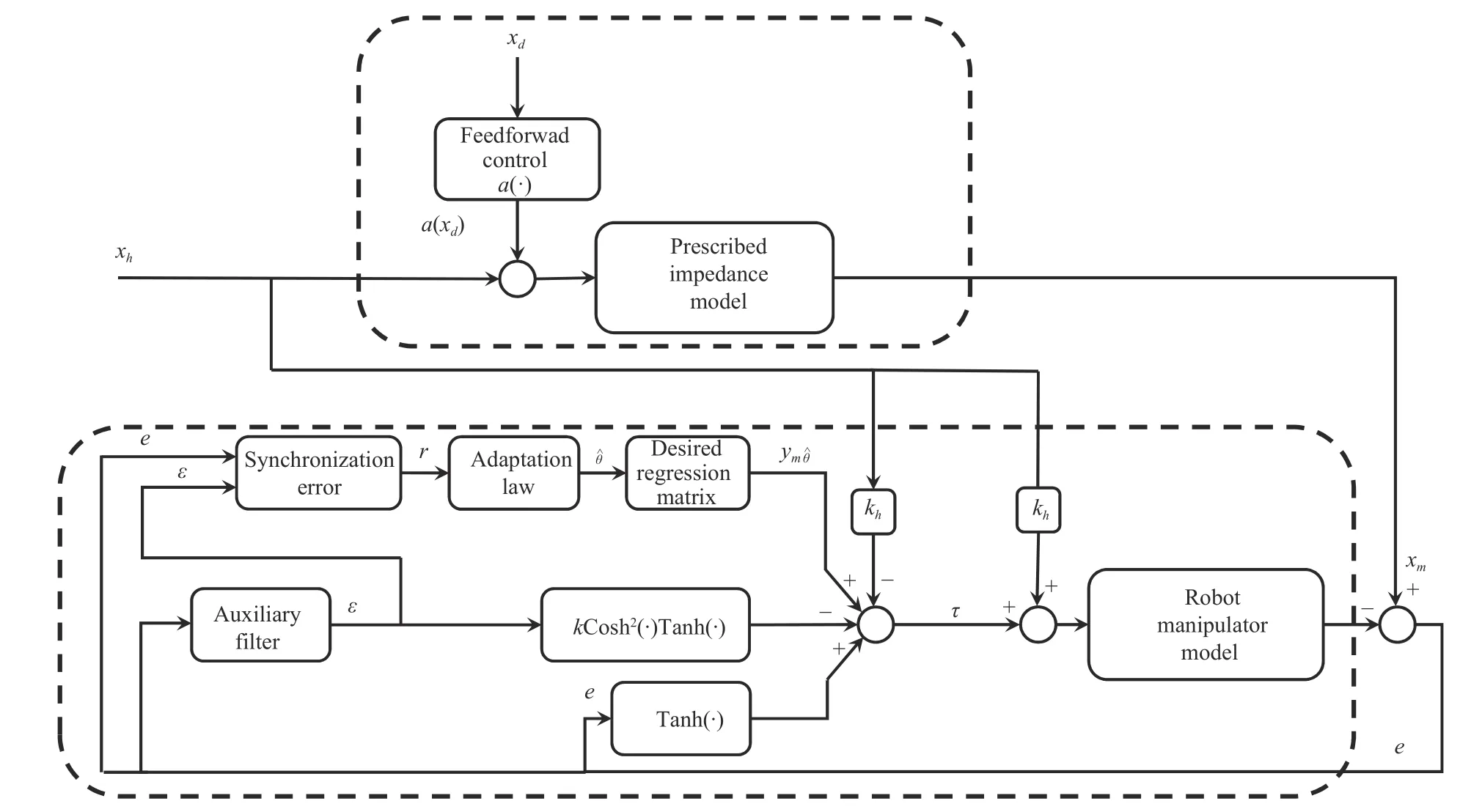
Fig. 2. Impedance following in plant-oriented inner-loop design.
Contributions:The contribution of this paper is two-fold.First, the off-policy RL method is used for the HRI taskoriented controller design, where the behavior policy is used to generate the online data for learning, and the target policy is updated in the learning phase. In contrast to thepartiallymodel-free RL method developed in [7], the human and impedance dynamics can becompletelyobviated while optimizing the impedance parameters to minimize the human effort and achieve perfect reference tracking. Second, in the HRI plant-oriented inner-loop, a nonlinear sliding mode synchronization error is defined for the adaptive impedance controller design. Differently from [11], in the plant-oriented design, the adaptive impedance design does not require the velocity measurement of the manipulator end-effector. In addition, the presented adaptive velocity-free robot controller guarantees the asymptotic impedance-following performance.
The remainder of this paper is as follows. In Section II, we briefly review the dynamic model of the HRI system in the task space. In Section III, we define a novel nonlinear sliding mode synchronization error and present the velocity-free controller design for the robotic manipulator. In Section IV,the data-driven off-policy RL algorithm is used to avoid the requirement of complete system dynamics for the impedance optimization aiming at minimizing the human effort and achieve perfect reference tracking. The presented novel innerand outer-loop designs are verified in Section V using a twolink planar robot manipulator. Experimental results using the developed HRI framework are investigated in Section VI. In Section VII, concluding remarks are drawn in the end.
II. PROBLEM FORMULATION
A. Preliminaries
The following notations and inequalities from [36] are required for subsequent analysis.
Considerx=[x1···xn]T∈Rnandy=[y1···yn]T∈Rn.First, the functions t anh(·) and c osh(·) are the scalar hyperbolic functions. Define the following two vector/matrix functions
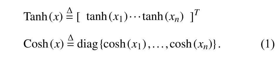
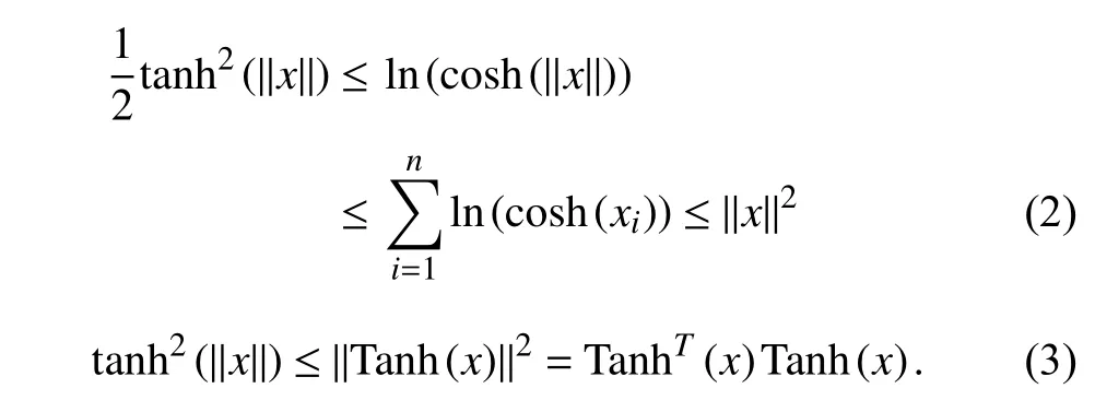
The following facts about T anh(x) and C osh(x) hold.
B. System Description
1) Robot Manipulator Models in Joint and Task Spaces
Consider the dynamical model ofn-link robot manipulator in joint space

whereq∈Rnis the position of the robot arm in the joint space,nis the degree-of-freedom,Mq(q)∈Rn×nis the symmetric positive definite inertia matrix,denotes the Corioliscentrifugal matrix,is the Coulomb friction term,Gq(q) is the vector of gravitational forces, τqis the generalized input torque acting at the joints,Khis the gain andxhis the human control effort, andJis the Jacobian matrix.
It is desired to have a description of the end-effectorxin the task space other than the joint variableqin the joint space.Consequently, define the mapping

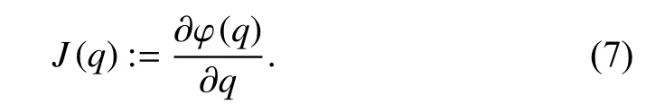
wherex∈Rndenotes the position of the end-effector in thesdimensional task space and φ(·):Rn→Rnis a nonlinear transformation. Using the chain rule, one has

whereJ(q)∈Rn×nis the Jacobian matrix defined as
Suppose that the task space and joint space have the same dimension. Then, the Jacobian matrix is a square matrix.Further assume that the Jacobian matrix is non-singular. Thus,the dynamics of the end-effector in the task space can be written as [17]
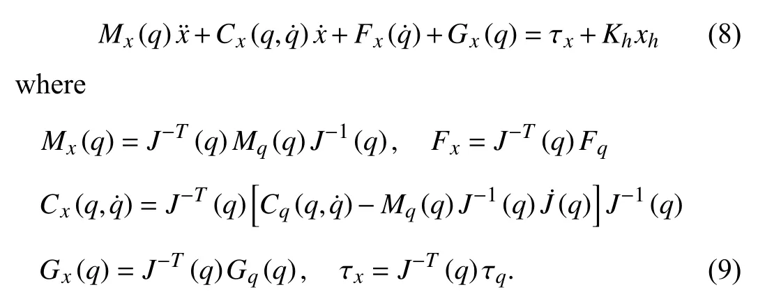
According to [36], [37], the robot manipulator dynamics in the joint space and the task space have the following properties.
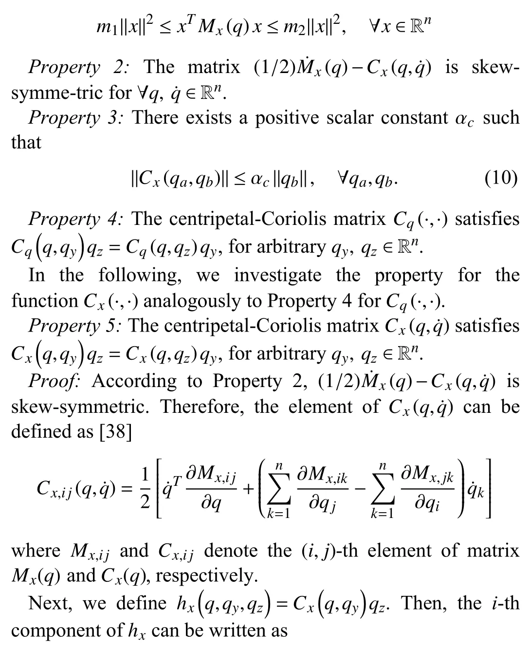
Property 1:For the inertia matrixMx(q), there exist positive constantsm1andm2such that
Additionally, the following common assumption in existing robot manipulator controller designs is utilized in this paper.
Assumption 1:There exist constants βm, βg, βcsuch that

hold, ∀qa,qb,qc∈Rn, wherexa=φ(qa) andxb=φ(qb) with the mapping φ (·) defined in (5).
Remark 1:The task space robot manipulator model (8)considered in this paper has been widely investigated in existing literature [7], [17], [37]. However, this task space model requires the task space and the joint space to have the same dimension, and the Jacobian matrix is also assumed to be non-singular. Special cases with a singular Jacobian matrix should be taken into account [39]. Future work aims to deal with the ill-conditioned Jacobian matrix.
2) Robot Impedance Model
Consider the robot impedance model in the Cartesian space

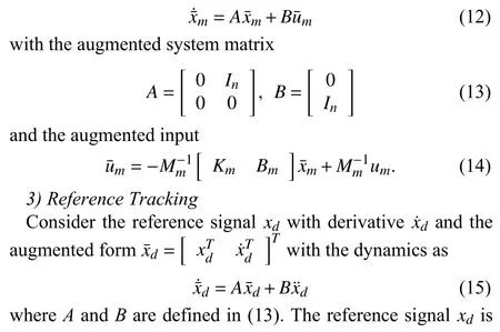
whereumandxmare the input and output of the prescribed robot impedance model respectively,Mm,Bm, andKmare the desired inertia, damping, and stiffness parameter matrices,respectively. Augmenting the impedance model with the stateyields the dynamics as
4) Human Model
Human control characteristics are complex because various kinds of compensators, such as an oculomotor control, a proprioceptive control, and a neuromuscular control, are related to each other [40]. The neuromuscular dynamics is modeled as the first-order lag [41] and proportion differential(PD) controller [42]. In this paper, we employ the human transfer function as [7]
with the equivalent state space representation
whereKdandKpare the human dynamics parameter,xhis the human effort, anduhis the input to the human to be designed later.
C. Human-Robot Interaction Problem
Problem 1 (HRI with Prescribed Performance):Consider the HRI systems (8)–(19) and the reference signalxd. It is desired to design the input torque of the robot manipulator to assist the human operator in performing a given task with minimum effort and optimize the overall HRI performance.
1) Find the torque input τ in (8) without measurement of the velocitysuch that the model-following errore(t)→0 ast→∞, where the model-following erroreis defined ase=xm−x.
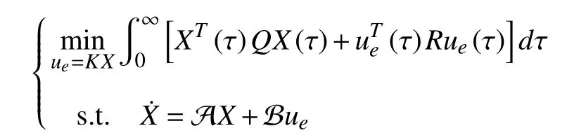
2) Find the optimal impedance model parameters{Mm,Bm,Km} for (11), design impedance control inputumin(11) such that the performance index

is minimized.
Remark 2:Note that the control objective of achievingx→xdis separated into two subtasksx→xmandxm→xdas in Problem 1. The human plays a vital role in the hierarchical framework and can improve the robot tracking performance and significantly reduce the system requirement, which is important in many scenarios. For example, high-accuracy sensing devices are costly, and sensors cannot completely avoid measurement errors. Therefore, it is difficult for the robot to perceive and achieve the original task directly. The involvement of the human can greatly help the robot to perceive the environment.
In the following, Problem 1 is solved by using a hierarchical human-robotic interaction design scheme, which consists of
a) an inner loop design in Section III to guarantee that the unknown robot dynamics (8) from the human forcexhto the Cartesian end-effectorxbehaves like the prescribed robot impedance model (11);
b) an outer loop design in Section IV to help the human minimizing the effort to complete the task with interaction with the robot.
The overall hierarchical human-robotic interaction design is illustrated in Fig. 1.
III. INNER LOOP DESIGN USING PRESCRIBED PERFORMANCE ADAPTIVE CONTROL
In this section, the inner loop design on the robot level is presented to guarantee that the model following from the human effortxhto the robot manipulator end-effectorxbehaves like the impedance model fromxhtoxm, as shown in Fig. 2. In the inner-loop, the interaction between the human and the robot is exploited for the robotic manipulator input torque design.
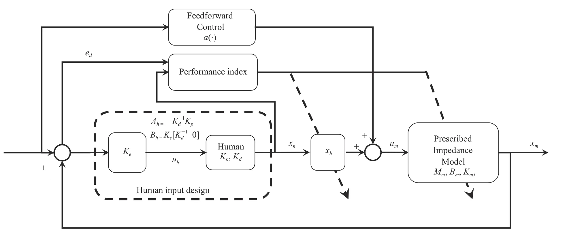
Fig. 3. Task-oriented outer-loop design.
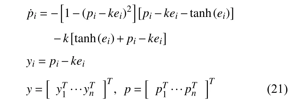
A. Velocity-Free Filter Design
In order to obviate the requirement of the velocity measurement, inspired by [36], we design the velocity-free filter
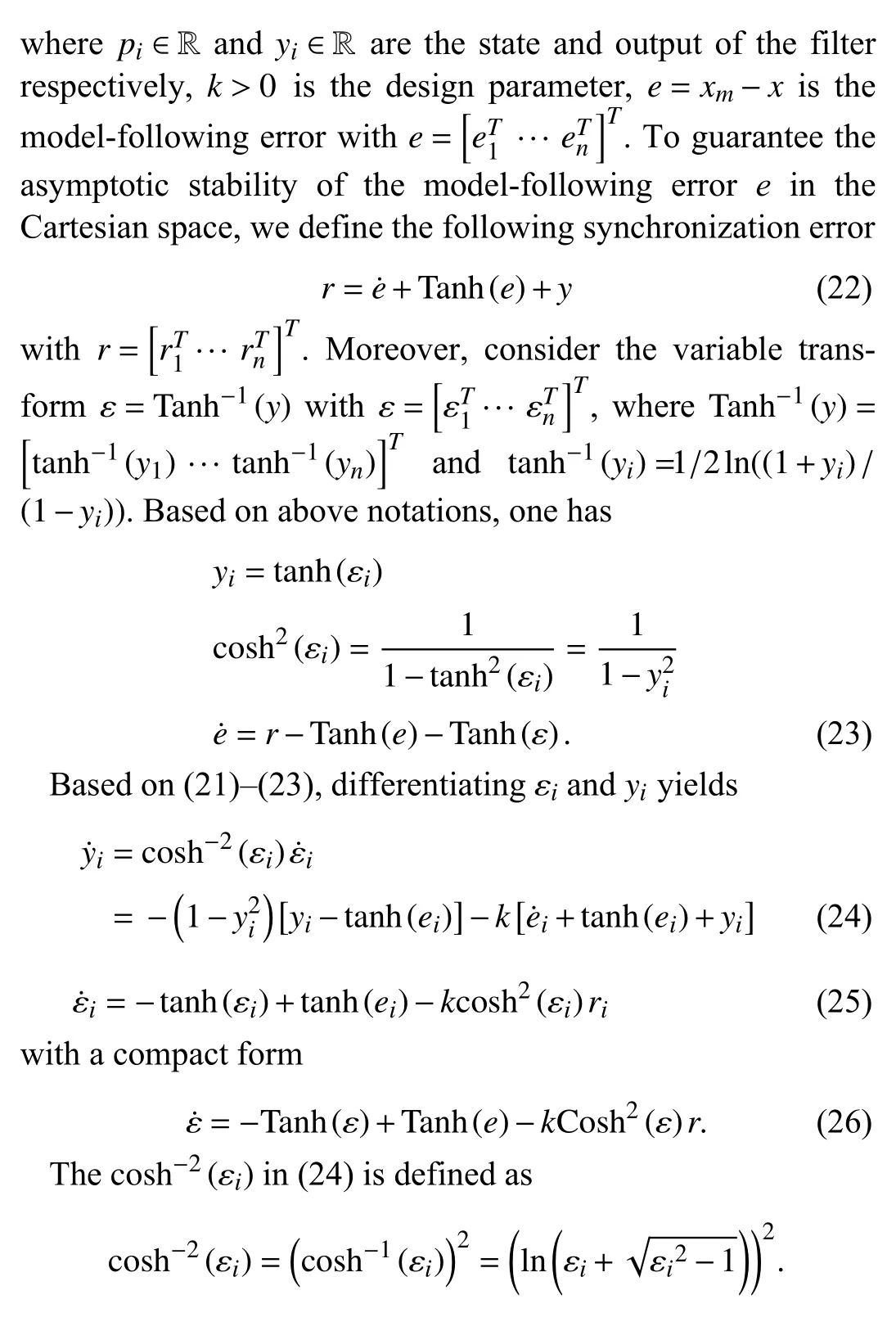
B. Synchronization Error Dynamics
From (22), one has
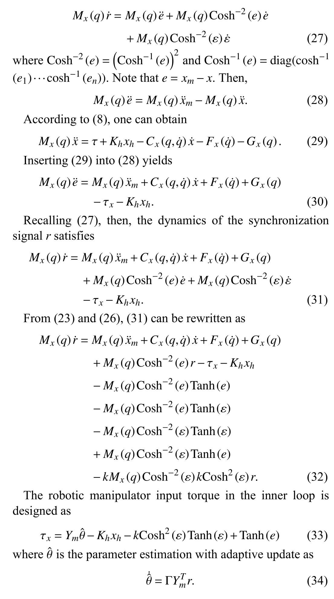
C. Robot Dynamics With Matched Condition
In the following, we investigate the case when the robot dynamics satisfies the matched condition.
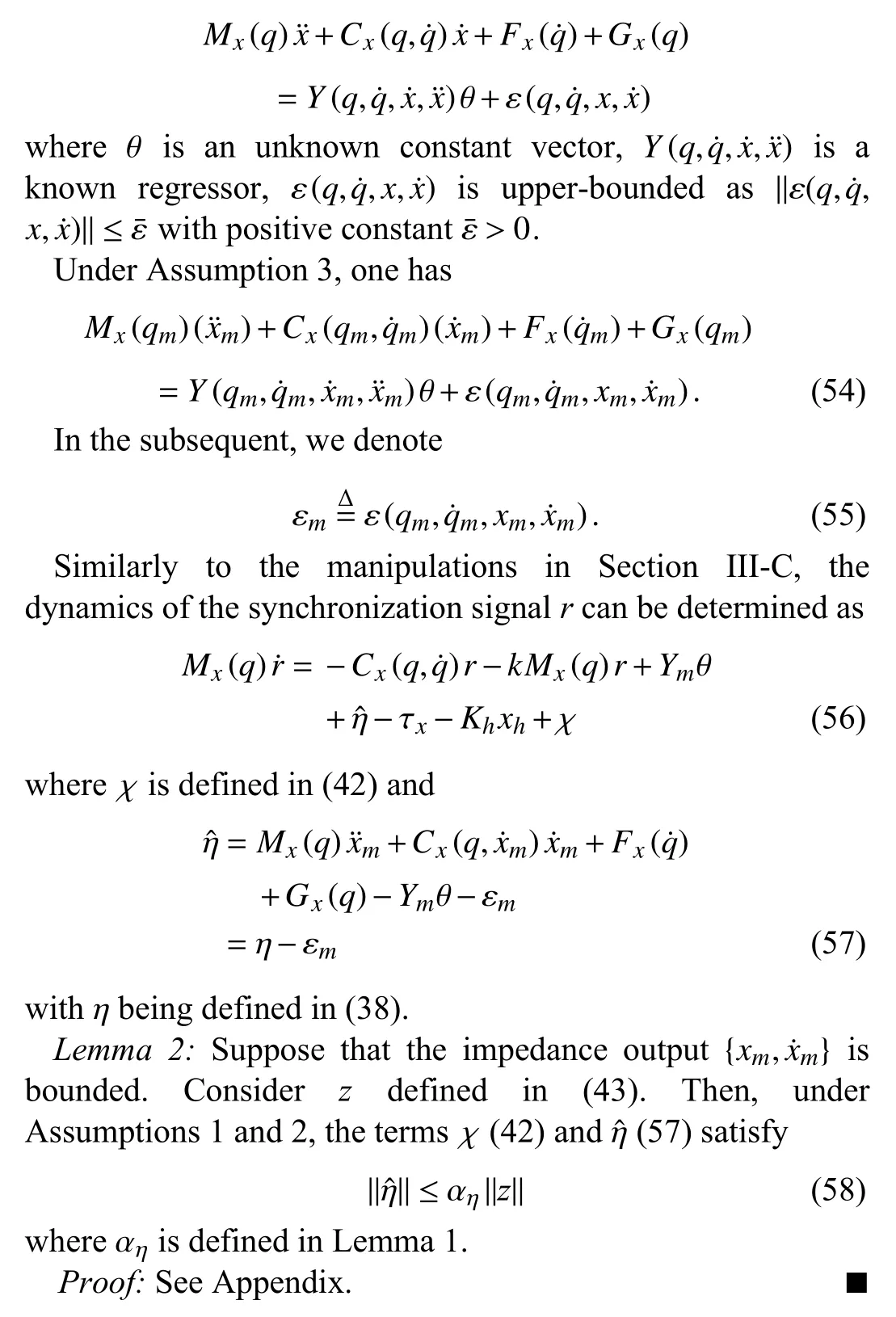
Assumption 2:The robotic dynamics (8) can be parameterized as
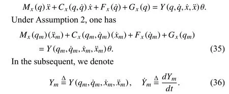
Assumption 2 indicates that the robot dynamics can be linearly parameterized, which is a commonly used [1], [14],[37], [43]. By adding and subtracting the termsCx(q,q˙)randYmθ to (32), one has

From (22) and the fact thate=xm−x, adding and subtracting[Tanh(e)+Tanh(ε)] to π, and applying Property 5 to π yield

Adding and subtracting the following term

Inserting (40) into (38), the dynamics of the synchronization signalrcan be determined as
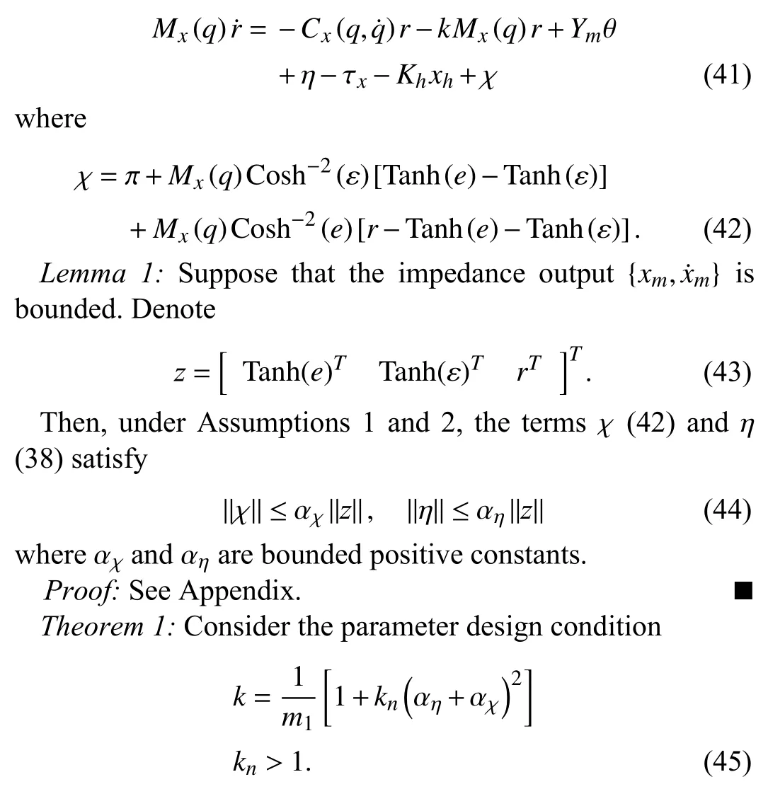
Then, the input torque design (33) and the adaptive parameter update (64) guarantee that the model-following erroreconverges to the origin asymptotically.
Proof:Inserting the input torque (33) into (41), one can obtain
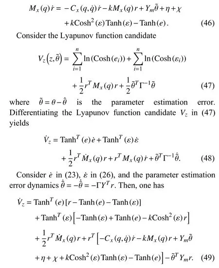
Applying Property 2 and opening the terms in the bracket in(49), one has
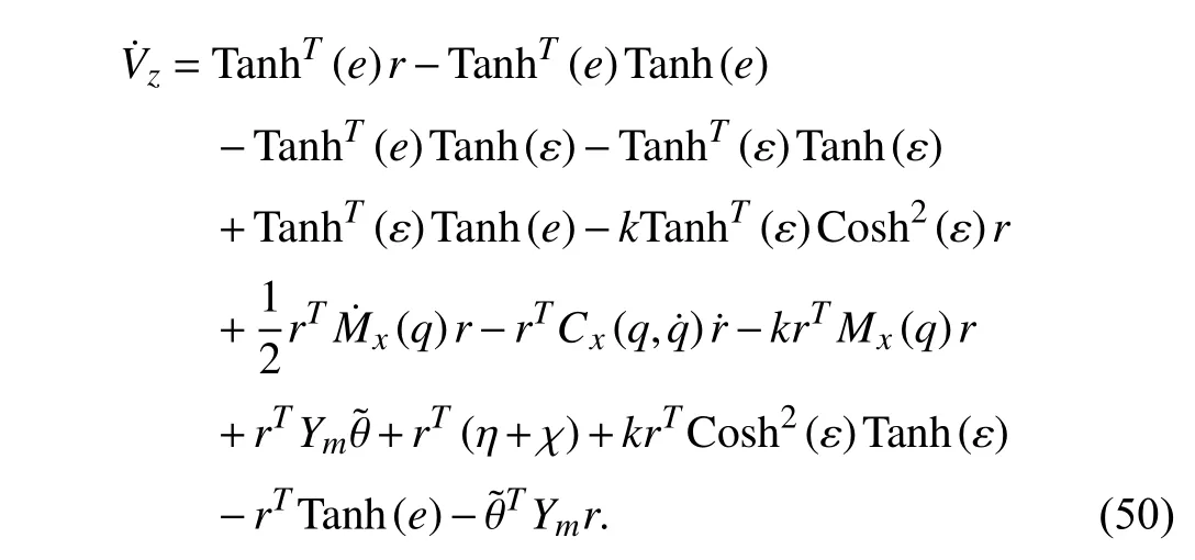
After some manipulations and applying Property 1, the Lyapunov function candidate derivative can be determined as
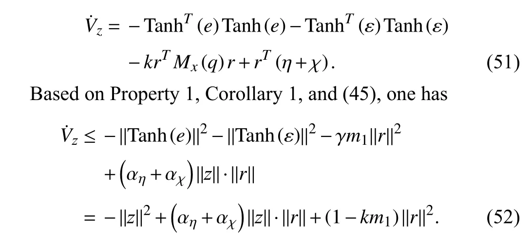
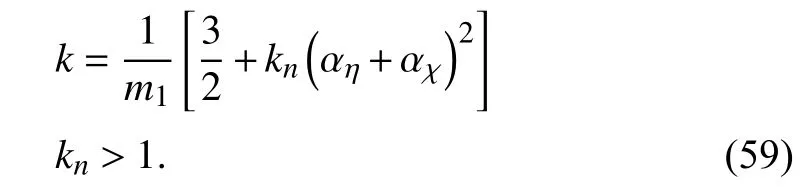
With the parameter design (45), one has −kn(αη+αχ)2=1−km1. Then, By completing the squares on the right hand side of (52), one can obtain
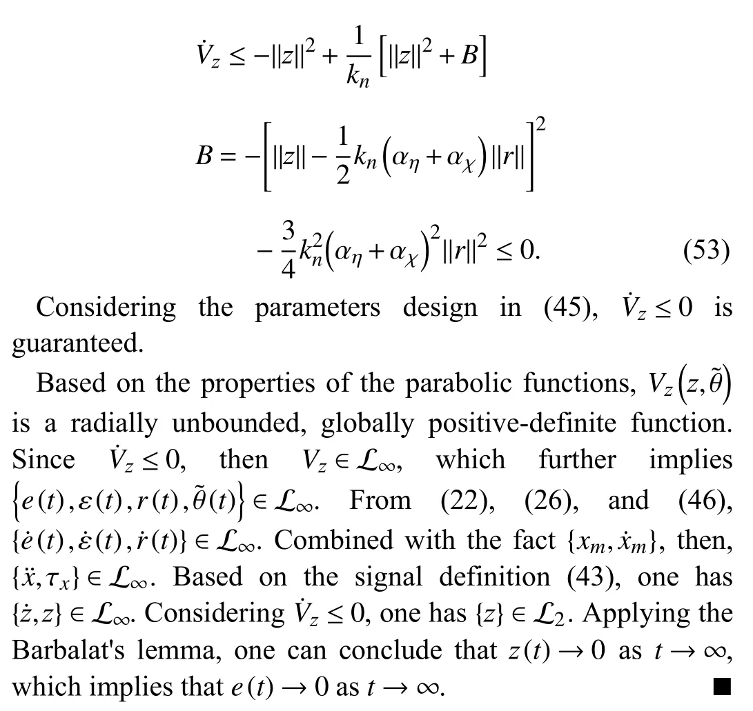
D. Robot Dynamics with Unmatched Condition
In the following, we investigate the case when the robot dynamics does not satisfy the matched condition.
Assumption 3:The robotic dynamics (8) can be parameterized as
Theorem 2:Consider the parameter design condition
Then, the input torque design (33) and the adaptive parameter update (64) guarantee that the model-following error e converges to small neighborhoods of the origin.
Proof:Inserting the input torque (33) into (56) yields

Consider the Lyapunov function candidate defined in (47).DifferentiatingVzyields
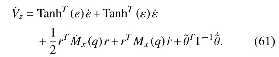
Considering the fact (57) and using similar manipulations as in Theorem 1, one can obtain

Following the steps (52) and (53), one has
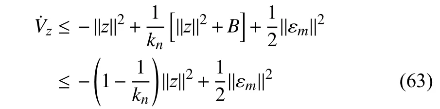
whereBis defined in (53). Following discussions in Theorem 1,the boundedness ofecan be guaranteed.
Remark 3:For implementation purpose, the parameter estimation can be determined by the calculation as

whereYmandare defined in (36). As shown in (34), the adaptive parameter learning depends on the synchronization signalr, which is determined by the velocity tracking errore˙(22). However, from (64), by using the velocity-free filter(21), only the filter outputyand model-following erroreare required to update the parameter estimation. On this basis, the input torque design (33) does not require the velocity measurement of. Therefore, the filter design (21) is completely velocity-free.
Remark 4:It is worthwhile to discuss the inner-loop design in terms of the following aspects.
1) The results in this section are mainly concerned with the scenario when the Cartesian task space and joint space have the same dimension. For under-actuated and redundant robots,the joint space dimension mismatches the Cartesian space dimension and the Jacobian matrix is not a squared matrix. In these cases, typical approaches, such as direct kinematic inversion in the position regime and the Jacobian transformation in the velocity regime [44], can be used to determine the Jacobian matrix.
2) For the Cartesian space robot manipulator dynamics (8),both the matched parameterization (Assumption 2) and the unmatched parameterization (Assumption 3) are investigated in Sections III-C and III-D, respectively.
IV. OUTER LOOP DESIGN USING OFF-POLICY REINFORCEMENT LEARNING
In this section, we present the feedback and feedforward designs for the impedance model and the human input such that the closed-loop system is a linear dynamical system with external control input in a feedback form in a feedback form,as shown in Fig. 3.
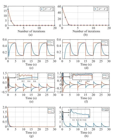
Fig. 4. The simulation results of the outer loop. xd represents the target trajectory, and xm is the output of the impedance model. e d =[ed1 ed2]T and are the position tracking error and the velocity tracking error of the presented design, respectively. xh=[xh1 xh2]T denotes the human force input. (a) The convergence process of the iterative matrix P(k). (b) The convergence process of the iterative matrix K(k) . (c) The trajectory of xm1.(d) The trajectory of xm2 . (e) The tracking error of xm1. (f) The tracking error of xm2. (g) The human force input. (h) The human force total input.
A. Outer Loop Closed-Loop Dynamics
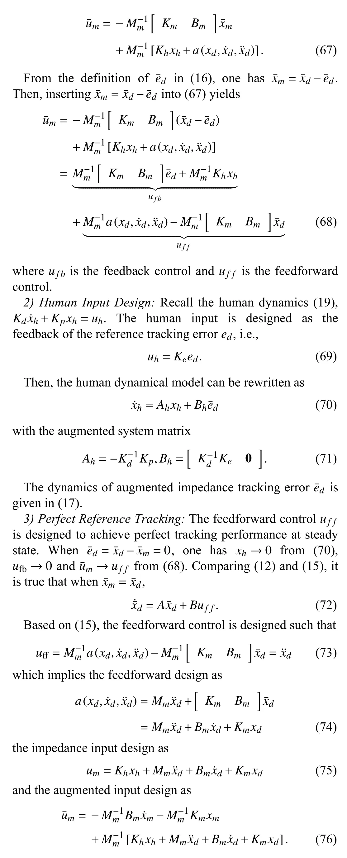
1) Impedance Input Design:Recall the impedance model(11), which can be rewritten as
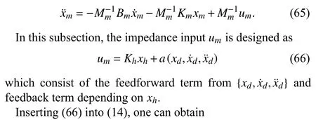
B. Performance Optimization for Outer Loop
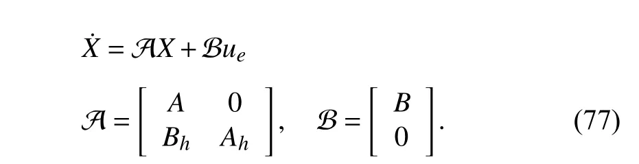
Denote the augmented state as. From (70)and (17), the dynamics ofXcan be expressed as
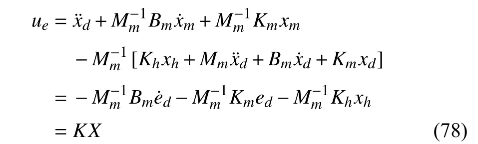
Inserting now (76) into (17), one has the impedance control inputuein the feedback form as
with the feedback gain

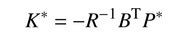
Theorem 3:Consider the closed-loop system (77) with the impedance model (12), human operator dynamics (19). Then,the optimal value ofK∗which minimizes the performance index (20) is given by
wherePis the solution to the algebraic Riccati equation(ARE)

withQ=diag(γ1In,γ2In,γ3In),R=γ4In. Then, the optimal feedback control that solves Problem 1 is determined by

Proof:First, the outer-loop design in Section IV-A yields the closed-loop dynamics as a linear dynamical system (77)with linear feedback (78). Based on the linear quadratic (LQ)optimal theory [45], the ARE solution provides the optimal feedback policy that minimizes the performance index (20).Therefore, the optimal feedback policy for the closed-loop takes the form in (81). ■
Remark 5:Note that in (79), once we obtain the optimal feedback gainK∗, the impedance parametersandBm,Kmare in bilinear form. To simplfy the impedance parameter calculation, without loss of generality, we fix the parameterMmand determine the impedance parametersBm,Kmaccording to (79).
Remark6:The overall design targetx→xdis achieved by the hierarchical outer-loop design (which guaranteesxm→xd)and the inner-loop design (which guaranteesx→xm) as follows.
1) From (16), one hased=xd−xm. Therefore, the human inputuh=Keedonly depends on the desired reference signalxdand the impedancexm. It should be noted that the robot end-effectorxis not required for the human input designuh=Keed. As discussed in Theorem 3, the outer-loop design guarantees the optimality of the performanceV(20) and the convergence of the impedance tracking errored.
2) From (33) and the facte=xm−x, the robot torque input design τxdepends on {ε,xm,x}. As discussed in Theorems 2 and 3, the inner-loop design can guarantee the boundedness of the model-following errore.
C. Model-Free Learning With Complete Unknown Dynamics


?
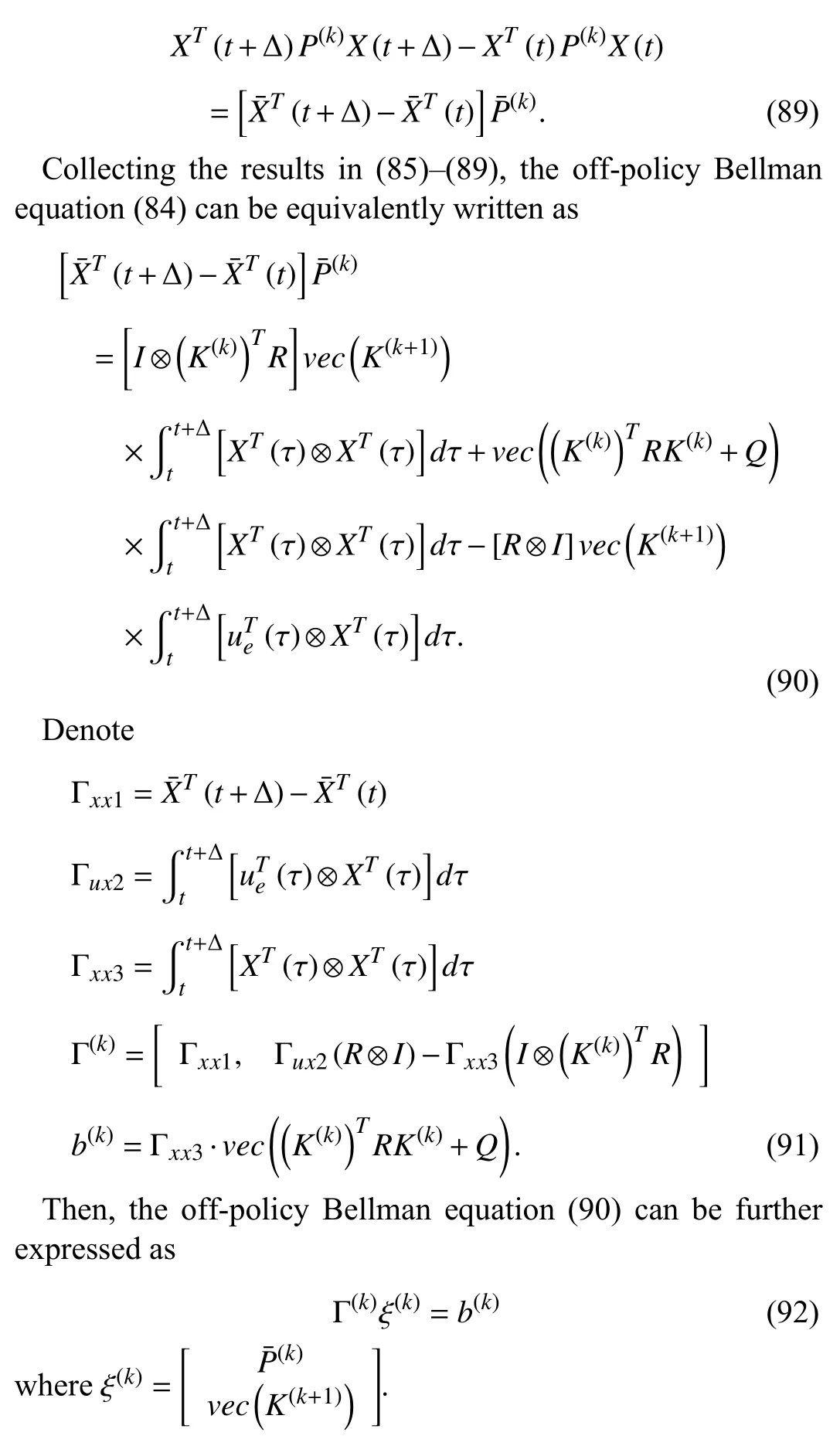
Corollary 1:Algorithms 1 and 2 are equivalent to each other in the sense that the off-policy Bellman equation (84)provides the same iterative value functionP(k)as the solution to the off-policy Bellman equation (82), and the same iterative policy gain updateK(k+1)as the case with on-policy RL in(83).
Proof:The proof is similar to that in [29] and is omitted here. ■
Remark 7:In [7], the integral RL method is developed for the outer-loop design, which is a partially model-free method,i.e., A is not needed but B is still required for the policy improvement. In contrast, in this paper, the off-policy RL based outer-loop design does not require the augmented system dynamics {A,B}. From the definitions of {A,B} in(77), one can conclude that the complete impedance dynamics{A,B} in (13) and the human dynamics {Ah,Bh} in (70) are not required in this paper, which makes the outer-loop design be completely model-free.
Remark 8:To guarantee the existence and uniqueness of the solution to the LS equation (92), probing noise is added into the behavior policyueto guarantee that the data matrix Γ contains sufficiently rich information and is nonsingular. Such requirement is closely related to the persistent excitation in adaptive parameter estimation method [29].
V. SIMULATION STUDY
In this section, the presented design scheme is verified under a real-world scenario of a two-link planar robot manipulator to follow a target reference signal. The reference signal is designed as a periodic squared wave with an amplitude of 0.5. The simulation is carried out by using the Runge-Kutta method with an adaptive step size in MATLAB.
In the outer-loop,xdis the reference trajectory, andxmis the impedance model output. The target in the outer-loop design is to achievexm→xd. Once this target is achieved, the impedance model outputxmprovides the reference for the robotic manipulator to follow. The reference signalxdis now assigned as a squared wave as shown in Figs. 4(c) and 4(d).According to equation (70), the human force is calculated withuhbeing the input andxhbeing the output.
A. Outer Loop Design
In outer-loop design, the system matrix is defined as in (77).The first 0.5 s of the simulation is the time for data collection.The human input is calculated according to (70).
Next, we consider the performance function (20) with γ1=700, γ2=1, γ3=1, γ4=600 . γ1~γ3represent the state regulation performance weights forand ‖xh‖2respectively. γ4denotes the control cost penalty weight for‖ue‖2. The parameters design for γ1~γ4is a trade-off between the control performance and the control cost penalty.Then, the performance optimization in the outer-loop can be formulated as linear quadratic regulation (LQR) problem
whereQ=diag(γ1In,γ2In,γ3In) andR=γ4I2. Based on the LQ optimal control theory [45], the necessary and sufficient condition to the above LQR problem is the ARE equation(80), which can be solved using the complete model knowledge as

In the outer-loop design, we employ the data-driven method to obviate the requirement of complete knowledge for solving the ARE. For the off-policy RL method, the online data are generated using the behavior policy, which is considered as the following for this case,
After enough data are collected, the learning phase is launched by solving the LS equation (92) iteratively, as shown in Algorithm 2. After 15 iterations, the approximate solution to the ARE equation can be shown as

which is close to the model-based solution {P∗,K∗} to the ARE (80).
The evolution of the signals in the outer-loop is shown in Fig. 4. The convergence processes of the iterative matricesP(k)andK(k)are shown in Figs. 4(a) and 4(b). It can be seen that bothP(k)andK(k)converge toward the optimums within 3 iterations. Figs. 4(c) and 4(d) reflect the evolutions ofThe signalsedandare shown in Figs. 4(e) and 4(f), respectively, from which it can be seen that the probing noise is added into the behavior policy during [0,0.5] second for the off-policy RL method to guarantee the existence and uniqueness of the LS equation (92). The human force in the HRI is displayed in Fig. 4(g). Finally, in Fig. 4(h), it can be seen that the outer loop stateXin (77) converges to the origin and the learning policy can stabilize the closed-loop system.
B. Inner Loop Design
In inner-loop design,xmis the impedance model output andxis the robotic manipulator end-effector position. The innerloop design aims to achievex→xm. The impedance model output (xm) is shown in Figs. 4(c) and 4(d).
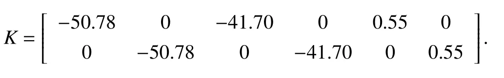
Next, we consider the robot manipulator [37] with jointspace dynamics as in (4)
wheres1=sin(q1),s12=sin(q1+q2),c1=cos(q1) andc12=cos(q1+q2). Following (9), one can obtain the Cartesian space manipulator dynamics (8). For more details about the transformation from joint-space model to Cartesian space model, interested readers are referred to [37]. Finally, we select the torque parameter in (33) ask=[75 75]Tand the adaptive parameter in (34), as Γ =[5 5 5 5 5 5 5]. The value ofkwill affect the convergence of tracking error. Increasing the value ofkwould accelerate the convergence speed.However, a large value ofkwill lead to a large control effort of the manipulator torque input. Therefore, the selection ofkshould guarantee the closed-loop signals boundedness and satisfactory control effort. Additionally, the presented innerloop design is compared with the existing robot manipulator input torque design [20].
1) Case 1 (Matched Condition):In this case, we investigate the type of task space robotic dynamics satisfying the matched condition as discussed in Section III-C. That is, the robotic dynamics can be linearly parameterized under Assumption 2.The simulation results of the inner-loop design are shown in Fig. 5. Figs. 5(a) and 5(b) reflect the tracking results of the manipulator end-effector. Figs. 5(c) and 5(d) show tracking errors of the presented design and method [20], respectively.The average tracking accuracy of the proposed HRI design is 2.4% in contrast to 4.5% using the method in [20], from which one can observe that, with the presented HRI design, the manipulator tracking error has less fluctuations. In addition,compared to [20], in our method, the feedback design does not require the velocity measurement. These results indicate that the presented inner-loop design under Assumption 2 can guarantee the satisfactory tracking performance for the manipulator.

Fig. 5. The simulation results of Case 1. xd represents the target trajectory,and xm is the output of the impedance model. x and xc are the presented method in this paper and the method developed in [20], respectively. em=[em1 em2]T and emc=[emc1 emc2]T are the tracking errors of the presented design and method [20]. τ=[τ1 τ2]T denotes the manipulator torque input.(a) The trajectories of x1 and xm1. (b) The trajectories of x2 and xm2. (c) The tracking error of the manipulator end-effector in a dimension. (d) The tracking error of the manipulator end-effector in another dimension. (e) The manipulator torque input in a dimension. (f) The manipulator torque input in another dimension.
2) Case 2 (Unmatched Condition):This case verifies the situation described in Section III-D. In this case the robotic task space model cannot be linearly parameterized, as shown in Assumption 3. Besides, the manipulator model is considered as

where τdis selected asFrom above equation, one can observe that the manipulator cannot be linearly parameterized due to the existence of τd.
The signals in the inner-loop design are shown in Fig. 6.Figs. 6(a) and 6(b) show the tracking performance of the manipulator actuator. In Figs. 6(c) and 6(d). the tracking errors generated by using the presented design and the method in [20] are displayed, respectively. The average tracking accuracy of the proposed HRI design is 2.1% in contrast to 8.4% using the method in [20]. It can be shown that, with the proposed HRI design, satisfactory tracking performance can be achieved in the presence of τd. In contrast, for the method in [20], the existence of τdresults in large fluctuation. The manipulator input τ=[τ1τ2]Tis shown in Figs. 6(e) and 6(f).From Fig. 6, it is shown that the presented HRI design is more efficient for the unmatched manipulator dynamics compared with the method in [20].
Fig. 6. The simulation results of Case 2. xd represents the target trajectory,and xm represents the output of the impedance model. x and xc are the presented method in this paper and the compared method in [20],respectively. e m=[em1 em2]T and e mc=[emc1 emc2]T are the tracking errors of the presented design and method [20]. τ =[τ1 τ2]T represents the manipulator input. (a) The trajectories of x1 and xm1. (b) The trajectories of x2 and xm2.(c) The tracking error of the manipulator end-effector in a dimension. (d) The tracking error of the manipulator end-effector in another dimension. (e) The manipulator torque input in a dimension. (f) The manipulator torque input in another dimension.
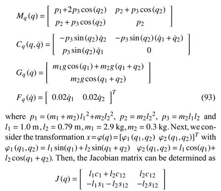
3) Case 3 (Robustness Against Disturbance):In this case,we verify the robustness against disturbance of proposed HRI design, where an additional noise signal is added into the manipulator input. The noise under consideration is a square wave signal with an amplitude of 50 during 1 0 s ~15 s.
The simulation results are shown in Fig. 7. Figs. 7(a) and 7(b) show the tracking results of the presented HRI design and the method in [20], respectively. Figs. 7(c) and 7(d) display the tracking errors, where the average tracking accuracy 2.1%of the proposed HRI design outperforms the tracking accuracy 4.3% of the method in [20]. Therefore, the presented HRI design is more robust compared to the method in [20].Figs. 7(e) and 7(f) show the evolution of manipulator input.These results verify the robustness of the presented HRI design against the disturbance.
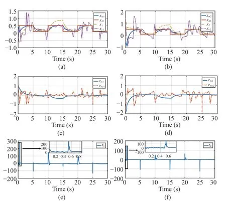
Fig. 7. The simulation results of Case 3. xd is the target trajectory, and xm is the impedance model output. x and xc are the presented method in this paper and the comparison method [20]. em=[em1 em2]T and emc=[emc1 emc2]T are the tracking errors of the presented design and method [20].τ=[τ1 τ2]T are the manipulator input. (a) The trajectories of x1 and xm1.(b) The trajectories of x2 and x m2. (c) The tracking error of the manipulator end-effector in a dimension. (d) The tracking error of the manipulator endeffector in another dimension. (e) The manipulator torque input in a dimension. (f) The manipulator torque input in another dimension.
VI. EXPERIMENT STUDY
In this section, an experiment is conducted to validate the presented HRI design, which is implemented on Universal Robot 5 (UR5) platform as shown in Fig. 8. UR5 has a working space range of 0.85 m and an accuracy of 0.3 mm at the actuator. The PC configurations are Intel(R) Core(TM) i7-7700K 4.20 GHz CPU, 16 G memory, 2 T mechanical hard disk, NVIDIA GeForce GTX 1080TI independent graphics card, and 8 G video memory. The PC is connected to the UR5 robot controller through a local area network. To be consistent with the two-link planar robot manipulator in Section V, in this experiment, we only keep two joints to be controlled and the other joints to be fixed for the operation task.
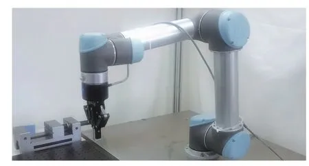
Fig. 8. The Universal Robot 5.
The content of the experiment is that the manipulator under the HRI system control assists the operator in accomplishing the task of moving between two points in the plane. The robot manipulator assists the human operator to finish the operation.The experimental tasks are the same as the simulation, as shown in Fig. 9. Fig. 9(a) shows the task setting, where the end-effector is specified to move between point A and point B.Fig. 9(b) shows the starting location and Fig. 9(c) shows the terminal location. Figs. 9(d) and 9(e) display the tracking performance of the manipulator actuator in the experiment,wherexd=[xd1xd2]Tis the desired position,xm=[xm1,xm2]Tdenotes the output of the impedance model andx=[x1,x2]Tdenotes the measured position of the robot manipulator. Figs.9(d) and 9(e) show the position of the robot’s end-effector in two directions, respectively. The average tracking accuracy of the manipulator during the whole operation is 2.2%.
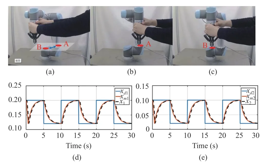
Fig. 9. The process and the result of the experiment. (a) Task setting. (b)Starting position of the task. (c) Terminal position of the task. (d) The position of the robot’s end-effector on one direction. (e) The position of the robot’s end-effector on the other direction.
VII. CONCLUSIONS
This paper investigates the controller design for the HRI system with consideration of both performance optimization and reference tracking. The HRI system consists of two-level design counterparts, the task-oriented outer-loop design, and the plant-oriented inner-loop design. The human effect is taken into account for the impedance model parameter optimization to minimize the human effort in the outer loop.The robot manipulator controller is developed to guarantee that the robot manipulator behaves like the optimized impedance model in the inner loop. The requirement of model knowledge in the outer-loop design is obviated by using the data-driven off-policy RL method. To avoid the requirement of end-effector velocity measurement, we designed a velocityfree filter and an adaptive controller to achieve the desired impedance of the robot manipulator in the task space.Numerical simulation and experiment based on a robot manipulator verify the efficacy of the presented HRI design.
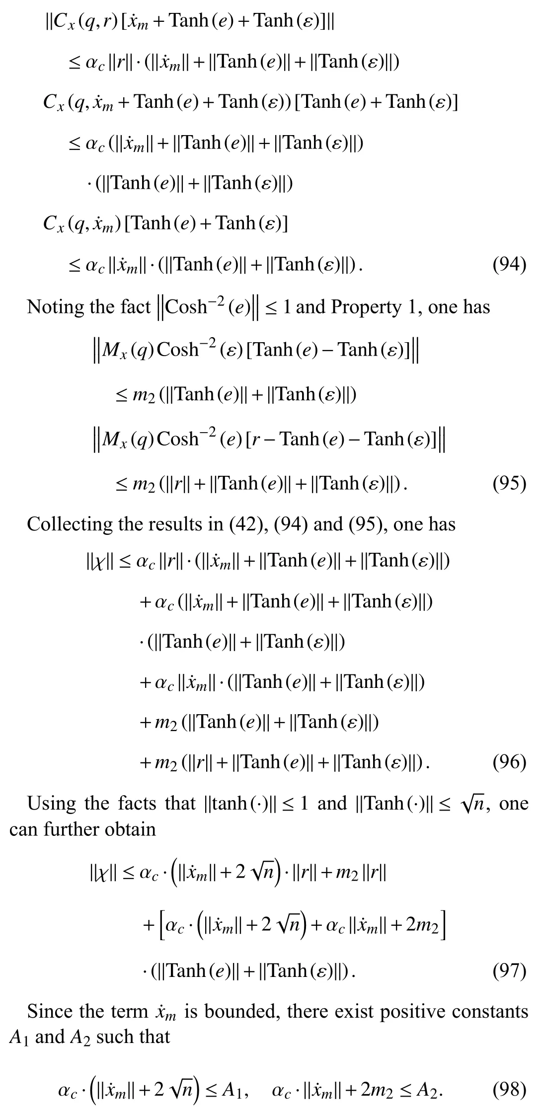
APPENDIX PROOF OF LEMMAS 1 AND 2
Proof of Lemma 1:1) Considering the term χ defined in(42), with Properties 1, 3 and the properties of hyperbolic functions, one has
杂志排行

IEEE/CAA Journal of Automatica Sinica的其它文章
- A Survey of Underwater Multi-Robot Systems
- Robotic Knee Tracking Control to Mimic the Intact Human Knee Profile Based on Actor-Critic Reinforcement Learning
- Dynamic Event-Triggered Scheduling and Platooning Control Co-Design for Automated Vehicles Over Vehicular Ad-Hoc Networks
- Generative Adversarial Network Based Heuristics for Sampling-Based Path Planning
- Integrating Variable Reduction Strategy With Evolutionary Algorithms for Solving Nonlinear Equations Systems
- PID Control of Planar Nonlinear Uncertain Systems in the Presence of Actuator Saturation