Characteristic of Near-surface Microstructure and Its Effects on the Torsion Performance of Cold Drawn Pearlitic Steel Wires for Bridge Cables
2022-10-08ZHANGFanMAOXinpingBAOSiqianZHAOGangZHAOSixinDENGZhaojunHEMengHUANGFangyuQUXi
ZHANG Fan, MAO Xinping, BAO Siqian,3*, ZHAO Gang,3, ZHAO Sixin,DENG Zhaojun, HE Meng,3, HUANG Fangyu,3, QU Xi,3
(1. The State Key Laboratory of Refractories and Metallurgy, Wuhan University of Science and Technology, Wuhan 430081, China; 2. Baosteel Central Research Institute, Wuhan 430080, China; 3. Key Laboratory for Ferrous Metallurgy and Resources Utilization of Ministry of Education, Wuhan University of Science and Technology, Wuhan 430081, China)
Abstract: The characteristic of near-surface microstructure and its effects on the torsion performance of cold-drawn pearlitic steel wires for bridge cables were investigated by focused ion beam-scanning electron microscope, transmission electron microscopy and differential scanning calorimetry. The samples with similar tensile strength before and after hot-dip galvanizing process are, respectively, characterized as delaminated and non-delaminated in torsion test which indicates that the tensile strength is independent of the toughness value(i e, reduction area and torsion ability). It is interesting to find that there exists submicron granular ferrite on near-surface of the wires, which can be attributed to dislocation rearrangement and sub-grains rotation during cold drawing and hot-dip galvanizing process. And their distribution can suggest homogeneousness of deformation degree to a certain extent: the closer to the surface of their distribution, the more homogeneous deformation of the wires. There is a close relationship between the thermal stability of the cementite layer and distribution of granular ferrite: differential scanning calorimetry (DSC) analysis shows that the sample is accompanied by submicron granular ferrite which is located closer to the surface has higher thermal stability under galvanizing temperature (450 ℃). A new mechanism of the torsion delamination of pearlitic steel wires is discussed in terms of the thermal stability of the cementite layer and distribution of granular ferrite.
Key words: cold-drawn pearlite steel wires; torsion performance; near-surface microstructure;submicron granular ferrite
1 Introduction
Pearlite microstructure in steel consists of alternating layers of body-centered cubic (bcc) ferrite and orthorhombic cementite, owing to their excellent combination of strength and ductility. Pearlitic steel wires that made from hypereutectoid steel wire rods are widely used as cable wires for bridges[1-5]. The main manufacturing of the cable wires involves successive cold drawing process, and hot-dip galvanizing treatment which is mainly purposed to prevent corrosion.
Mechanical properties and microstructure evolution of cold drawn pearlitic steel wires have been a topic of considerable scientific research for many years[6-22]. By transmission electron microscopy (TEM),atom probe field ion microscopy (APFIM), three-dimensional atom probe (3DAP), Mössbauer spectroscopy and X-ray photoelectron spectroscopy (XPS), it has been revealed that the microstructure evolution associated to the modifications of macroscopic mechanical properties[6-10,23]. Previous studies have reported that[11-18], during the cold drawing process, a fiber structure and a <110> fiber texture aligned with the wire axis are gradually developed accompanied by the reduction of pearlite lamellar spacing, increase of dislocation density, cementite deformation and decomposition. And the dissolution of cementite into ferrite matrix brings about the local increase of carbon concentration in lamellar ferrite[19]which is considerd to be the main reason for the loss of steel ductility[20].
Tensile strength and torsional properties are the two most important criteria of pearlitic steel wires for bridge cables. The higher the strength of the cable wires, the longer span of the bridge for the same amount of steel used[24]. Therefore, the tensile strength of cable wires for bridges has been developed to 2 000 MPa which is the highest strength grade in engineering applications until now. The torsion properties are assessed by torsion tests, and the torsion delamination that has attracted attention for many years is the primary failure mode in the torsion tests[25-31]. The diffusion of carbon atoms originated from cementite decomposition and the residual stress release have been considered as the main reasons for the torsion delamination[11,30].Some studies reported that torsion delamination could take place in pearlite steel wires without apparent cementite decomposition[4,14]and the residual stress was insensitive to hot-dip galvanizing treatment[32]. After hot-dip galvanizing treatment, even the same group samples with no obvious difference could exhibit completely different torsion properties and tensile strength.Therefore, the influence factor of torsion delamination for pearlite steel wires remains unclear.
The main purpose of this study is to characterize the near-surface microstructure and analyze its effects on the torsion performance of pearlite steel wires.Microstructural observations of cold drawn wires are usually obtained by TEM and scanning electron microscope (SEM) through chemical etching method. In this work, focused ion beam-scanning electron microscope(FIB-SEM) which could use the ion-beam etching near-surface was applied to microstructure observation. This technique is very helpful to obtain truthful near-surface microstructural features.
2 Experimental
The chemical composition of the commercial steel used in the present study is given in the Table 1.The wire rod with a diameter of 14.0 mm had been produced from industrial billet in Baoshan Iron & Steel Co. Ltd: hot rolling to 1173 K finish rolling temperature and quenched by Stelmor conveyor line. The rod was subjected to eight stages of the industrial cold drawing process with a true strain ofε=1.42, and the as-drawn (AD) wires with 6.9 mm diameter were then galvanized under industrial condition (GI): annealing in zinc bath at 450 ℃ for 60 seconds to a diameter of 7.0 mm.
There were two groups of samples (numbered 1 and 2), and each group sample contains two types of wires: the AD wires and the corresponding GI wires.To sample 1, 1-1 signifies the AD wire and 1-2 signifies the corresponding GI wire.
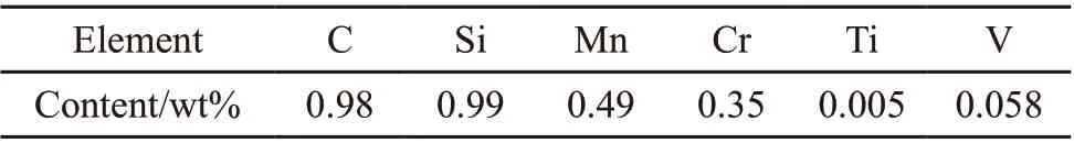
Table 1 Chemical composition of the steel materials used in this work
Both sets of wires, AD and GI wires, were subjected to the following mechanical tests. Tensile tests were performed on a universal material testing machine at a constant speed of 2 mm/min to obtain the data of tensile strength and reduction area (R.A.). According to the Chinese National Standard GB/T 239-1999, unidirectional torsion tests were conducted on a CTT1000 torsion testing machine, and specimens with a length of 700 mm were tested with a torsion velocity of 30 r/s. Mechanical tests under each condition were successfully repeated at least three times. For investigating the near-surface microstructure characterizations, TEM analysis was carried out by a JEOL JEM-2100F instrument operating at a voltage of 200 kV. TEM samples were ground to about 60 μm and thinned by twin-jet electro-polishing (Struers TenuPol-5) in glacial acetic acid of 10% HClO4at a temperature of 253 K and a voltage of 40 V. FIB-SEM was used to characterize the fracture surfaces of torsional failure, the near-surface microstructure of the longitudinal sections of AD wires etched in 4% nitric acid alcohol solution and the transverse sections of GI wires etched by the ion-beam.Thermal analysis was tested using differential scanning calorimetry (DSC) (NETZSCH STA449C) at a heating rate of 25 ℃/min in a flowing Ar atmosphere.
3 Results
3.1 Mechanical properties
Mechanical properties and torsion performance of the AD and GI wires are presented in Table 2. Compared the two groups of samples, both of the tensile strength of AD wires exceeded 2 100 MPa, and then decreased to 2 060 and 2 054 MPa after hot-dip galvanizing process, respectively, which have fallen about 2.6%. The reduction area and torsion performance are used to evaluate the toughness of wires. Initially, the reduction area and torsion circle of AD wires of the two groups had a similar result. After annealing in zinc bath at 450 ℃ for 60 seconds, both of the toughness of GI wires declined, especially for sample 1, the reduction area and torsion circle of sample 1-2 decreased rapidly from 43% to 5% and from 25 to 4, respectively. And in the torsion test, the fracture of sample 1-2 and 2-2 is respectively characterized as delaminated (Fig.1(a))and non-delaminated (Fig.1(b)). In order to satisfy security requirements, the torsion circle of GI wires usually need to be over 8 accompanied by non-delaminated fracture which implies torsion performance of wires is unqualified and qualified, respectively, for sample 1-2 and sample 2-2.
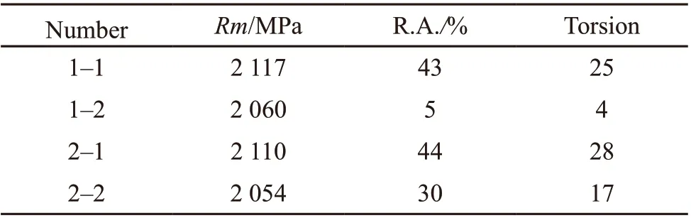
Table 2 Tensile and Torsion property of steel wire
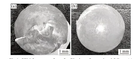
Fig.1 SEM fracture surfaces for GI wires after torsional failure: (a)sample 1-2; (b) sample 2-2
3.2 Near-surface microstructure
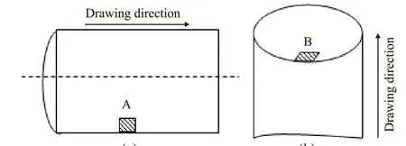
Fig.2 Schematic illustration for near-surface observation area of longitudinal section and transverse section: (a) AD wires; (b)GI wires.
Fig.2 is a schematic diagram illustrating the near-surface observation area of longitudinal section and transverse section, respectively, for AD and GI wires. The AD wires were cut in longitudinal axis to obtain samples, the samples were etched by 4% nitric acid alcohol solution after polishing, and area A(Fig.2(a)) was the area for microstructural observation.The GI wires were cut in transverse axis to obtain samples, after polishing the samples were etched by the ion-beam using FIB-SEM, and the longitudinal cutting area perpendicular to B (Fig.2(b)) was the area for microstructural observation.
Fig.3 shows the SEM images for near-surface microstructure of sample 1-1. The elongated pearlite colonies are almost turned to drawing direction and became a fiber structure, and similar results are also obtained in previous studies. It is interesting to note that there are some ribbonlike structures which are about 1 μm in width and more than 20 μm away from the surface of wires (Fig.3(a)). High magnified image of the ribbonlike structures (the rectangular area in Fig.3(a)) is presented in Fig.3(b). It can be seen that the ribbonlike structures consisted of a mass of submicron granular ferrite with grain size of about 400 nm accompanied by some particles in the ferrite matrix and boundary(indicated by the arrows in Fig.3(b)). As illustrated in Figs.3(c) and 3(d) (the rectangular area in Fig.3(c))which are within 20 μm from the interface, it shows that there are lots of cementite grains located in ex-cementite lamellae (indicated by the rectangular area in Fig.3(d)).
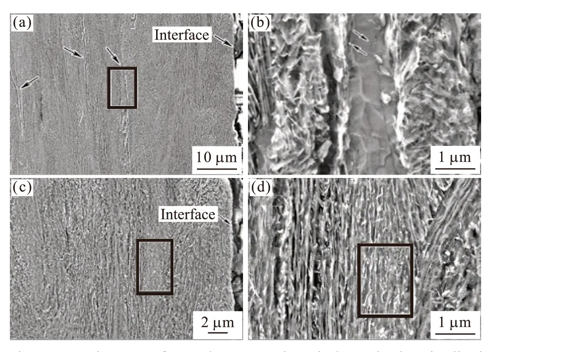
Fig.3 SEM images of sample 1-1 sectioned along the longitudinal direction: (a) and (c) near-surface microstructure; (b) high magnification of rectangle area in (a); (d) high magnification of rectangle area in (c)
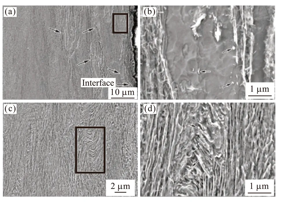
Fig.4 SEM images of sample 2-1 sectioned along the longitudinal direction: (a) and (c) near-surface microstructure; (b) high magnification of rectangle area in (a); (d) high magnification of rectangle area in (c).
Fig.4 shows the SEM images for near-surface microstructure of sample 2-1. Compared to sample 1-1,there are a greater number of ribbonlike structures in sample 2-1, and the ribbonlike structures located closer to the surface of wires, as shown in Fig.4(a). High magnified image of the ribbonlike structures (the rectangular area in Fig.4(a)) is presented in Fig.4(b). It can be seen that a large amount of submicron granular ferrite similarly included in the ribbonlike structures accompanied by some cementite particles in the ferrite matrix and boundary (indicated by the arrows in Fig.4(b)). As illustrated in Figs.4(c) and 4(d) (the rectangular area in Fig.4(c)), the bent cementite lamellae presented plastic deformation and a small amount of them are broken into globular cementite particles, and the pearlite lamellar structure could be basically distinguished which means that the layered structure has been retained to a certain degree.
The etch pits obtained by the ion beam presents that the interface between steel matrix and zinc coating is clear as indicated in Fig.5 and Fig.6 by the arrows.And the observation areas of GI wires were perpendicular to transverse sections (Fig.5(a) and Fig.6(a)),respectively, for sample 1-2 and sample 2-2. Without chemical etching, the microstructure etched by the ion beam was shown in Fig.5(b) and Fig.6(b). The lamellar structure of pearlite is clear and distinguishable, some cementite lamellae are broken (the circular region) and spheroidized (the rectangular area) in Fig.5(b), and the newly formed cementite particles are almost located in ex-cementite lamellae and seem to have undergone coalescence. Compared with sample 1-2, one interesting observation is that the lamellar structure completely disappears and is replaced with plenty of submicron granular ferrite with grain size of about 600 nm in Fig.6(b).
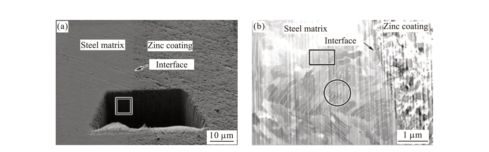
Fig.5 SEM images of sample 1-2 etched by the ion beam: (a) the etch pit; (b) high magnification of rectangle area in (a)
4 Discussion
Based on the observation of submicron granular ferrite on near-surface in this investigation, two interesting questions naturally arise: what is the mechanism for submicron granular ferrite on near-surface? And how do the submicron granular ferrite affect the torsion performance and mechanical properties. The two questions will be discussed in detail as follows.
4.1 Mechanism of near-surface ferrite formation
The mechanism of submicron granular ferrite formation was studied by TEM. Fig.7 shows microstructure features at different strains. The initial microstructures of the wire rod presents a typical but imperfect lamellar structure which is characterized by consisting of a few dislocation lines with a low dislocation density, as shown in Fig.7(a). After four stages of cold drawing process (ε=0.79), dislocations tangles are formed accompanied by dislocation density increase and single dislocation decrease, as shown in Fig.7(b). And these observations are in good agreement with the literature results that the newly generated dislocations nucleating from the ferrite-cementite interface intersect with original dislocations forming dislocations tangles[33,34]. With an increase in drawing strain (ε=1.42), it is observable that there existed the aforementioned ribbonlike structures in the AD wires consisting of sub-grains which could be attributed to dislocation rearrangement under a higher dislocation density, as marked by arrows in Fig.7(c). Simultaneously, the lamellar structure partially ruptures and breaks into cementite particles, and the inter-lamella spacing significantly decreases to approximately 100 nm accompanied by the thickness reduction of cementite lamellae, as shown in Fig.7(d).Some prominent changes occurred in the microstructural morphology after being galvanized, and the dislocation structures transformed from sub-grains to submicron granular ferrite by recovery process of ferrite, as marked by arrows in Fig.7(e). And cementite particles appear coarser than as-drawn wires and seem to have undergone spheroidization accompanied by lamellar structure disappearing, as marked by arrows in Fig.7(f).And the granular ferrite formation regions have been supposed to undergo more deformation, to achieve dislocation rearrangement forming more complex dislocation patterns,i e, submicron granular ferrite. So, their distribution can suggest homogeneousness of deformation degree to a certain extent.
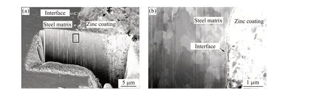
Fig.6 SEM images of sample 2-2 etched by the ion beam: (a) the etch pit; (b) high magnification of rectangle area in (a)
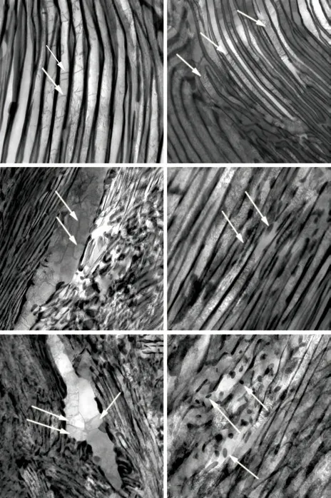
Fig.7 TEM images of pearlitic microstructure at different strain conditions: (a) ε=0; (b) ε=0.79; (c) and (d) for the AD wires;(e) and (f) for the GI wires.
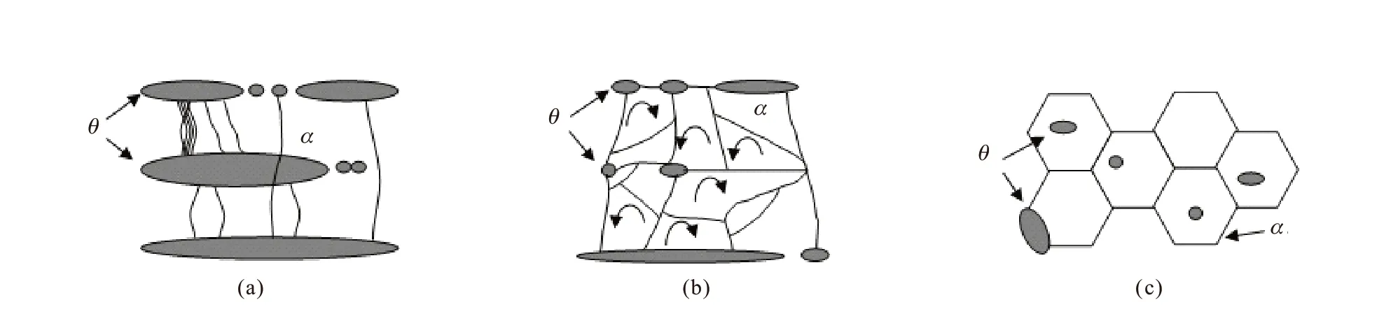
Fig.8 Schematic diagrams of the evolution of submicron granular ferrite during cold drawing and galvanizing process (θ: cementite, α:ferrite): (a) Lots of dislocations are generated during cold drawing; (b) Sub-grain boundaries are formed and rotated to be high angle grain boundaries; (c) Submicron granular ferrite is formed by recrystallization.
Based on the above discussion, a schematic diagram illustrating the mechanism of submicron granular ferrite formation on near-surface is presented in Fig.8:in the initial stages of cold drawing, there are lots of dislocations generating accompanied by the fragmentation of cementite lamellar, as shown in Fig.8(a).And previous study[33,34]predicted recently that the generating dislocations can drag out carbon atoms in cementite lamellar, even crossing through the lamellar,which could accelerate the cementite decomposition.These evolutions continue with an increase in drawing strain, the cementite layers completely rupture and break into cementite particles located in ex-cementite lamellae, and the dislocation structures turn from dislocation lines and tangles into sub-grains by dislocation rearrangement, as shown in Fig.8(b). As cold drawing and galvanizing process proceed, the high angle grain boundaries form, leading to the formation of submicron granular ferrite accompanied by cementite re-precipitation in carbon saturated ferrite, as shown in Fig.8(c).
4.2 The infulence of near-surface microstructure on mechanical properties
To cold-drawn pearlite steel wires, the microstructure evolution and its effect on the mechanical properties have been deeply investigated: during the cold drawing process, the lamellar pearlitic structure becomes thin and aligned with the wire axis, accompanied by reduction of interlamellar spacing, dislocation density increase, texture formation, cementite lamella deformation and decomposition and reprecipitation. In addition, pearlite steel wires could store energy during cold drawing, leading to be sensitive to heat treatment like galvanized process.
Corresponding to the above microstructure evolution, the strengthening mechanisms of cold-drawn pearlite steel wires have four types, respectively for boundary strengthening, dislocation strengthening,<110> texture strengthening and solid solution hardening. And previous studies[35,36]pointed out that during cold drawing, boundary strengthening and dislocation strengthening are the predominant strengthening mechanism at strain <1.5, and the phenomenon of cementite decomposition occurs at strain >1.5. Under the same cold strain at 1.42, both of the two AD wires present fiber structures, and most of lamella structure toward the drawing direction accompanied by the reduction of pearlite lamellar spacing, increase of dislocation density, cementite deformation, as shown in Figs.7(a)-(d). And the relationship between microstructure and mechanical properties in AD wires can be illuminated by the Hall-Petch relation, which can explain the data of Table 2 that both of two AD wires have similar excellent strength and a reasonable level of toughness.Comparing between sample 1-1 and sample 2-1, most regions but near-surface have no appreciable differences in microstructure. Fig.3 and Fig.4 show that the deformation of cementite lamellae and zonal distribution of submicron granular ferrite are notably different in near-surface. In sample 1-1, the banded structure distribution is more than 20 μm away from the interface and a partial of cementite lamellae is destroied. By comparison, there are more banded structures which are located closer to the interface in sample 2-1, and kept the cementite lamellae to a certain degree. After hot-dip galvanizing process, TEM analysis reveals that some changes in the microstructure occur. The dislocation structures transform from sub-grains to submicron granular ferrite by recovery process accompanied by decrease of dislocation density, and portions of cementite lamella are difficult to distinguish (Figs.7(e)-7(f)).The cementite decomposition which causes carbon atoms to diffuse to ferrite regions is considered to be the main reason for the loss of steel ductility[11]. This can explain the decrease in ductility of GI wires after hot-dip galvanizing process, as shown in Table 2. In comparison with sample 2-2, sample 1-2 has a bigger decline in reduction area and torsion performance probably because the cementite lamellae are less fragmented but also less dissolved in sample 2-2.
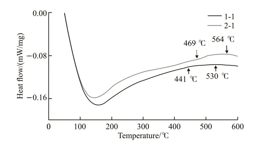
Fig.9 DSC curves of AD wires (sample 1-1 and sample 2-1)obtained at a heating rate of 25 ℃/min
Fig.9 shows the DSC curve of AD wires to evaluate thermal stability of cold-drawn wires during galvanizing process. For both of the two samples, a broad exothermic peak appears over a temperature range from about 440 to 570 ℃ near the galvanizing temperature(450 ℃). This peak might correspond to cementite re-precipitation[37]and spheroidization of lamellar cementite in cold drawn wires[38]. The exothermic peak temperature range for sample 1-1 is from about 441 to 530 ℃, while for the sample 2-1 is from about 469 to 564 ℃ which exceeds the galvanizing temperature(450 ℃). Wires can store deformation energy during cold drawing process to act as the driving force for cementite decomposition. By comparison, Fig.9 suggests that the deformation of sample 1-1 is greater than sample 2-1 which is consistent with microstructure observation, and this may explain the difference of mechanical properties between sample 1-2 and sample 2-2:under galvanizing temperature (450 ℃), cementite decomposition occurs more obviously in sample 1-2, just causing more carbon atoms to diffuse to ferrite regions,leading to brittleness of steel. And it also reveals that sample 2-2 has a higher thermal stability, as compared to sample 1-2.
Ideally, the closer to the surface of wires, the bigger deformation, and the granular ferrite is supposed to form in the biggest deformation regions. Therefore,their distribution can suggest homogeneousness of deformation degree to a certain extent. Through the distribution of submicron granular ferrite as shown in Fig.3 and Fig.4, it reveals that sample 2-1 has a more homogeneous deformation during cold drawing, as compared to sample 1-1. In addition, the granular ferrite which serve as a soft phase in microstructure first generates the torsional crack during the torsion test, can relax the stress on the crack tip, making the crack propagation paths to bend or fork, and improving crack propagation resistance[39]. In accordance with torsional stress distribution, the submicron granular ferrite which is located closer to the surface of wires is beneficial to enhance coordination deformation ability. And the submicron granular ferrite which is away from the interface, is expected to be crack source during the torsion test, which is consistent with the fact that most of the unqualified torsional fractures present a split phenomenon and the cracks originate from the inside of the wire rather than the surface with maximum shear stress[8],i e, sample 1.According to the above analysis, the mechanical properties especially for torsion performance of cold-drawn wires are primarily related to both of the thermal stability of the cementite layer and distribution of granular ferrite.
5 Conclusions
a) The tensile strength, reduction area and torsion ability of cold-drawn pearlitic steel wires declines after hot-dip galvanizing process, and the tensile strength is independent of the toughness value of the wires(ε=1.42). Sample 1-2 and sample 2-2 with similar tensile strength before and after hot-dip galvanizing process, are respectively characterized as delaminated and non-delaminated in torsion test, accompanied by huge differences in toughness value (i e, reduction area and torsion ability) after hot-dip galvanizing process.
b) There exists submicron granular ferrite on near-surface of the wires (ε=1.42), which could be attributed to dislocation rearrangement and sub-grains rotation during cold drawing and hot-dip galvanizing process,i e, submicron granular ferrite. The granular ferrite is supposed to form in the biggest deformation regions, so their distribution can suggest homogeneousness of deformation degree to a certain extent:the closer to the surface of their distribution, the more homogeneous deformation of the wires.
c) The torsion performance of cold-drawn wires is primarily related to both of the thermal stability of the cementite layer and distribution of granular ferrite: the sample which has more obvious cementite decomposition under galvanizing temperature (450 ℃), just causes more carbon atoms to diffuse to ferrite regions leading to brittleness of steel; additionally, the submicron granular ferrite which is located closer to the surface is beneficial to enhance the microstructure coordination deformation ability, consistent with the fact that most of the unqualified torsional fractures present delamination and the cracks originate from the inside of the wire rather than the surface with maximum shear stress.
杂志排行

Journal of Wuhan University of Technology(Materials Science Edition)的其它文章
- Preparation and Performance of Graphene Oxide Modified Polyurethane Thermal Conductive Insulating Adhesive
- Effect of Polymer Network Morphology on the Performance of Polymer Dispersed Liquid Crystal (PDLC) Composite Films
- Preparation of Controllable Cross-Linking Polyethylene Foaming Materials and Their Properties
- Enhanced Thermoelectric and Mechanical Properties of p-type Bi0.5Sb1.5Te3 Bulk Alloys by Composite Electroless Plating with Ni&Cu
- Fatigue Behavior of a Dissimilar Aluminum Alloy Welding Joint With and Without Natural Defect
- Effects of Varying Copper Content on the Microstructure and Mechanical Properties of FeCoNiCux