Three-dimensional gravity inversion based on optimization processing from edge detection
2022-09-05ShengLiuShuanggenJinQiangChen
Sheng Liu , Shuanggen Jin , Qiang Chen
a Xinjiang Astronomical Observatory, Chinese Academy of Sciences, Urumqi 830011, China
b University of Chinese Academy of Sciences, Beijing 100049, China
c Shanghai Astronomical Observatory, Chinese Academy of Sciences, Shanghai 200030, China
d School of Remote Sensing and Geomatics Engineering, Nanjing University of Information Science and Technology, Nanjing 210044, China
Keywords:Gravity inversion Locally weighted constraint Petrophysical constrain Fuzzy c-means clustering algorithm OpenAcc technology
ABSTRACT Gravity inversion requires much computation, and inversion results are often non-unique. The first problem is often due to the large number of grid cells. Edge detection method, i.e., tilt angle method of analytical signal amplitude (TAS), helps to identify the boundaries of underground geological anomalies at different depths, which can be used to optimize the grid and reduce the number of grid cells. The requirement of smooth inversion is that the boundaries of the meshing area should be continuous rather than jagged. In this paper, the optimized meshing strategy is improved, and the optimized meshing region obtained by the TAS is changed to a regular region to facilitate the smooth inversion. For the second problem, certain constraints can be used to improve the accuracy of inversion. The results of analytic signal amplitude (ASA) are used to delineate the central distribution of geological bodies. We propose a new method using the results of ASA to perform local constraints to reduce the nonuniqueness of inversion. The guided fuzzy c-means (FCM) clustering algorithm combined with priori petrophysical information is also used to reduce the non-uniqueness of gravity inversion. The OpenAcc technology is carried out to speed up the computation for parallelizing the serial program on GPU. In general,the TAS is used to reduce the number of grid cells. The local weighting and priori petrophysical constraint are used in conjunction with the FCM algorithm during the inversion, which improves the accuracy of inversion. The inversion is accelerated by the OpenAcc technology on GPU. The proposed method is validated using synthetic data,and the results show that the efficiency and accuracy of gravity inversion are greatly improved by using the proposed method.
1. Introduction
Inversion algorithms are essential tools in geophysical exploration. They can be used to process geophysical data and related geophysical information, thus giving us underground physical property models. However, the inversion process requires a huge amount of computation, and the inversion results are not always unique. The first problem is often caused by the large number of underground meshing units. In general, the entire work area is always divided into a plurality of congruent cuboid assemblies[1-6]. There are various other meshing methods, for example, using grids that gradually extend with increasing depth [7], hybrid grids [8], octree grids [9], and unstructured tetrahedral meshes[10]. Although these ways reduce the number of grid cells, the number of grid cells remains large.
To further reduce the number of grids, Yang et al. proposed to use the edge detection results for this purpose [11]. Many numerical algorithms were developed for the edge detection, including first-order vertical derivative (VDR) [12], tilt angle [13], analytic signal amplitude (ASA) [14], total horizontal derivative (THDR)[15,16].Normalized total horizontal derivative method(NTDT)[17],tilt angle of analytical signal amplitude(TAS)[18],analytical signal mode method for tilt angle (ASTA) [19], and normalized standard deviation method(NSTD)[20].Ying et al.verified the effectiveness of the aforementioned methods[21].It is considered that the TAS is less affected by the change of the buried depths of the geological bodies,and the prominent boundary is complete and clearer,which is a better method among the above methods. Additionally, the calculation process of the TAS is relatively simple, and the maximum value of the calculation result can represent the edges of the subsurface anomaly features. When using the TAS method for edge detection,the vertical derivative of the ASA value needs to be calculated.There are many ways to calculate this vertical derivative,such as the frequency domain technique[22],the finite-difference algorithm[23],and the direct expression[18].In this paper,the TAS is used to reduce the number of mesh cells, and the frequency domain technique is contained in the computing process of the TAS.
The inverted results from smooth inversion [1,2] always reflect the spatial distribution contours of geological bodies.In the smooth inversion method, it is indispensable to perform finite difference processing on the smooth constraint.The finite difference requires that the boundaries of the meshing region should be continuous,and there are no discrete points in the whole working area.Therefore, the smooth inversion is performed on a regular rectangular area[1-6].It is not easy to execute finite difference with the meshing area holding a complicated boundary.Additionally,it will also cause difficulties for subsequent processing,such as calculating the coordinates of grid cells. In this paper, we propose a new method to process the meshing area delineated by the edge detection of TAS, so that the irregular meshing area can became a regularized region, making the finite difference processing convenient and straightforward.
For solving the second problem of non-uniqueness of inversion results, geological constraints are added to geophysical inversion[24-28]. Therefore, it's necessary to constrain the geophysical inversions with priori information from geology, which significantly decreases the non-uniqueness of inversion results.
The reference model is often set to 0 g/cc. The strategy of optimized meshing is to obtain larger distribution area than the spatial distribution of the real model,and the densities of the excess region should be low values. However, due to the non-uniqueness of the inversion, the physical values of this part are always not zero. To reduce the non-uniqueness, it is necessary to impose local constraints on this area.As the depth of the geological body increases,the value of ASA will be concentrated at the centers of the anomalous bodies on the horizontal plane[29].In this paper,we propose a strategy based on optimizing the local weighting matrix wsof a smooth inversion method by using the results of the ASA of the gravity anomalies.
A strategy of the guided FCM clustering algorithm was proposed to add physical property constraints to the inversion [30-33].Consequently, using this methodology for inversion, the values of model are well clustered to a priori petrophysical information,which further reduces the non-uniqueness of geophysical inversion.
In gravity inversion, the efficiency is also a crucial aspect. It is necessary to parallelize serial programs by GPU acceleration technology [34-38]. The OpenAcc technology is characterized by simple and rapid program development, which can fully use GPU computing resources.In this paper,the OpenAcc technology is used to implement parallelization on the GPU to speed up the calculation of gravity inversion.
The proposed method applies the optimized meshing, local weighting,and the guided FCM algorithm.For the first part,gravity anomaly data is processed using the TAS method. The results are used for the optimized meshing, which reduces the number of mesh cells. Then, ASA values with obtained geologic body center features are used for optimizing local weighting matrix wsto reduce the non-uniqueness. Next, the guided FCM algorithm combined with priori petrophysical information is used to perform 3D gravity inversion.
2. Methodology
In this paper, the edge detection methods are selected to optimize the field inversion. The guided FCM clustering algorithm is incorporated into a Tikhonov regularized inversion with scattered priori petrophysical property information.The OpenAcc technology can perform high-performance computing on GPU to improve inversion efficiency. In this section, those mentioned components will be introduced.
2.1. General methodology of smooth inversion
The objective function of the traditional regularization inversion is as follows [1,2]:

where the matrix m represents density model;mrefis the reference model; ws, wx, wyand wzare spatially dependent weighting functions; αs, αx,αyand αzare coefficients; and w(z) is the depthweighting function.
Eq.(2)contains first-order partial differential equations that can be processed using a finite difference theory. Generally, the finite difference processing is performed for the first-order differential equations by any kind of difference scheme,and the grid difference processing cannot be performed at isolated points [39].
2.2. Reducing the number of mesh cells
The steps for reducing the number of mesh cells will be explained in the following sections, including step A derived from[40],and steps B to D based on step A.In this paper,the optimized meshing algorithm firstly proposed by[11]is improved to facilitate the smooth-inversion method.
A. Calculating the ASA of the potential field data according to[14]:


2.3. Adding optimized local constraint
In the model objective function shown in Eq. (2), the petrophysical property values of a reference model can be used together with a set of weight coefficients ws. These weighting coefficients indicate the confidence level of physical values of rectangular elements.The bigger value of ws,the higher confidence level as the suitable physical value of this unit [1,2,41].
In this paper, a certain strategy can be adopted to optimize the weighting matrix wsusing the results of the ASA.The details of this method are displayed in the following steps:

where the threshold is also a constant within [0,1]. Generally, the ASA method can't balance various geological anomalous bodies with different depths.The shallow geological anomalies calculated by the ASA method tend to have larger values, while the deeper geological bodies have smaller values. Therefore, an appropriate threshold value must be selected to consider all geological anomalous bodies with different depths.In general,the values of ASA in the entire work area contain multiple data-aggregation areas. In this paper, the smallest value at the edge of the area is divided by the maximum value of the entire work area as the threshold value.
D. Using the results obtained from step C, the grids with four corner points (equal to 1.0) are separated from the observation network. Then, the obtained area is expanded from 2D to 3D. As a result, the optimized meshing region can be divided into two parts. Zone 1 is the most likely area where the geological body exists, and zone 2 is the area where the geological body is less likely to exist.
According to the results of step D, it can be considered that a confidence criterion for a reference model has been obtained. The physical property values of the individual elements of the reference model can be described by their corresponding elements of the parameter matrix ws.Here,we adopted the reference model of 0 g/cc. In a region where the geological body is unlikely to exist, the density value is most likely to be 0 g/cc,thus giving a larger value to the corresponding element in the matrix ws.In contrast,in a region where the geological body is highly likely to exist, its physical property value is often not 0 g/cc,thus giving a smaller value for the corresponding element in this region.
In Fig. 2, a strategy is added to the above-mentioned local weighting. In region 1, the larger the ASA value, the more concentrated the physical property value is at this position on the horizontal plane,so it is necessary to highlight this region based on the local weighting.The strategy is to add the ASA values of the closest four points of each cell and then obtain the average value. Then,traversing all cells of the first layer based on optimized meshing,normalizing all values and getting their opposite values.The results obtained from step D show that the region with larger ASA values corresponds to smaller values of the corresponding element ws,and the part with smaller ASA values corresponds to larger values.Next,we multiply the obtained value with the local weighted value to get the final local weighted matrix in zone 1. In summary, by adopting the suitable threshold, a method of applying local constraints to a reference model, i.e., assigning different values to the elements of the weighting matrix ws, is established based on the optimized meshing and the central recognition of field data.All the details are shown in Fig. 2.

Fig. 1. The workflow diagram for optimizing meshing. There are two parts in the process. The first part optimizes the spatial extent of meshing by TAS, and the second part generates the regularized meshing area based on the first part.
When the geological bodies are shallow, the calculated ASA values may not gather at the centers of geological bodies,but at the edges.In this case,it is not appropriate to use the ASA value for the above-mentioned local weighting. Gravity anomalies have good spatial correspondence with underground geological bodies, so they can also be chosen for local weighting instead of ASA.Generally, ASA has better convergence than gravity anomaly, and its recognition effect is better, so it is better to use ASA values for local weighting. However, the ASA method is an edge detector method. When the geological bodies are shallow, the ASA values are located at the boundaries of the geological bodies.Obviously,it is not suitable to use the ASA method for local weighting.Therefore,we firstly perform ASA processing on the gravity anomaly. When the ASA result is not concentrated in the centers of geological bodies, we can directly perform the local weighting processing by the above method.It should be noted that the absolute values of the gravity anomaly need to be calculated for local weighting. The aforementioned strategy can effectively avoid the situation that the ASA values cannot be used for local weighting due to the existence of shallow geologic bodies.
2.4. Gravity inversion based on guided FCM clustering algorithm
The guided FCM clustering inversion is formulated by adding the FCM clustering term to a classic regularization-inversion method. The objective function [30-33,42] is as follows:
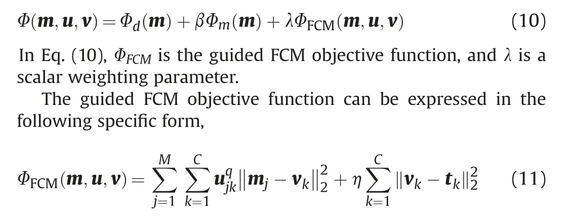
where M is the number of model cells, ujkmeasures the degree of the jthmodel cell belonging to the kthcluster,q is the fuzzy factor,C is the number of cluster categories,vkis the cluster center,tkis the target cluster center, and η is the weighting parameter.
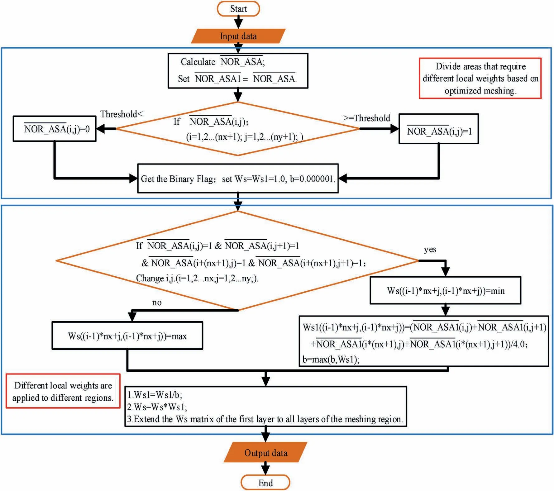
Fig.2. The workflow diagram for local weighting.There are two parts in the process.The first part is used to divide the local weighted area into different values,and the second part is to assign the value to the local weighting matrix ws. Max and min represent the larger and smaller values for the local weighting.
The FCM method based on smooth inversion is an unsupervised learning method, and its clustering effect is dependent on the distribution of the initial model's values. Generally, the initial model obtained by the smooth inversion has a wide range of physical property values, which causes different categories to be chaotic in the clustering process. For example, according to the physical priori information, the entire working area contains multiple types of physical property values.Generally,the initial model obtained by the smooth inversion may have equal values in different parts of the work area, but the actual physical property values are different in these parts. Therefore, it is difficult to accurately classify these data based on the magnitude of the petrophysical property.
Li and Sun[42]proposed a method that adds a weighting matrix in the guided FCM term to consider different regions with different target cluster centers, which avoids the confusion of clustering effect based on the reference model from smooth inversion. The corresponding formula is as follows:

where N is the number of regions with different target cluster centers according to the geological priori information, γljcan be take on values of one or zero, and uljk, vlk, tlkare clustering parameters in different regions.
We use the iterative minimization algorithm to minimize the objective function in Eq.(10)[42],and the corresponding details are shown in algorithm 1.
2.5. Parallel analysis of forward and inversion based on OpenAcc technology
The parallelization of computation is achieved using the OpenAcc technology. The grammar of OpenAcc is that serial programs can be parallelized by adding several simple guided language statements without modifying the original source codes.Analyzing the whole process of inversion in Fig. 3, the forward matrix,matrix operations after minimizing the objective function,and inversion iterations consume a lot of computing resources.We applied the gauss newton method for inversion and conjugate gradient (CG) algorithm for solving the subproblem. The pseudocode of CG is shown in algorithm 2. The calculations before the iteration mainly include the forward matrix G, the weighting matrix Wm,and the gradient g0of the objective function.Then,in each iteration of algorithm 2, vectors Pk, qk, density matrix m,gradient matrix gk, and variable values of βkand akare mainly included. The matrices computations mentioned in the last two sentences all need a large amount of calculation,so it is vital to use OpenAcc technology for GPU acceleration.
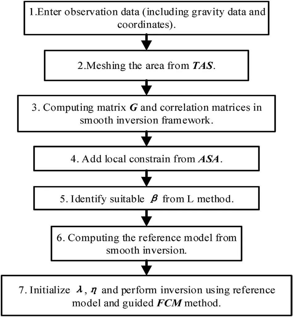
Fig. 3. Description of the total workflow of gravity inversion in this paper.
When performing a specific analysis,the number of rows of the matrix G is the total number of the field data M, and the corresponding number of columns is the total number of the meshing units N.The number of elements of the matrix Wmis N*N.In the inversion process, the matrices G1and d1of algorithm 1 have a multiplication of the matrices G and Wm.In the CG algorithm,the updates of the matrices gkand qkhave the operation of multiplying the matrix G and other vectors.Then, the calculation of ak,βkand mkis the addition, subtraction, or dot multiplication, and the calculation time is short. In general, calculations between large matrices use nested DO loops, and the OpenAcc technology can be used to accelerate the calculation of those nested loops.
For example,the pseudo-code of the parallelization calculation of the matrix G is enumerated as follows:
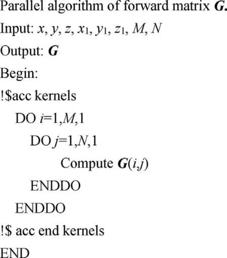
where x,y,and z are the coordinates of the meshing cells,and x1,y1,and z1are the coordinates of the ground net.Then,the calculations of the matrices Wm,G1,D1,gk,and qkcan follow the above example to perform a parallelization processing of multiple DO loops.From the above analysis, a total inversion process is displayed in Fig. 3.
3. Results and validation
To validate the proposed method for gravity inversion,we carry out several inversions using synthetic data.
3.1. First model
This model contains two geological bodies (see Table 1 for model details). A depiction of model 1 is shown in Fig. 4a. The gravity data computed from this model is shown in Fig.4b.Random noise with amplitude equal to 2%of the maximum data amplitude is added to the gravity anomaly. The gravity data conform to a regular grid of 31×31 data points,with a total of 961 equally spaced data points.Fig.4c and 4d represented the result of the TAS and the ASA computed from gravity anomaly data, respectively. In the inversion,there are 15 layers in the depth from 0 to 150 m(Fig.4e),and the size of each cell is set to be 10×10×10 m.

Table 1 The parameters for the geological bodies in the synthetic models.
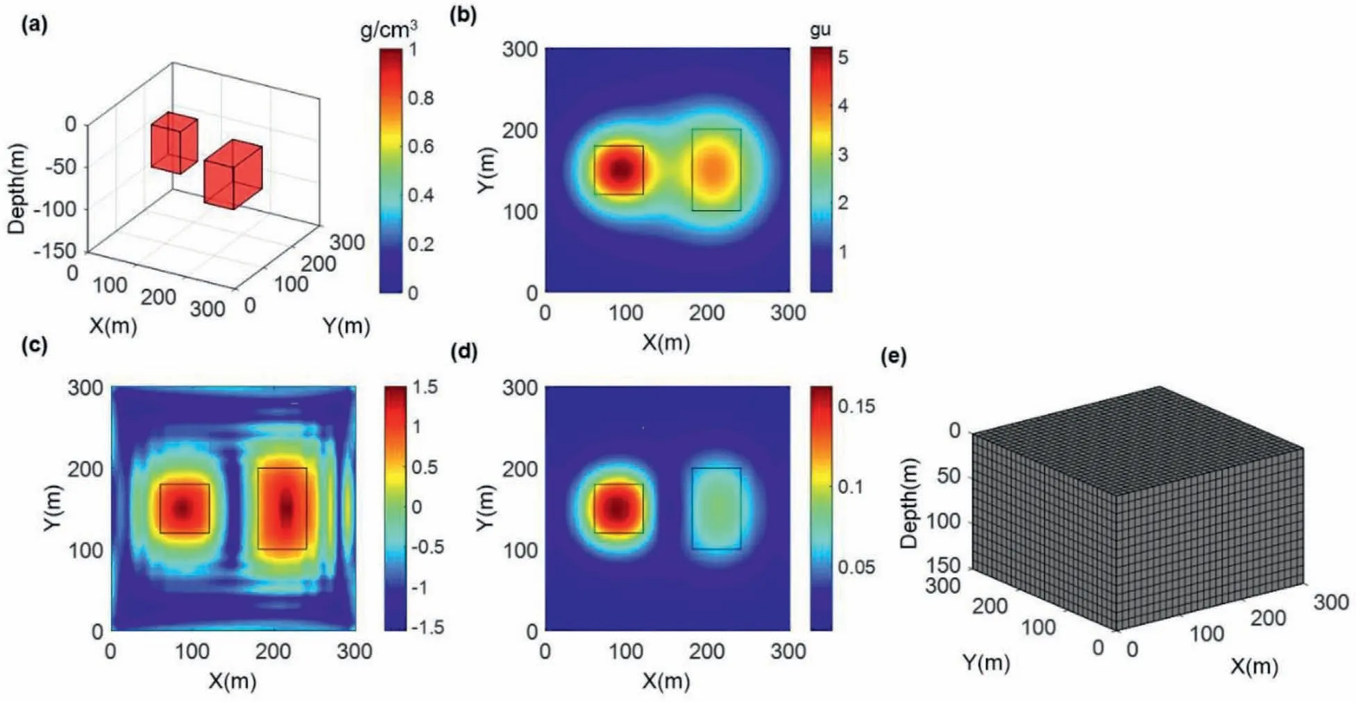
Fig. 4. (a) Spatial location of synthetic model 1. (b) The contour map of forward gravity anomaly of model 1 adding Gaussian noise. The results of (c) the TAS and (d) ASA of the gravity anomaly. The black lines outline the spatial extent of the source bodies on the horizontal plane. (e) A map of the original meshing.
It can be seen from Fig. 4c that the TAS data can obtain the boundaries of anomalous bodies with different depths, and the values of different regions are relatively close.Then,using the value of the green area divided by the maximum value of Fig.4c,we can obtain the optimized meshing parameter of 0.1.Fig.4d shows that the ASA data obtained from geological anomalous bodies at different depths vary greatly. The ASA values calculated from deeper anomalous geologic bodies are located at smaller values,and shallower anomalous geologic bodies are calculated at larger values.The parameter of local weighting can be obtained using the strategy mentioned in section 2.3. Thus, the value of the local weighted parameters is set to 0.3.
Fig. 5a shows the distribution on the horizontal plane after optimized meshing using the results of TAS.It can be found that its boundaries are irregular. To facilitate the finite difference of the smooth inversion, the curved edge of Fig. 5a is transformed into a regularized region shown in Fig. 5b. Then, extending 2D results to 3D,Fig.5c shows the corresponding results of optimized meshing.As shown in Table 2, the original 13500 grid cells are reduced to 5040 grid cells.
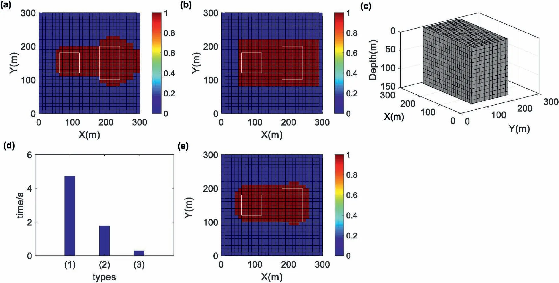
Fig.5. The display of the meshing results using the TAS with 0.1 as the optimized meshing parameter.The portion of the optimized meshing with red color is changed from(a)the area with curved edges to(b)the area with regular shape.(c)A 3D optimizing meshing map from TAS.(d)Forward time under different types:(1)represents the forward time in original meshing;(2)represents the forward time under the optimizing meshing;(3)represents the forward time under the optimized meshing using OpenAcc technology.(e)The results from the ASA with 0.3 as the local weighting parameter on the horizontal plane.
The amount of forward time is used to illustrate the effect of accelerated calculation by the optimized meshing and the OpenAcc technology. Fig. 5d shows the forward time in different situations.The first forward is obtained from a serial program based on the original meshing,using a time of 4.751 s.The second type is based on the original meshing,using a time of 1.786 s.The last forward is based on the optimized meshing and using the OpenAcc technology,with the time of 0.280 s.The time of the forward operations is reduced considerably in turn.Similarly,the calculation time of the matrix Wm, G1, d1, gk, and qkcould be greatly reduced in the subsequent process due to the use of optimized meshing and the OpenAcc technology. Fig. 5e shows a locally weighted region obtained by the results of ASA. The specific local weighting strategy used in the scheme is shown in Fig. 2. The maximum value is 200 and the minimum value is 2.0, and both values can be adjusted.
Next, the original regularization inversion is performed based on the optimized meshing. The slices of density distribution at different depths are shown in Fig. 6. The regularized inversion is conducted using the local weighting and optimized meshing, and Fig. 7 shows the inversion results of each layer. A comparison between Figs.7 and 6 shows that the results from the latter inversion are better.The physical property distribution is more concentrated,and the physical property difference is larger.At the same time,the boundary between geological bodies is more obvious after the inversion using the local weighting, and the distribution of its physical properties on the XY plane is more corresponding to the model distribution. The above results show the correctness of the strategy of the local weighting.
Then, the FCM inversion is conducted based on the referenced model from smooth inversion using the local weighting and optimized meshing. From Fig. 4a, we set the number of regions with different target cluster centers to 1 and C to 2. The target cluster centers are 0 g/cc and 1.0 g/cc. We set the weighting parameters γlj(l=1,2...N,j=1,2...M)equal to 1.Fig.8 shows the results of the various layers of FCM inversion.From the comparison of Figs.6-8,we can find that the results obtained by FCM inversion using the local constraint and priori petrophysical constraint are closer to the original model shown in Fig.4a,both in the spatial distribution andthe magnitude of the inverted physical properties. Next, we use more complex examples to verify the correctness of the proposed algorithm.

Table 2 The number of meshing cells and the original meshing cells in different synthetic models using different parameter pairs.

Fig.6. The results of performing the regularization inversion with the parameter(0.1)based on optimized meshing.The inversion results where z equals(a)5 m,(b)15 m,(c)25 m,(d)35 m,(e)45 m,(f)55 m,(g)65 m,(h)75 m,(i)85 m,(j)95 m,(k)105 m,(l)115 m,(m)125 m,(n)135 m and(o)145 m.(p)The Cartesian coordinates.(a)-(o)are consistent with the directions and length units shown in (p).
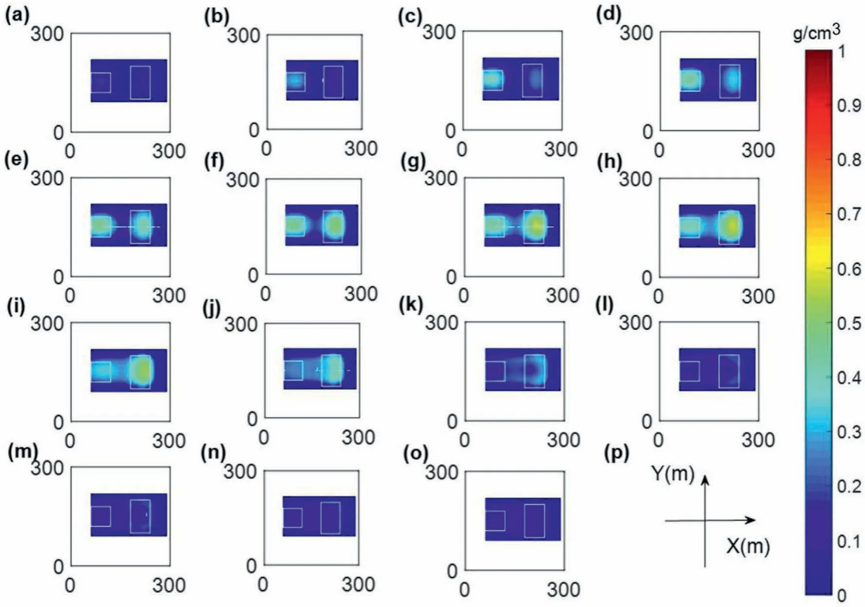
Fig.7. The results from the regularization inversion with the parameter pair(0.1,0.3)based on optimized meshing and local weighting.The inversion results where z equals(a)5 m,(b)15 m,(c)25 m,(d)35 m,(e)45 m,(f)55 m,(g)65 m,(h)75 m,(i)85 m,(j)95 m,(k)105 m,(l)115 m,(m)125 m,(n)135 m and(o)145 m.(p)The Cartesian coordinates.(a)-(o)are consistent with the directions and length units shown in (p).

Fig.8. The results of performing the FCM inversionwith the parameter pair(0.1,0.3).The inversion results where z equals(a)5 m,(b)15 m,(c)25 m,(d)35 m,(e)45 m,(f)55 m,(g)65 m,(h)75 m,(i)85 m,(j)95 m,(k)105 m,(l)115 m,(m)125 m,(n)135 m and(o)145 m.(p)The Cartesian coordinates.(a)-(o)are consistent with the directions and length units shown in(p).
3.2. Second model
Then,examples of anomalous bodies with different depths and densities are used to further test.A depiction of model 2 is shown in Fig. 9a. The gravity data computed from this model is shown in Fig. 9b. The random noise with an amplitude equal to 2% of the maximum data amplitude is also added to the gravity anomaly.Fig. 9c and 9d represented the TAS and ASA, respectively. Model 2 has the same original meshing as model 1.Details can also be found in Table 1 and Table 2.
A similar method is used in the first model to search for the optimized meshing and local weighted parameter. Thus, values of the optimized meshing and local weighted parameters are set to 0.1 and 0.3, respectively. Fig.10a shows the distribution on the horizontal plane after the optimized meshing using the results of TAS.This distribution is also transformed into the regularized result shown in Fig.10b. Fig.10c depicts the 3D meshing cells based on optimized meshing. As can be seen in Table 2, the original 13500 grid cells are reduced to 5760. This result can also prove the correctness and effectiveness of the optimized meshing.
Fig. 10d shows the forward time in different situations. The forward types are the same as the types in Fig. 5d. The corresponding forward time is 2.032 s and 0.289 s, respectively. The forward time based on the OpenAcc technology dramatically decreases. Similarly, the other calculation time during the inversion process is also significantly reduced. Fig. 10e shows a locally weighted region obtained by the results of ASA in red color. In this model, the maximum value is 300, and the minimum value is 20.
The slices of density distribution of regularized inversion at different depths of model 2 are shown in Fig.11. Then, the regularized inversion is performed using local weighting and optimized meshing. Fig. 12 shows the inversion results for each layer. From Figs.12 and 11,we find that the results from the latter inversion are better,the physical property distribution is more concentrated,and the physical property difference is larger.
According to Fig.9a,we set the number of regions with different target cluster centers equal to 2. The first region's target cluster centers are 0 g/cc and 0.5 g/cc, and the second region's target cluster centers are 0 g/cc and 1.0 g/cc,respectively.Then,we set the weighting parameters γlj(l=1,2...N,j=1,2...M) of different regions and cells.The FCM inversion is performed based on the local weighting and optimized meshing.Fig.13 shows the results of the various layers of FCM inversion. Comparing Figs. 11-13, we find that the results obtained by FCM inversion using local and physical constraints are closer to the original model shown in Fig.9a,both in the spatial distribution and the magnitude of inverted physical properties.Next,a more complicated example is used to verify the advantages of the proposed method.
3.3. Third model
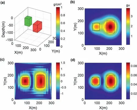
Fig. 9. (a) Spatial location of model 2. (b) The contour map of forward gravity anomaly of synthetic model 2 adding Gaussian noise. The results of (c) the TAS and (d) ASA of the gravity data.

Fig.10. The meshing results using the TAS with 0.1 as the optimized meshing parameter.The portion of the optimized meshing with red color is changed from(a)the area with curved edges to(b)the area with regular shape.(c)A 3D optimizing meshing map from TAS.(d)Forward time under different types:(2)the forward time under the optimizing meshing;(3)the forward time under the optimized meshing using OpenAcc technology.(e)The results using the ASA with 0.3 as the local weighting parameter is displayed on the horizontal plane.
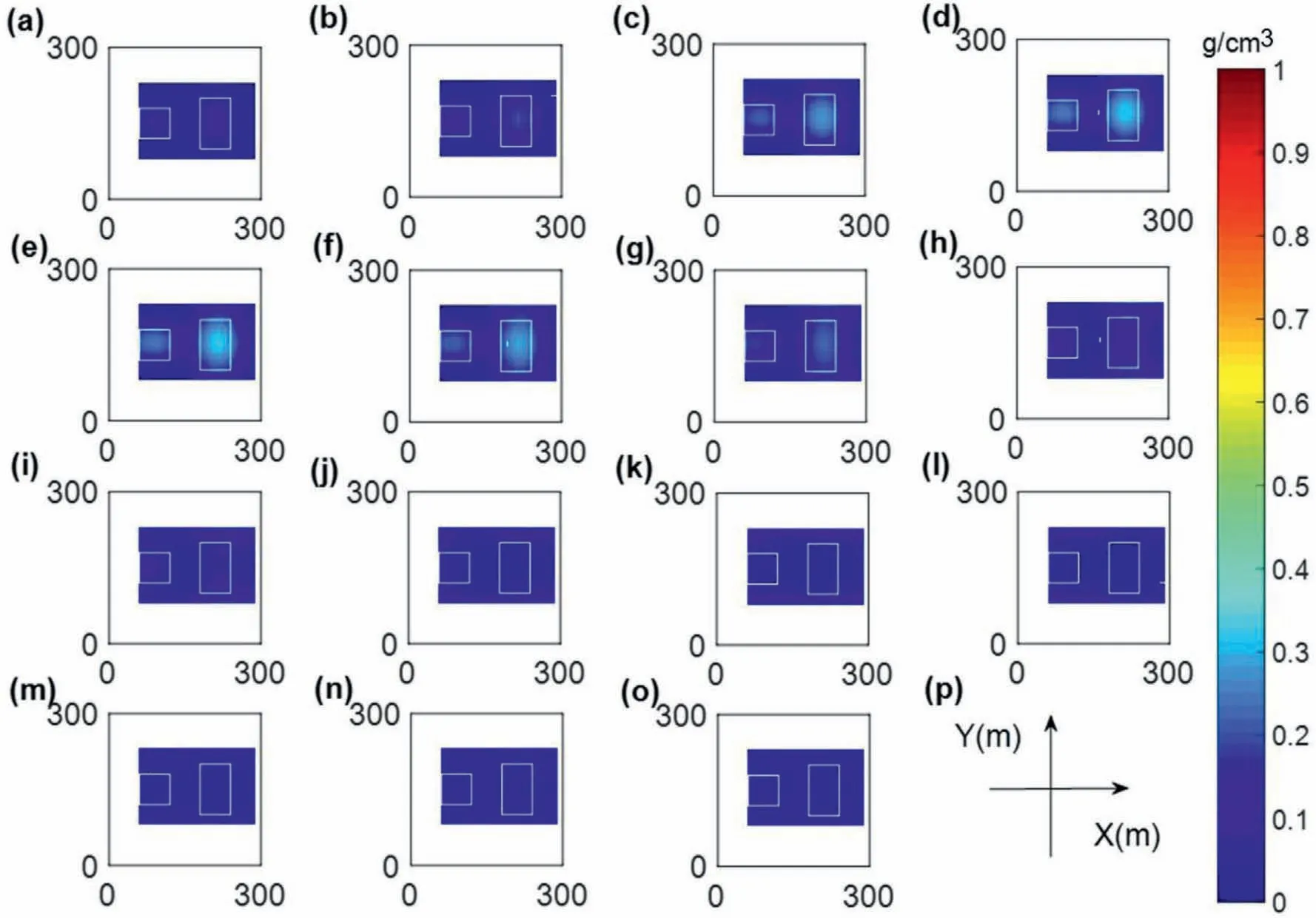
Fig.11. The results of performing the regularization inversion of model 2 with the parameter(0.1)based on the optimized meshing.The inversion results where z equals(a)5 m,(b)15 m,(c)25 m,(d)35 m,(e)45 m,(f)55 m,(g)65 m,(h)75 m,(i)85 m,(j)95 m,(k)105 m,(l)115 m,(m)125 m,(n)135 m and(o)145 m.(p)The Cartesian coordinates.(a)-(o)are consistent with the directions and length units shown in (p).
This model contains three geological bodies (see Table 1 for model details). A depiction of model 3 is shown in Fig. 14a. The gravity data computed for this model are shown in Fig. 14b. The random noise with the amplitude equal to 2%of the maximum data amplitude is added to the data set.Fig.14c and d show the results of the TAS and ASA, respectively. Model 3 also has the same original meshing as model 1. The corresponding details can be seen in Tables 1 and 2.
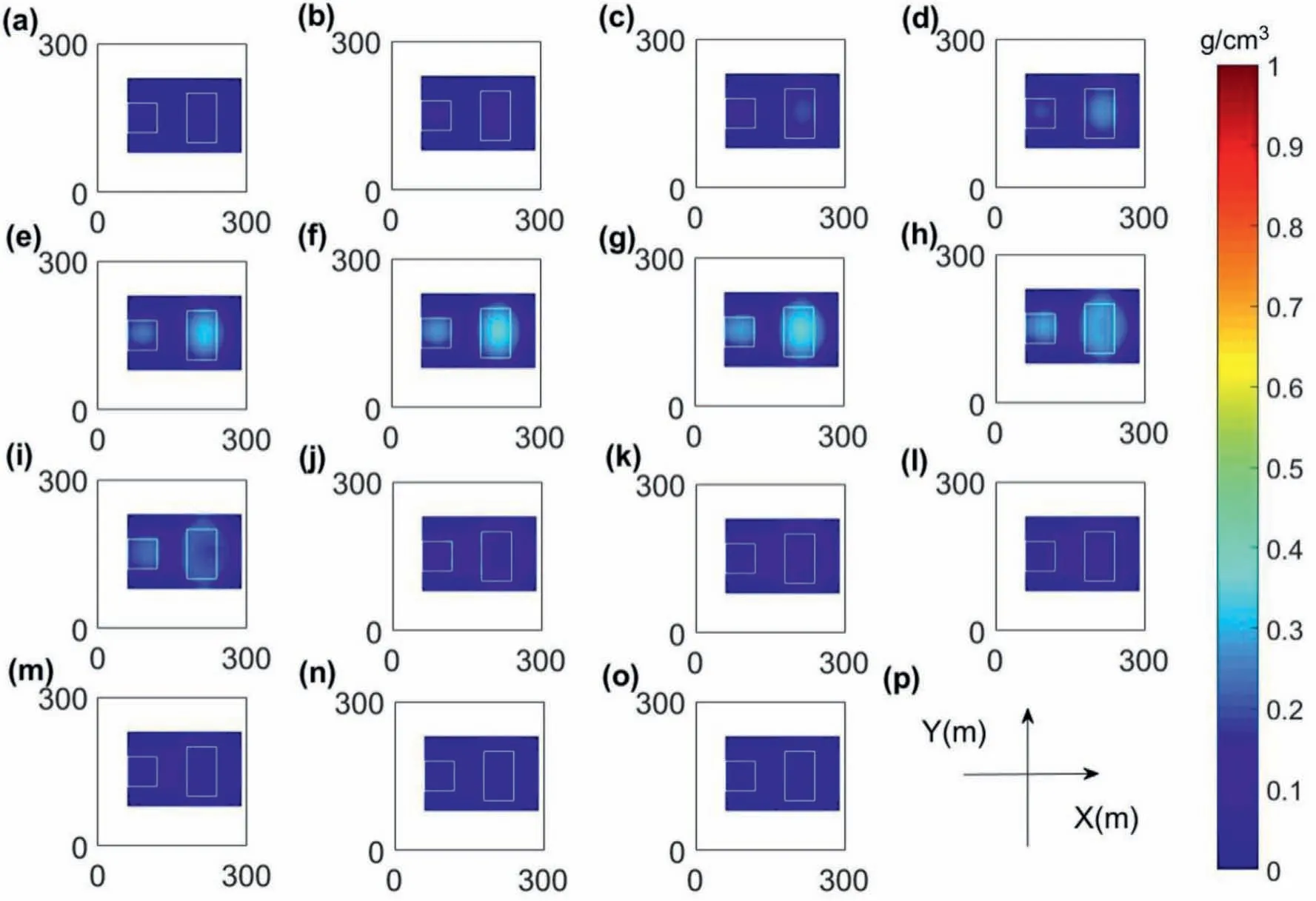
Fig.12. The display of the results from the regularization inversion with the parameters (0.1,0.3) based on optimized meshing and local weighting. The inversion results where z equals (a) 5 m, (b) 15 m, (c) 25 m, (d) 35 m, (e) 45 m, (f) 55 m, (g) 65 m, (h) 75 m, (i) 85 m, (j) 95 m, (k) 105 m, (l) 115 m, (m) 125 m, (n) 135 m and (o) 145 m. (p) The Cartesian coordinates. (a)-(o) are consistent with the directions and length units shown in (p).
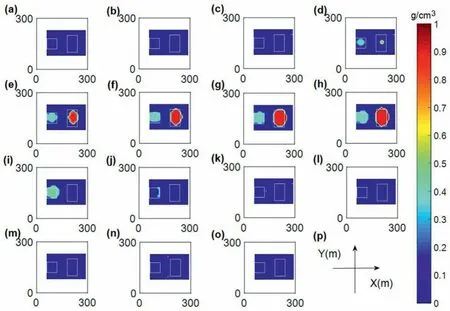
Fig.13. The results from the FCM inversion with the parameters(0.1,0.3)based on optimized meshing and local weighting.The inversion results where z equals(a)5 m,(b)15 m,(c)25 m,(d)35 m,(e)45 m,(f)55 m,(g)65 m,(h)75 m,(i)85 m,(j)95 m,(k)105 m,(l)115 m,(m)125 m,(n)135 m and(o)145 m.(p)The Cartesian coordinates.(a)-(o)are consistent with the directions and length units shown in (p).
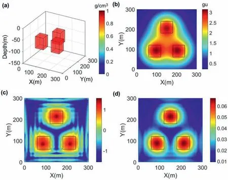
Fig.14. (a)Spatial location of synthetic model 3.(b)The contour map of forward gravity anomaly of synthetic model 3 adding Gaussian noise.The result of(c)the TAS and(d)ASA of the gravity data.
Using a similar method of model 1 for searching the pair of the optimized meshing and local weighted parameters, the values are set to 0.3 and 0.4, respectively. Fig. 15a shows the optimized meshing's result. Then, the curved region is also transformed into the regularized region (Fig. 15b). As can be seen in Table 2, the original 13500 grid cells are reduced to 6600. This result can also illustrate the correctness and effectiveness of the method of optimized meshing.
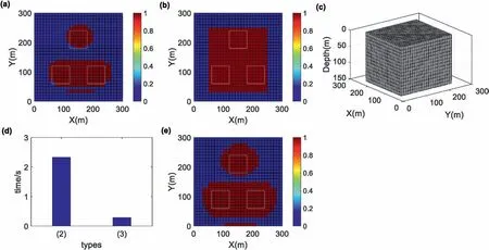
Fig.15. The meshing results of model 3 calculated using the results of the TAS with 0.3 as the optimized meshing parameter.The portion of the optimized meshing is changed from(a)the area of curved edges to(b)the area of regular shape.(c)An optimizing meshing map of the underground source body.(d)Forward time under different types.The type is the same as that of Fig. 5 (d). (e) The results calculated using the ASA with 0.4 as the local weighting parameter is displayed on a horizontal plane.
Fig. 15d shows the forward time in different situations, illustrating the efficiency of GPU acceleration. The corresponding forward time was 2.330 s and 0.290 s,respectively. The forward time based on the optimized meshing and the OpenAcc technology significantly decreased.Similarly,the other calculation times in the inversion also greatly reduced. The locally weighted region in red color obtained from the ASA results is shown in Fig. 15e. In this model, the maximum value is 300,and the minimum value is 20.
The smooth inversion result is shown in Fig. 16. Next, the regularized inversion is performed using the local weighting and optimized meshing (Fig.17). Comparing Figs.17 and 16, the latter inversion results are better: the more concentrated physical property values, the larger physical property difference, and the more approximate distribution of physical property to the distribution of the gravity anomaly.This result also shows the accuracy of the local weighting.
Then, the FCM inversion will be executed based on the latter smooth inversion.The condition of this example is similar to model 1.We set the number of this region to be 1,the cluster parameter C equals 2, the target cluster centers are 0 g/cc and 1.0 g/cc, and the whole region's parameters γlj(l=1,2...N,j=1,2...M) equal 1.Fig. 18 shows the results of the various layers of FCM inversion.Comparing Figs.16-18,the results obtained by FCM inversion using local and physical constraints are closer to the original model shown in Fig.14a, both in the spatial distribution and the magnitude of inverted physical property values.
These results also prove the advantages of the proposed method, both in efficiency and accuracy. Then, a more complex example holding multiple geological bodies with different depths and densities is used to illustrate the advantages of the proposed algorithm.
3.4. Fourth model
This model contains three geological bodies with the same shape, different densities, and different depths. The details of this model are described in Table 1,and a depiction of model 4 is shown in Fig. 19a. Fig. 19b depicts the gravity data of this model adding random noise with the amplitude equal to 2%of the maximum data amplitude. Fig. 19c and d show the results of TAS and ASA,respectively.
We again use the same strategy as in model 1 to find the parameters of optimized meshing and local weighting. Obviously,there are many discrete banded data points on the edge,and even the data values of these points are comparable to the data values in the main area of the data distribution(Fig.19c).Suppose the abovementioned optimization meshing strategy is directly used, some areas at the edges of the work area will be added to the mesh meshing area. Those parts are not the area where the geological bodies exist,which will cause less effect on the optimized meshing.So, it is impotent to use a suitable method for improving this disadvantage.In this paper, we zeroed the band data points of the TAS data in the outer component of the whole work area.Using the optimization meshing strategy will eliminate the regions where those discrete values exit, which will significantly improve the effect of optimal meshing.Then,the values of the optimized meshing and local weighted parameters are set to 0.2 and 0.33,respectively.Fig. 20a shows the distribution on the horizontal plane after the optimized meshing. The regularized meshing area is shown in Fig.20b.Fig.20c displays the 3D meshing cells.As shown in Table 2,the original grid cells 13500 are decreased to 6600.This result can also prove the correctness of the optimized meshing.

Fig.16. The results from the regularization inversion of model 3 with the parameter (0.3) based on optimized meshing.The inversion results where z equals(a) 5 m,(b)15 m,(c)25 m,(d)35 m,(e)45 m,(f)55 m,(g)65 m,(h)75 m,(i)85 m,(j)95 m,(k)105 m,(l)115 m,(m)125 m,(n)135 m and(o)145 m.(p)The Cartesian coordinates.(a)-(o)are consistent with the directions and length units shown in (p).

Fig.17. The results from the optimized regularization inversion of model 3 with the parameter pair(0.3,0.4)based on optimized meshing and local weighting.The inversion results where z equals (a) 5 m, (b) 15 m, (c) 25 m, (d) 35 m, (e) 45 m, (f) 55 m, (g) 65 m, (h) 75 m, (i) 85 m, (j) 95 m, (k) 105 m, (l) 115 m, (m) 125 m, (n) 135 m and (o) 145 m. (p) The Cartesian coordinates. (a)-(o) are consistent with the directions and length units shown in (p).
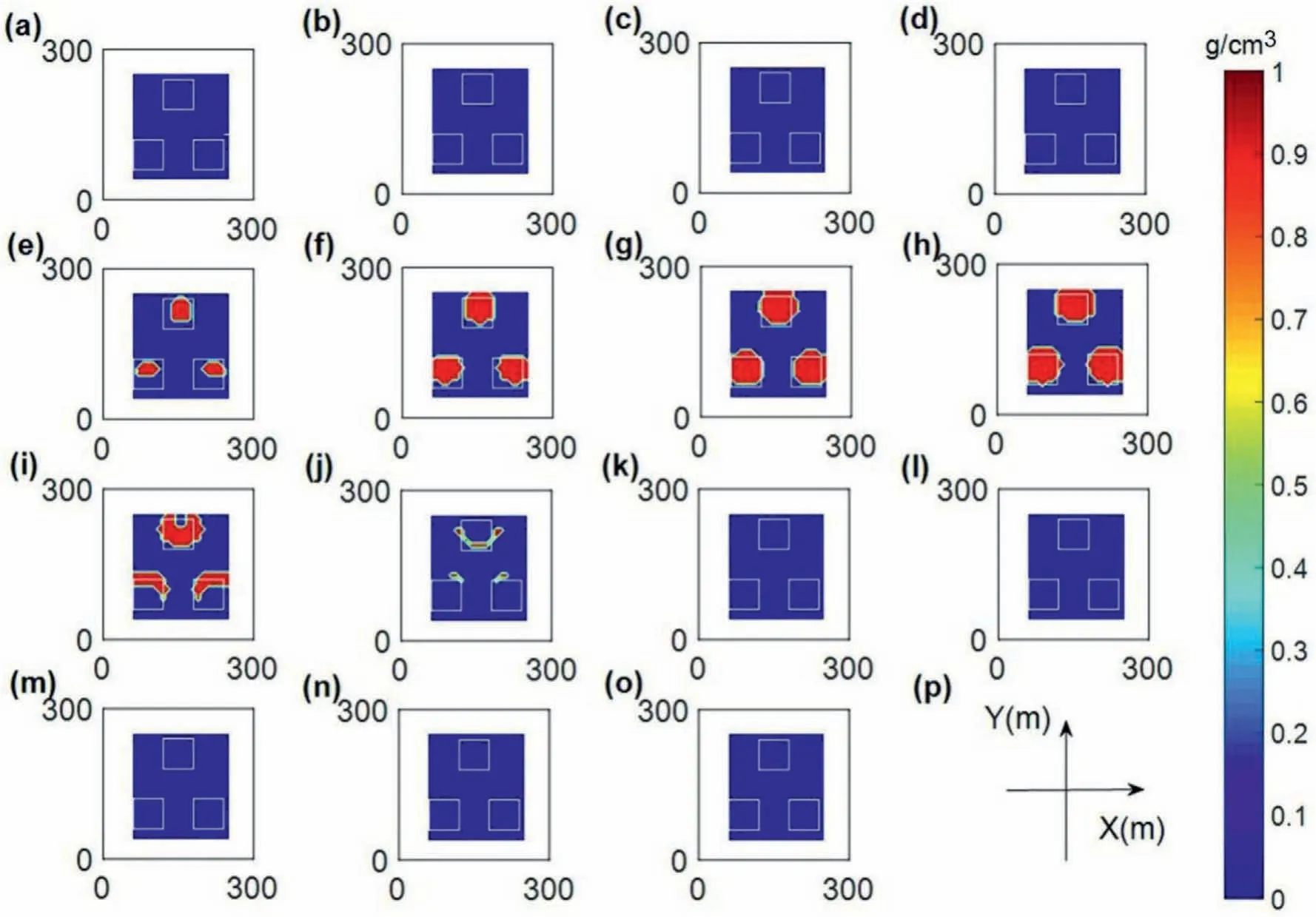
Fig.18. The results from the FCM inversion with the parameter pair(0.3,0.4).The inversion results where z equals(a)5 m,(b)15 m,(c)25 m,(d)35 m,(e)45 m,(f)55 m,(g)65 m,(h)75 m,(i)85 m,(j)95 m,(k)105 m,(l)115 m,(m)125 m,(n)135 m and(o)145 m.(p)The Cartesian coordinates.(a)-(o)are consistent with the directions and length units shown in (p).

Fig.19. (a)Spatial location of synthetic model 4.(b)The contour map of forward gravity anomaly of synthetic model 4 adding Gaussian noise.The result of(c)the TAS and(d)ASA of the gravity data.
Fig.20d presents the forward times with similar types as Fig.5d.The corresponding forward time is 2.321 s and 0.284 s,respectively.The latter forward time significantly decreases.Similarly,the other computation time in the inversion process is also reduced.The local weighting region is shown in Fig. 20e. In this part, the maximum and the minimum values used in local weighting are 700.0 and 20.0, respectively.

Fig.20. The meshing results calculated using the results of the TAS with 0.2 as the optimized meshing parameter.The portion of the optimized meshing is changed from(a)the area of curved edges to(b)the area of regular shape.(c)An optimizing meshing map of the underground source body.(d)Forward time under different types.The type is also the same as that of Fig. 5 (d). (e) The results calculated using the ASA with 0.33 as the local weighting parameter is displayed on a horizontal plane.
Then, the smooth inversion will be executed, and the corresponding inverted results are shown in Fig. 21. The results of regularized inversion based on optimized meshing and local weighting are displayed in Fig. 22. Comparing Figs. 21 and 22, the results of the latter inversion also have a better effect,the physical property distribution is more concentrated, the physical property difference is larger,and the distribution of physical property values is closer to the distribution of gravity anomaly.This also proves the accuracy and efficiency of the strategy of the local weighting.
The FCM inversion is executed based on the latter smooth inversion.From Fig.19a,the number of regions with different target cluster centers equals 3, and C equals 2 for each area. The first region's target cluster centers are 0 g/cc and 0.5 g/cc, the second region's target cluster centers are 0 g/cc and 1.0 g/cc, and the third region's target cluster centers are 0 g/cc and 1.5 g/cc. Then we set the weighting parameters γlj(l=1,2...N,j=1,2...M) of different regions from Fig. 19a. The results of FCM inversion are shown in Fig.20.From Figs.21-23,we find that the results obtained by FCM inversion are also closer to the original model(Fig.19a),both in the spatial distribution and the magnitude of inverted physical property values.
3.5. Fifth model
A more complicated synthetic model with positive and negative densities is used to demonstrate the accuracy of the algorithm proposed in this paper.Four geological bodies are contained in this model with different densities and depths. The details are also described in Table 1,and a depiction of model 5 is shown in Fig.24a.The gravity anomaly of model 5 adding random noise is shown in Fig. 24b. The results of TAS and ASA are shown in Fig. 24c and d,respectively.
The same strategy of model 1 is used to seek the parameters of optimized meshing and local weighting,and the responding values are 0.20 and 0.45,respectively.Similarly,because the TAS result has many discrete points with large values at the edge of the work area,the values of these discrete points are reset to zero for optimized meshing. The result of the optimized meshing is displayed in Fig.25a,and the responding regular result is shown in Fig.25b.The number of meshing cells is reduced to 6300. This result can also prove the correctness of the optimized meshing proposed in this paper.The region needed to execute local weighting by the result of ASA is presented in Fig. 25d, and the maximum and minimum values are 900.0 and 30.0, respectively.
The smooth inversion is carried out,and the responding result is displayed in Fig.26.Then,the similar inversion based on optimized meshing and local weighting is implemented,and the inverted result is shown in Fig.27.From Figs.26 and 27,the physical property of the latter inversion is larger, more concentrated, and closer to the distribution of gravity anomaly, which also proves the accuracy and efficiency of the local weighting. The FCM inversion is executed based on the result of the latter smooth inversion.From Fig.24a,the number of regions with different target cluster centers can be set to 4, and C equals 2.The first region's target cluster centers are 0 g/cc and 0.8 g/cc, the second region's target cluster centers are 0 g/cc and -0.5 g/cc, the third region's target cluster centers are 0 g/cc and -1.4 g/cc, and the fourth region's target cluster centers are 0 g/cc and 1.1 g/cc. Similarly, the weighting parameters γlj(l=1,2...N,j=1,2...M)can be obtained from Fig.24a.The results of FCM inversion are shown in Fig.28.From Figs.26-28,the results obtained by FCM inversion are also closer to the original model shown in Fig.24a,both in the spatial distribution and the magnitude of physical property values. These results once again certify the correctness of the proposed method,both in efficiency and accuracy.

Fig.21. The results from the regularization inversion of model 4 with the parameter(0.2) based on optimized meshing.The inversion results where z equals(a) 5 m,(b)15 m,(c)25 m,(d)35 m,(e)45 m,(f)55 m,(g)65 m,(h)75 m,(i)85 m,(j)95 m,(k)105 m,(l)115 m,(m)125 m,(n)135 m and(o)145 m.(p)The Cartesian coordinates.(a)-(o)are consistent with the directions and length units shown in (p).
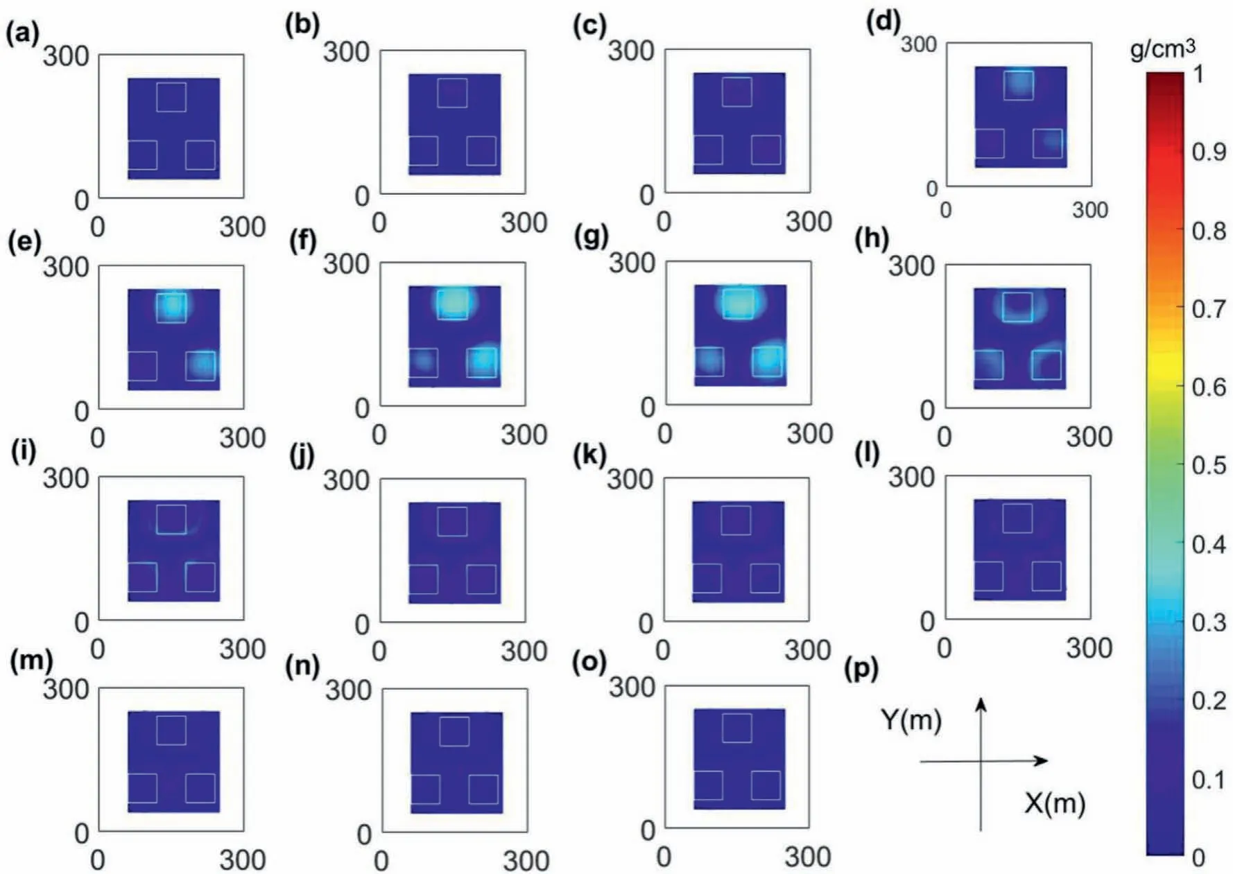
Fig.22. The results from the regularization inversion with the parameter pair(0.2,0.33)based on optimized meshing and local weighting.The inversion results where z equals(a)5 m,(b)15 m,(c)25 m,(d)35 m,(e)45 m,(f)55 m,(g)65 m,(h)75 m,(i)85 m,(j)95 m,(k)105 m,(l)115 m,(m)125 m,(n)135 m and(o)145 m.(p)The Cartesian coordinates.(a)-(o) are consistent with the directions and length units shown in (p).

Fig. 23. The results of performing the FCM inversion of model 4 with the parameter pair (0.2,0.33). The inversion results where z equals (a)5 m, (b) 15 m, (c) 25 m, (d) 35 m, (e)45 m,(f)55 m,(g)65 m,(h)75 m,(i)85 m,(j)95 m,(k)105 m,(l)115 m,(m)125 m,(n)135 m and(o)145 m.(p)The Cartesian coordinates.(a)-(o)are consistent with the directions and length units shown in (p).
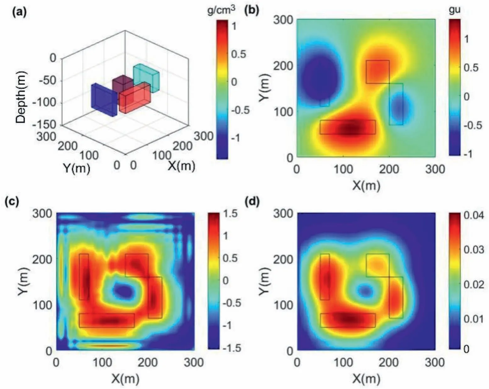
Fig.24. (a)Spatial location of synthetic model 5.(b)The contour map of forward gravity anomaly of synthetic model 5 adding Gaussian noise.The result of(c)the TAS and(d)ASA of the gravity data.
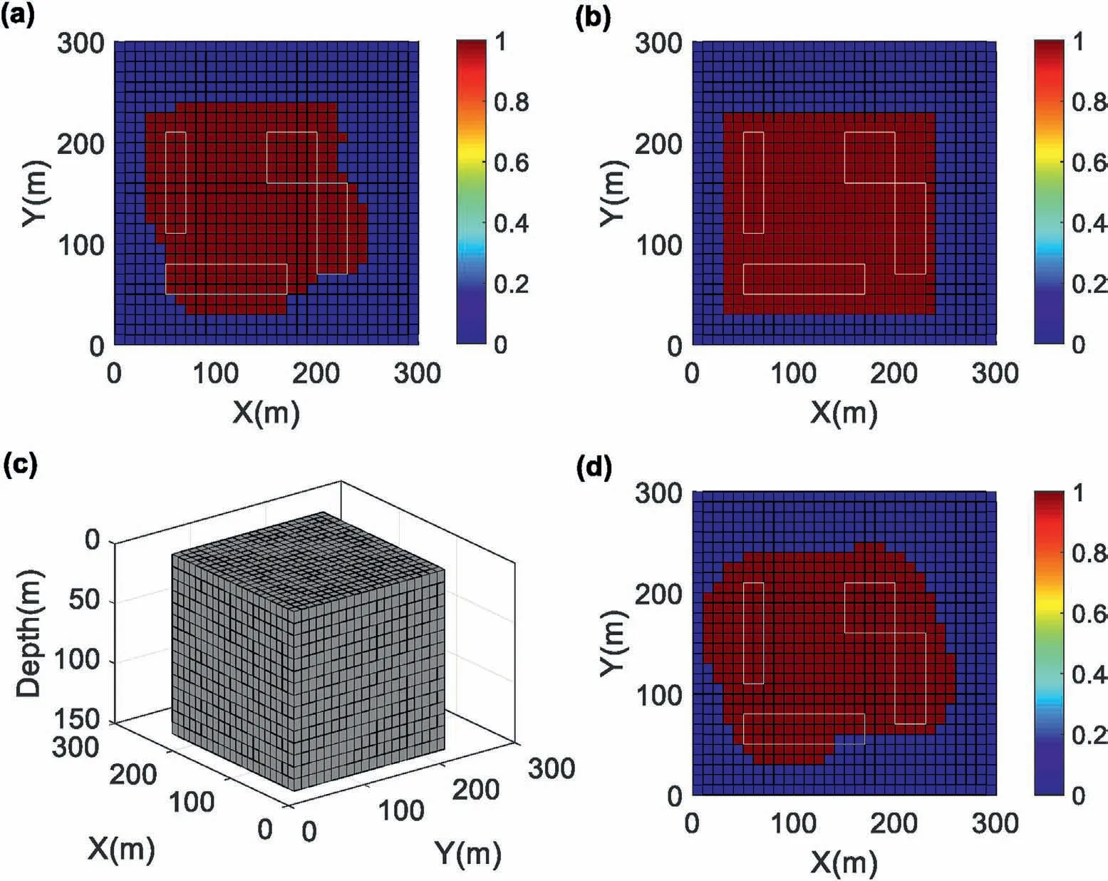
Fig. 25. The meshing results calculated using the TAS with 0.2 as the optimized meshing parameter. The portion of the optimized meshing is changed from (a) the area of curved edges to (b) the area of regular shape. (c) An optimizing meshing map of the underground source body. (d) The results calculated using the ASA with 0.45 as the local weighting parameter.
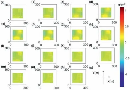
Fig.26. The results from the regularization inversion of model 5 with the parameter(0.2)based on optimized meshing. The inversion results where z equals(a)5 m,(b)15 m,(c)25 m,(d)35 m,(e)45 m,(f)55 m,(g)65 m,(h)75 m,(i)85 m,(j)95 m,(k)105 m,(l)115 m,(m)125 m,(n)135 m and(o)145 m.(p)The Cartesian coordinates.(a)-(o)are consistent with the directions and length units shown in (p).

Fig.27. The results from the regularization inversion with the parameters pair(0.2,0.45)based on optimized meshing and local weighting.The inversion results where z equals(a)5 m,(b)15 m,(c)25 m,(d)35 m,(e)45 m,(f)55 m,(g)65 m,(h)75 m,(i)85 m,(j)95 m,(k)105 m,(l)115 m,(m)125 m,(n)135 m and(o)145 m.(p)The Cartesian coordinates.(a)-(o) are consistent with the directions and length units shown in (p).
4. Conclusions
A new inversion scheme based on optimized processing from the edge detection is proposed in this paper. The method aims to reduce the meshing cells for accelerating computation,add several constraints to inversion for dropping the non-uniqueness of the inverted result, and use GPU acceleration technology to improve the efficiency of inversion.
Firstly, the edge detector method TAS is used to identify the edges of underground geological bodies with different depths,dividing the original meshing area into two parts. The first part is the area contained by the boundary of the underground anomalous bodies, and the second part is the region where the abnormal bodies do not exist.The first part obtained by TAS is a curved edge area even with discrete points.The selected irregular region of the first part is transformed into a regular region to facilitate the finite difference processing in the conventional smooth inversion theory.Thus, this simple processing greatly reduces the number of grid cells, which increases the inversion speed.
Secondly,the central detection method ASA is used to identify the centers of underground geological anomaly bodies, dividing the optimized meshing area into two parts. The first part is the area where the abnormal bodies are more likely to exist, and the second part is where the abnormal bodies are less likely to exist.When the priori model is 0 g/cc,the physical values of the second part are often 0 g/cc. Therefore, different values are used for the elements of the weighting matrix ws.This processing enables field data to constrain the spatial distribution of subsurface property values. Then, the guided FCM algorithm is used to combine the prior discrete physical property information for inversion. The combination of these two constraints in inversion can achieve a more reasonable spatial distribution,i.e.,a better correspondence between the distribution of physical property values and gravity anomalies on the horizontal plane.Moreover,the inversion results have a greater density difference with the priori physical information, which improves the accuracy of inversion results.
Thirdly,computational efficiency is a crucial aspect of inversion.The role of GPU acceleration technology is essential for gravity inversion. The OpenAcc technology, i.e., high-performance calculation on GPU,can be realized by adding simple direct languages to the original serial program. In this paper, the calculation of the forward matrix G,wmand the other large matrices in the iterative process becomes faster because of the OpenAcc technology.At the same time, the efficiency of the calculation is further improved by the optimized meshing.

Fig.28. The results of performing the FCM inversion of model 5 with the parameters pair(0.2,0.45).The inversion results where z equals(a)5 m,(b)15 m,(c)25 m,(d)35 m,(e)45 m,(f)55 m,(g)65 m,(h)75 m,(i)85 m,(j)95 m,(k)105 m,(l)115 m,(m)125 m,(n)135 m and(o)145 m.(p)The Cartesian coordinates.(a)-(o)are consistent with the directions and length units shown in (p).
The advantages of the proposed inversion method are demonstrated using synthetic data. Firstly, we use the results of TAS to optimize meshing,which significantly reduces the number of mesh cells and improves the efficiency of the inversion. Secondly, when 0 g/cc is used as the reference model,the results of the ASA are used to perform spatial constraints based on the optimized meshing.The inversion results are closer to the real model, both in the spatial distribution and the magnitude of the inverted physical property values. The priori physical constraint used in the guided FCM algorithm and the local spatial constraints of the ASA are integrated into the inversion process, and the results are closer to the real model both in terms of the spatial and numerical distribution,all of which demonstrate the advantages of the proposed inversion method. In terms of the efficiency, the optimized meshing greatly decreases the number of grid cells.It reduces the dimensions of the forward matrix G, wmand large matrices in the iterative process,which greatly improves the inversion efficiency. The efficiency of inversion is facilitated by implementing accelerated computation on GPU using OpenAcc technology.In other words,the new method proposed in this paper is more efficient and accurate for gravity inversion.
Conflicts of interest
The authors declare that there is no conflicts of interest.
Acknowledgments
This work was supported by the National Key Research and Development Program of China Project (Grant No.2018YFC0603502). We thank the reviewers for their valuable comments, which have helped us improve the quality of the manuscript.
Appendix A. Supplementary data
Supplementary data to this article can be found online at https://doi.org/10.1016/j.geog.2022.03.005.
杂志排行
Geodesy and Geodynamics的其它文章
- Three-dimensional coseismic deformation of the 2016 MW7.8 Kaikuora, New Zealand earthquake obtained by InSAR and offset measurements
- Dependence of epoch-wise two-way nested ANOVA estimates of variances of unmodeled effects present in relative GPS positioning on satellite elevation cutoff angle and PDOP mask
- Interseismic deformation rate of the Haiyuan fault system based on the modified SBAS method
- Delineation of sensitive coastal zone of northern Ramanathapuram coast, Tamilnadu, India, using a GIS approach
- Impact assessment of the seasonal hydrological loading on geodetic movement and seismicity in Nepal Himalaya using GRACE and GNSS measurements
- The Doppler effect induced by earthquakes: A case study of the Wenchuan MS8.0 earthquake
