Enhanced Photocatalytic CO2 Reduction over 2D/1D BiOBr0.5Cl0.5/WO3 SScheme Heterostructure
2022-08-11BichenZhuXiaoyangHongLiyongTangQinqinLiuHuaTang
Bichen Zhu , Xiaoyang Hong , Liyong Tang , Qinqin Liu , Hua Tang
1 School of Materials Science and Engineering, Jiangsu University, Zhenjiang 212013, Jiangsu Province, China.
2 School of Environmental Science and Engineering, Qingdao University, Qingdao 266071, Shandong Province, China.
Abstract: Catalytic reduction of CO2 to CO has been considered promising for converting the greenhouse gas into chemical intermediates.Compared to other catalytic methods, photocatalytic CO2 reduction,which uses solar energy as the energy input, has attracted significant attention because it is a clean and inexhaustible resource. Therefore,using high-performance photocatalysts for effective CO2 reduction under mild reaction conditions is an active research hotspot. However, several current photocatalysts suffer from low solar energy conversion efficiency due to the extensive charge recombination and few active sites, leading to low CO2 reduction efficiency. Generally, constructing an S-scheme heterojunction can not only promote charge separation but also help maintain strong redox ability. Therefore, the S-scheme heterojunction is expected to help in achieving high conversion activity and CO2 reduction efficiency. Here, 2D tetragonal BiOBr0.5Cl0.5 nanosheets and hexagonal WO3 nanorods were prepared using a simple hydrothermal synthesis method,and the 2D/1D BiOBr0.5Cl0.5 nanosheets/WO3 nanorods (BiOBr0.5Cl0.5/WO3) S-scheme heterojunction with near infrared(NIR) light (> 780 nm) response were prepared via the electrostatic self-assembly method for the photocatalytic CO2 reduction. Following characterization and analysis, including diffuse reflectance spectra (DRS), Mott-Schottky plots,transient photocurrent response, time-resolution photoluminescence spectrum (TRPL), electrochemical impedance spectroscopy (EIS), linear sweep voltammetry (LSV), and electron spin resonance (ESR) measurements, it can be demonstrated that an S-scheme carrier transfer route was formed between the 2D BiOBr0.5Cl0.5 nanosheets and 1D WO3 nanorods. Driven by the internal electric field, which was formed between the two semiconductors, electron migration was boosted, thus inhibiting the recombination of photogenerated carriers, while the stronger redox ability was maintained, thus providing good reduction efficiency over BiOBr0.5Cl0.5/WO3 composite in CO2 reduction. In addition, the 2D/1D nanosheet/nanorod structure allowed for enhanced interface contact with abundant active sites, which favored charge separation and increased photocatalytic activity. Furthermore, the amount of WO3 nanorods added during the preparation of the composites was altered, which led to the optimal amount of 5% (w, mass fraction) for the photocatalytic CO2 reduction. As a result, the BiOBr0.5Cl0.5/WO3 composite exhibited superior photocatalytic reduction performance with a CO yield of 16.68 μmol·g-1·h-1 in the presence of any precious metal cocatalyst or sacrificial agent, which was 1.7 and 9.8 times that of pure BiOBr0.5Cl0.5 and WO3, respectively. In addition, the BiOBr0.5Cl0.5/WO3 composite provided continuously increased CO yields with excellent selectivity under full-spectrum light irradiation, suggesting good photocatalytic stability.This work describes a novel idea for the construction of 2D/1D S-scheme heterojunction photocatalysts for efficient CO2 reduction.
Key Words: 2D/1D heterostructure; BiOBr0.5Cl0.5 nanosheets; WO3 nanorods; CO2 reduction; S-scheme
1 Introduction
With rapid economic development, large amounts of fossil fuels are consumed accompanied by the formation of large amounts of carbon dioxide, leading to a serious energy crisis and environmental pollution1-10. In order to solve these questions,researchers have explored green and low-energy technologies through extensive theoretical and experimental research11-23.Among them, the photocatalytic CO2reduction has received extensive attention because it can convert CO2into value-added chemical compound which is essential to alleviate the energy crisis and the greenhouse effect24-30. Recently, various semiconductor photocatalysts were developed for photocatalytic CO2reduction, such as TiO2, ZnO, WO3, CdS, g-C3N4and BiOBr31-36. Unfortunately, most single photocatalysts have limited redox potential, low charge separation efficiency and few active sites on the surface, resulting in poor CO2reduction37,38.Therefore, there is an urgent need to explore and design efficient photocatalytic systems.
In recent years, as a new type of photocatalyst, BiOBrxCl1-xsolid solution has attracted much attention because of its unique layered structure, adjustable band structures and high catalytic performance39-42. For example, Shenawi-Khalilet al. used a hydrothermal method to prepare BiOBr0.5Cl0.543. Whenx= 0.5,the BiOBr0.5Cl0.5showed the better degradation activity of rhodamine B and acetophenone compared with BiOCl and BiOBr44. Zhanget al. synthesized BiOBrCl and I-doped BiOBClrviaa solvothermal method45, and the BiOBClr and Idoped BiOBrCl illustrated greatly improved adsorption and photocatalytic activity compared with BiOX(X= Cl, Br, I)monomer. However, the charge separation efficiency of BiOBr1-xClxis still to be improved for its application in the field of photocatalysis46. To increase the photocatalytic performance,supporting precious metals, doping atoms and constructing heterojunctions have been developed and investigated47-52.Among the above strategies, the construction of heterojunctions by coupling semiconductors is considered as a feasible modification strategy. For instance, Liuet al. used a simple solvothermal method to prepare BiOBr with surface oxygen vacancies, and combined it with g-C3N4to construct a type-II heterojunction53. The formation of type-II heterojunction illustrated an improved separation efficiency of photogenerated carriers. Dehkordiet al. successfully constructed a type-II TiO2/g-C3N4heterojunction which showed high photocatalytic performance54. However, the traditional type-II heterojunction greatly reduces the redox ability of photogenerated carriers. In addition, the continuous transfer of photogenerated carriers in the conduction band or valence band of different components will be severely hindered due to the strong coulomb repulsion55.Recently, Yu’s group constructed a new S-scheme heterojunction composing of an oxidation photocatalyst (OP) and a reduction photocatalyst (RP) with a staggered belt structure has a unique electron transfer mode56,57. When OP and RP having different work functions are in close contact, directional electron migration would occur, leading to the construction of an internal electric field. Driven by the electric field force, photo-electrons of the OP would be consumed by the photo-holes of RP, leaving those with strong redox ability for photoreduction reactions58.Thus, the reasonable construction of S-scheme heterojunction is very promising to overcome the drawback of type-II heterojunction and enhance the photocatalytic performance.
To form an S-scheme heterojunction, coupling two suitable semiconductors is important. WO3has attracted broad interest in the field of photocatalysis due to its medium band gap (Eg= 2.4~2.8 eV), good oxidizing ability, and good stability under acidic and oxidizing conditions59. Previous reports also evidenced that the construction of the WO3-based composites was favor to improve the photocatalytic performance. For example, Jinet al.successfully prepared CdS-WO3composite which showed higher photocatalytic CO2reduction activity than single-phase photocatalyst60. What’s more, 2D/1D heterostructure have been extensively studied because it can accelerate the separation and transfer of photogenerated charges, offer large surface area for CO2adsorption, and exposes abundant active sites for surface catalysis. For example, Wanget al.demonstrate the rational design and construction of 2D/1D ZnIn2S4/In2O3heterostructures as photocatalysts for efficient CO2photoreduction61. However, to our knowledge, there are few reports on the construction of BiOBr0.5Cl0.5/WO32D/1D Sscheme heterojunction for photocatalytic CO2reduction.Besides that, the relationship between their physicochemical properties and photocatalytic performance is worth investigating.
Herein, we successfully prepared BiOBr0.5Cl0.5/WO3composite through a hydrothermal way followed up an electrostatic self-assembly method. The optimized BiOBr0.5Cl0.5/WO3S-scheme heterojunction exhibited high photocatalytic CO2reduction performance, and the CO yield was up to 16.68 μmol∙g-1∙h-1, which was notably better than that of BiOBr0.5Cl0.5and WO3. Meanwhile, photoelectrochemical characterization and transient fluorescence results illustrated that the reasonable design of the S-scheme heterojunction can not only effectively inhibit the recombination of strongly redoxcapable photogenerated carriers, but also provide the strong photoredox ability for CO2reduction. In addition, the 2D/1D nanosheets/nanorods structure enhanced the interface contact and provided abundant reaction sites. The in-depth discussion on S-scheme mechanism enriches the studies of heterostructures on BiOBr0.5Cl0.5-based photocatalysts with higher photocatalytic CO2reduction activity and stability.
2 Materials and methods
2.1 Materials
All the reagents including Na2WO4·2H2O (> 99.5%), NaCl (>99.5%), HCl (36.0%-38.0%,w, mass fraction), Bi(NO3)3·5H2O(> 99.5%), HNO3(65.0%-68.0%,w), NH4Br (> 99.0%) and NH4Cl (> 99.5%) are all obtained from commercial sources(Sinopharm) and used directly without further purification.
2.2 Preparation of WO3 Nanorods
WO3nanorods was synthesized by a simple solvothermal process62. First, 1.056 g of Na2WO4·2H2O and 0.935 g of NaCl were dissolved in 30 mL H2O and stirred continuously for 30 min. Then, HCl (3 mol·L-1) solution was added to adjust the pH of the above solution to 2 under continuous stirring for 3 h. The solution was then dumped into a 50 mL Teflon lined autoclave and heated to 180 °C and maintain 24 h to form the WO3nanorods. Finally, the prepared photocatalyst was centrifuged for several times until the pH value of WO3solution reach to 7 after cooling to room temperature, and dried at 60 °C for 12 h for further testing. In addition, the 2D WO3nanosheets and 0D WO3nanoparticles were prepared for comparation and the detailed description can be seen in the Supporting information.
2.3 Preparation of BioBr0.5Cl0.5 nanosheets
Typically, BiOBr0.5Cl0.5photocatalyst was prepared by a precipitation route63. Typically, 0.02 mol of Bi(NO3)3·5H2O and HNO3solution (2 mL) were scattered in 20 mL H2O and stirred vigorously to obtain a transparent solution. Additionally, 0.02 mol of ammonium halide (molar ratio of NH4Br/NH4Cl = 1 : 1)was mixed with 20 mL H2O, and the solution was quickly added.After stirring for 2 h to form BiOBr0.5Cl0.5nanosheets,centrifuged the product with H2O until the pH value of BiOBr0.5Cl0.5solution reach to 7and dried 60 °C for 12 h to collect the white precipitate. Finally, BiOBr0.5Cl0.5nanosheets with high crystallinity were obtained by calcination at 300 °C for 1 h under air atmosphere. For comparison, pure BiOBr and pure BiOCl were also prepared using the same method except that the amount of NH4Br and NH4Cl were increased to 0.02 mol,respectively.
2.4 Preparation of BiOBr0.5Cl0.5/WO3 2D/1D composites
Firstly, 0.2 g of BiOBr0.5Cl0.5nanosheets were spread to 50 mL of H2O and treated by ultrasound for 0.5 h to obtain a white suspension. Then, 0.05 g WO3nanorods were poured into 50 mL deionized water and treated by ultrasound for 0.5 h to obtain uniform WO3nanorods solution. Different volumes including 2,6, 10 and 14 mL of WO3solution were added and stirred at constant rate for 12 h, respectively. Finally, the BiOBr0.5Cl0.5/WO3nanocomposites with different WO3contents were obtained by centrifuged and washed with water and heated(60 °C, 12 h). The obtained samples were named as BiW-X(X=1, 2, 3 and 4, represented the WO3mass ratio of 1%, 3%, 5% and 7%), respectively (Scheme 1). The Zeta potential of BiOBr0.5Cl0.5is 13.8 mV while the Zeta potential of WO3is-39.8 mV which favored the formation of the interfaces between the BiOBr0.5Cl0.5nanosheets and WO3nanorodsviathe electrostatic self-assembly method (Fig. S1).
2.5 Characterization
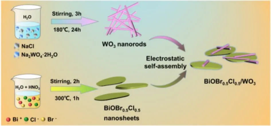
Scheme 1 Schematic illustration of the preparation for BiOBr0.5Cl0.5/WO3 composites.
The crystal structures, morphology and composition were testedviapowder X-ray diffraction diffractometer (XRD,Rigaku D/Max-2550, Japan), scanning electron microscopy(SEM, JEOL JXA-840A, Japan), high-resolution transmission electron microscopy (HRTEM, JEOL JEM-100CX II, Japan), a zeta sizer (Malvern Panalytical ZS90, UK), and X-ray photoelectron spectroscopy (XPS, Perkin Elmer PHI ESCA-5000C, USA). Light absorption and photoluminescence were observed by UV-Vis diffuse reflectance spectra ((DRS,Shimadzu UV2600, Japan), BaSO4as a reference) and timeresolved photoluminescence attenuation spectra (TRPL,Edinburgh FI/FSTCSPC920, UK). The electrochemical properties were measured by a electrochemical workstation(Chenhua Instrument CHI760E, China) using a 420 nm LED lamp as the light source and 0.5 mol·L-1sodium sulfate as the electrolyte solution. The standard three-electrode system including platinum electrode (counter electrode), Ag/AgCl electrode (reference electrode) and working electrode (80 μL prepared samples were uniformly dispersed on 2 × 2 cm FTO glass, and then kept in an oven at 70 °C for 2 h). The flat band potential (Efb)vs.Ag/AgCl of samples wereviathe Mott-Schottky plot, andEfbvs.NHE was obtained using equation ofEfb=EAg/AgCl+ 0.059 pH +E0Ag/AgCl(E0Ag/AgCl= 0.197 eV, pH =6.8). Electron spin resonance (ESR, Bruker A300, Germany)spectra were performed on an electron paramagnetic resonance spectrometer.
2.6 Photocatalytic CO2 reduction test
The photocatalytic performance was tested in the all-glass automatic online trace gas analysis system (Labsolar-6A,Beijing Perfectlight Technology Co., Ltd.). In general, 25 mg of photocatalyst was dissolved in 50 mL of H2O and then the above solution was added to a 200 mL quartz reactor. Before turning on the lights, the reaction vessel was pumped into a vacuum and filled with CO2gas (99.999%) with a system pressure of 60 kPa.Finally, high purity CO2gas was introduced to the system and the pressure was stabilized at 80 kPa and keep the temperature at 5 °C. The light source was provided by a Xenon lamp (PLSSXE300D, Beijing Perfectlight Technology Co., Ltd.). At intervals of 1 h, automatic injection analysis was performed by using a gas chromatograph (Shimadzu GC-2014).
3 Results and discussion
The XRD patterns of BiOCl, BiOBr0.5Cl0.5and BiOBr illustrate that the diffraction peaks located at 2θ= 11.96°, 24.04°,25.82°, 32.33°, 33.54°, 40.88°, 46.58° and 58.66° are corresponding to the (001), (002), (101), (102), (110), (112),(200) and (212) crystal planes of BiOCl, respectively (Fig. 1a).The XRD patterns of the prepared BiOBr and BiOCl are in accordance with tetragonal BiOBr (JCPDS No. 09-0393) and tetragonal BiOCl (JCPDS No. 06-0249)64, respectively. The BiOBr0.5Cl0.5illustrates similar XRD patterns with that of BiOBr, indicating solid solution form of BiOBr0.5Cl0.5. Fig. 1b presents the XRD patterns of the prepared BiOBr0.5Cl0.5, WO3and the composites with different proportions. Pure monoclinic WO3corresponds to standard XRD card (JCPDS No. 33-1387)64.All characteristic peaks of BiOBr0.5Cl0.5/WO3matches well with that of BiOBr0.5Cl0.5without significant shifts. It clearly observed that the characteristic diffraction peaks of WO3are not observed in BiW-1 and BiW-2, which may be due to the amounts of WO3are too little. However, when the content of WO3increases, the signals of the WO3show up in BiW-3 and BiW-4,in which the diffraction peaks at 28.17° and 36.57° are assigned to the (200) and (201) crystal planes of monoclinic WO3.
The morphology and microstructure of BiW-3, WO3and BiOBr0.5Cl0.5were studied by SEM, TEM and HRTEM. In addition, more detailed structural information of WO3and BiOBr0.5Cl0.5was further revealed by the HRTEM test.BiOBr0.5Cl0.5exhibits the irregular nanosheet structure with a diameter in the range of 0.6 to 1 μm and a thickness of 40 nm(Fig. 2a,b). From Fig. 2c, lattice edges with planar lattice spacing of 0.345 and 0.271 nm are observed, attributing to the BiOCl(101) and BiOBr (102) in the BiOBr0.5Cl0.5composite. The obtained WO3sample has a distinct one-dimensional (1D)nanorod structure (Fig. 2d,e). For WO3, a lattice spacing value of 0.391 nm is calculated which matches the (001) lattice plane of WO3nanorods (Fig. 2f). This further confirms that the BiOBr0.5Cl0.5sample is a solid solution rather than simple mixture of BiOCl and BiOBr. The SEM and TEM pictures of BiW-3 manifest that the nanorods distribute on the surface of BiOBr0.5Cl0.5nanosheets forming a 2D/1D heterojunction (Fig.2g,h). The elemental mapping of the BiW-3 confirms the presence of all elements including Br, Cl, O, Bi and W in the ternary nanocomposite, supposing the successful synthesis of the BiOBr0.5Cl0.5/WO3composite (Fig. 2i).

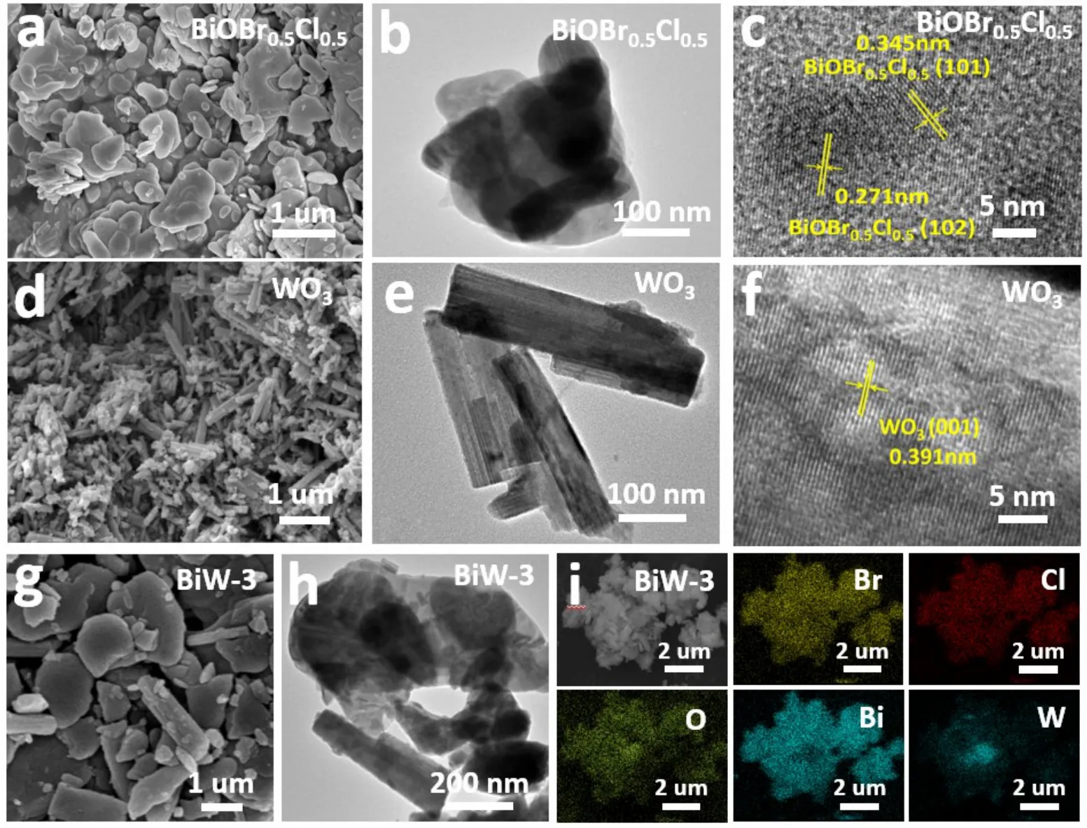
Fig. 2 SEM, TEM and HRTEM images of BiOBr0.5Cl0.5 (a, b, c) and WO3 (d, e, f). SEM, TEM images (g, h) and element mapping (i) of BiW-3 composite.
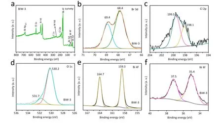
Fig. 3 The XPS survey spectrum of BiW-3 composite (a) and the high-resolution spectra of Br 3d (b), Cl 2p (c), O 1s (d), Bi 4f (e) and W 4f (f).
The chemical compositions and elemental states of the BiW-3 composites were investigated by XPS, and the results are shown in Fig. 3. In the survey spectrum of BiW-3, the signals of Br, Cl, O, Bi, and W elements are observed, revealing that BiOBr0.5Cl0.5/WO3composite has been successfully prepared(Fig. 3a)65,66. In the Br 3dXPS spectrum, there are two significant peaks located in 68.4 and 69.4 eV assigning to the signals of Br 3d5/2and Br 3d5/2, respectively (Fig. 3b). In the Cl 2pXPS spectrum, there are two peaks located at 198.1 and 199.5 eV assigning to the signals for Cl 2p3/2and Cl 2p1/2,respectively (Fig. 3c). For the O 1sXPS spectra, the peak located at about 530.2 and 531.7 eV can also be observed (Fig. 3d). The peaks located at about 159.3 and 164.7 eV in the XPS spectrum of Bi 4fare attribute to the signal of Bi3+4f7/2and Bi3+4f5/2(Fig.3e). The peaks at 35.4 and 37.5 eV origin from the W 4fsignals(Fig. 3f). These results further reveal the composition of BiOBr0.5Cl0.5and WO3.
As presented in Fig. 4a,b, the CO yield of BiOBr0.5Cl0.5(9.91 μmol∙g-1∙h-1) is higher than that of BiOBr (3.58 μmol∙g-1∙h-1)and BiOCl (8.08 μmol∙g-1∙h-1), indicating that the BiOBr0.5Cl0.5possesses better reduction performance than that of pure BiOBr and BiOCl. Meanwhile, all the BiW composite samples present higher reduction efficiency compared with that of pure BiOBr0.5Cl0.5and WO3(Fig. 4c,d). When the content of WO3increases, the photocatalytic activity in the CO2reduction reaction increases and the BiW-3 sample shows the highest CO2reduction rate of 16.68 μmol∙g-1∙h-1. However, when 7% WO3is added, the BiW-4 illustrates a decreased CO2reduction rate for 9%, because excessive WO3may lead to the formation of electron-hole recombination centers. As expected, the BiOBr0.5Cl0.5-WO3-3 composite also exhibits better CO2reduction efficiency offering a CO yield of 16.68 μmol∙g-1∙h-1than that of BiOCl-WO3-3 (12.68 μmol∙g-1∙h-1) and BiOBr-WO3-3 (5.71 μmol∙g-1∙h-1) composites (Fig. S2). The above results indicate that mixed halides of BiOBr0.5Cl0.5-WO3-3 shows improved photocatalytic CO2reduction performance.
In addition, the stability of BiW-3 photocatalysts in the CO2reduction reaction was tested, and the results were shown in Fig.4e and S3. As can be seen in the recycling reactions, the CO2reduction performance of the composite showed a slightly decrease after 4 cycles due to the inevitable sample loss in the recovery process (Fig. S3). Upon full-spectrum light irradiation,the CO yield continuously enhanced with the prolonged reaction time (the total irradiation time is 16 h) suggesting the good stability. Besides, the XRD patterns of BiW-3 photocatalysts before and after CO2reduction reaction presented no evident variation of crystalline structure, which was in consist with the long-time reaction and indicated the excellent reusability and stability of the BiW-3 sample (Fig. 4f).
To further investigate the mechanism of strengthened photocatalytic CO2reduction activity of BiW-3, transient photocurrent response, electrochemical impedance spectroscopy(EIS), linear sweep voltammetry (LSV) and time-resolved transient photoluminescence (TRPL) measurements were tested.Fig. 5a displays the photocurrent responses of BiOBr0.5Cl0.5,WO3and BiW-3 under 420 nm LED irradiation. Compared with BiOBr0.5Cl0.5and WO3, the photocurrent density of BiW-3 is the highest, manifesting the highest separation efficiency of carriers for BiW-3. The EIS Nyquist plots of BiOBr0.5Cl0.5, WO3and BiW-3 are displayed in Fig. 5b. The Nyquist diagram of BiW-3 has the smallest semicircle, demonstrating that the faster transfer photogenerated carriers in BiW-3. As depicted in Fig. 5c, the overpotential of BiOBr0.5Cl0.5is greatly enhanced after coupling with WO3, and BiW-3 offers a highest value of overpotential which is in accord with the experimental trend in the photocatalytic CO2reduction reaction. Fig. 5d presents the TRPL results of BiOBr0.5Cl0.5and BiW-3 samples. In comparison to pristine BiOBr0.5Cl0.5, BiW-3 illustrates a decreased average PL lifetime (τ, 0.491 ns)67. The shorter lifetime of BiW-3 signals the existence of efficient nonradiative decay pathways in the composites which further implying the main transfer pathway for electrons from BiOBr0.5Cl0.5to WO3.
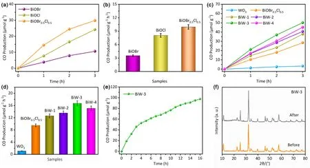
Fig. 4 The CO yield (a) and hourly CO production rates (b) of BiOCl, BiOBr and BiOBr0.5Cl0.5, the photoreduction activity (c) and hourly production rates (d) of CO over as-prepared samples, the CO yield of BiW-3 within 16 h (e), and XRD patterns of BiW-3 before and after the reaction (f).
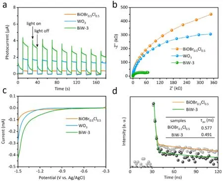
Fig. 5 The transient photocurrent response (a), EIS (b), LSV curves of BiOBr0.5Cl0.5, WO3 and BiW-3 (c),TRPL spectra of BiOBr0.5Cl0.5 and BiW-3 samples (d).
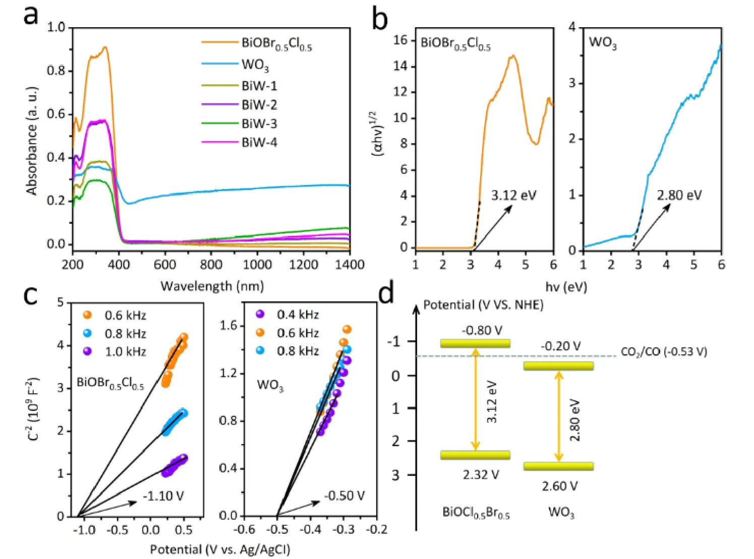
Fig. 6 UV-Vis diffuse reflection image of prepared samples (a), the band gap of BiOBr0.5Cl0.5 and WO3 (b), Mott-Schottky plots (c) and the schematic diagram of the band structure (d) of BiOBr0.5Cl0.5 and WO3.
UV-Vis diffuse reflectance spectra (DRS) were tested to investigate the optical properties of as-prepared samples, and the results were shown in Fig. 6a. For pure samples, the absorption edge of BiOBr0.5Cl0.5nanosheets was located at 410 nm. For the WO3nanorods, the absorption edge was located at 442 nm and showed a NIR light (780-1400 nm) absorption which was caused by the LSPR effect of WO3nanorods68. Furthermore, the absorption of BiOBr0.5Cl0.5/WO3showed a broadened light response in the NIR light region (780-1400 nm), which suggested that coupling with WO3could enhance the light absorption ability. According to the formula of Tauc equation,theEgof BiOBr0.5Cl0.5and WO3was estimated to be 3.12 and 2.80 eV, respectively (Fig. 6b). The Mott-Schottky plots of BiOBr0.5Cl0.5and WO3samples were shown in Fig. 6c. It can be clearly seen that the two linear plots possessed positive slopes,which illustrated both photocatalysts are n-type semiconductors.According to the intercept of the plots on theX-axis, it can be observed that theEfbof BiOBr0.5Cl0.5and WO3are -1.10 and-0.50 V (vs. Ag/AgCl, pH = 6.8), corresponding to -0.50 and 0.10 V (vs.NHE), respectively. It is known that theECBis more negative (0.3 V) thanEfbfor n-type semiconductor, as a result,theECBof BiOBr0.5Cl0.5and WO3are -0.80 and -0.20 V (vs.NHE) while theEVBare 2.32 and 2.60 V (vs.NHE), respectively.The band structures of the two semiconductors are displayed in Fig. 6d which could form the type II or S-scheme.
To further confirm the mechanism of enhanced photocatalytic CO2reduction on BiOBr0.5Cl0.5/WO3photocatalysis system, the ESR was performed with DMPO as radical scavenger.Generally, the redox potentials of O2/·O2-and OH-/·OH are -0.33 and 1.99 eV (vs.NHE)69, respectively. The semiconductors which have a negative potential or positive potential than that of-0.33 and 1.99 eV (vs. NHE) could generate ·O2-and ·OH,respectively. As can be seen in Fig. 7a, the quartet peaks with an intensity ratio of 1 : 1 : 1 : 1 are ascribed to the signal of DMPO-·O2-. Under light irradiation, only BiW-3 and BiOBr0.5Cl0.5could afford the ·O2-while WO3could not generate the ·O2-, which is due to fact that the CB of WO3is not negative enough to reduce O2into ·O2-. In addition, no signal can be observed under dark condition, suggesting the photogenerated electrons accumulate on the CB of WO3in the BiW-3 composite. This result further confirms that type II heterojunction between the BiOBr0.5Cl0.5and WO3can be ruled out, and an S-scheme charge transfer route is involved. According to previous reports, the work functions of BiOBr and BiOCl are 5.86 and 5.78 eV, respectively, which are lower than that of WO3(6.23 eV), indicating the electron transfer from BiOBr0.5Cl0.5to WO3thus constructing of internal electric fields from BiOBr0.5Cl0.5to WO366,70,71. Based on the fact that all the VB positions of BiOBr0.5Cl0.5and WO3are all positive enough to generate ·OH, all these samples could generate ·OH under light irradiation from Fig. 7b. All these ESR evidences confirm the S-scheme charge transfer route. Furthermore, the signal intensities of DMPO-·O2-and DMPO-OH increase with the prolonged irradiation time, indicating the efficiency photogenerated electron-hole separation for the BW-3 composite(Fig. 7c,d).
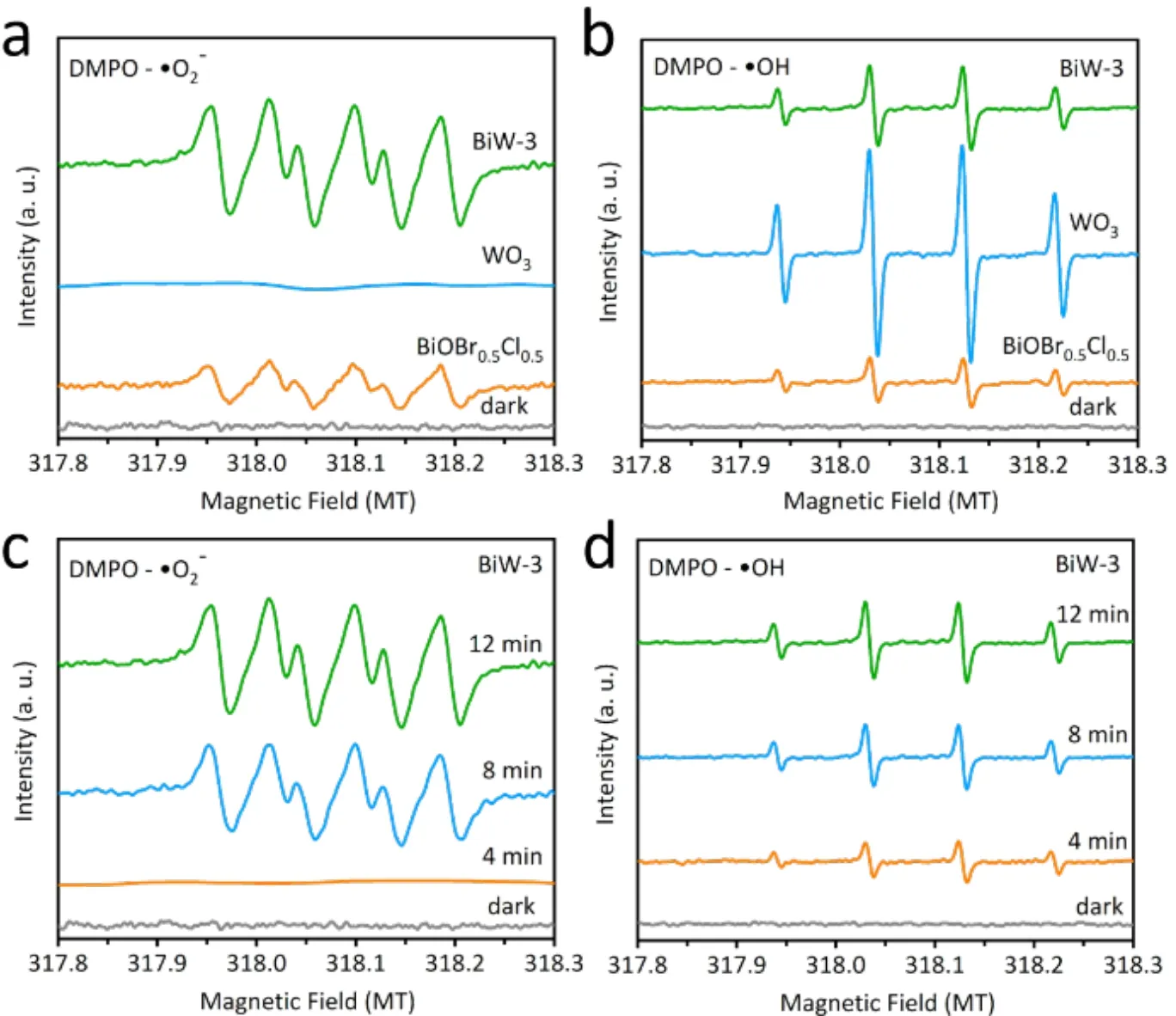
Fig. 7 ESR spectra of BiOBr0.5Cl0.5, WO3 and BiW-3 photocatalysts in CH3OH (a) and H2O (b) solvent with DMPO as radical trapper. ESR spectra of radical adducts trapped by DMPO (·O-2 and ·OH) over BiW-3 (c, d).
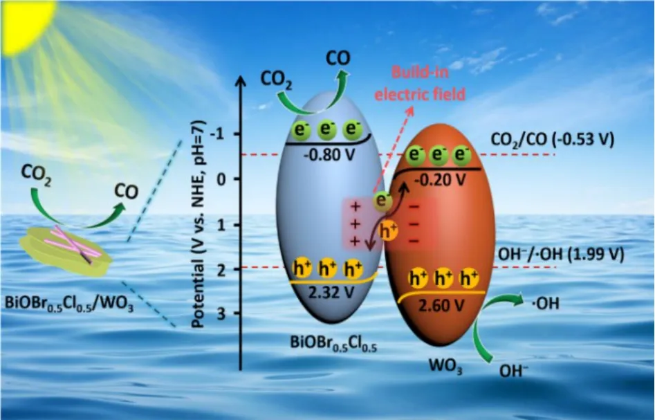
Fig. 8 The possible S-scheme mechanism of BiOBr0.5Cl0.5/WO3 composite.
According to the above analysis, a possible S-scheme mechanism of the CO2reduction reaction is proposed. As shown in Fig. 8, BiOBr0.5Cl0.5and WO3serve as the reductive and oxidative semiconductors withEgvalues of 1.52 and 2.40 eV,respectively. TheECBof BiOBr0.5Cl0.5is -0.80 Vvs.NHE (pH =7), which is negative than that of WO3, while theEVBof BiOBr0.5Cl0.5is 2.32 Vvs.NHE (pH = 7). After contact with each other, the electrons migrate from BiOBr0.5Cl0.5to WO3forming an internal electric field (IEF). When irradiated by visible light,e--h+pairs are photogenerated in BiOBr0.5Cl0.5and WO3. Driven by the IEF, the photogenerated electrons in CB of WO3react with the holes in the VB of BiOBr0.5Cl0.5, leaving the e-on the CB of BiOBr0.5Cl0.5and h+on the VB of WO3, respectively. This kind of photogenerated carries transfer route offers the composite with strongest redox ability and improves the charge transfer efficiency. Then, the e-on the CB of BiOBr0.5Cl0.5tends to reduce CO2into CO while the h+stored in WO3VB is trapped in OH-to produce ·OH. The results show that the S-scheme heterojunction not only improves the separation efficiency of e--h+pairs, but also enhances the redox potential of the composite photocatalyst.
4 Conclusions
In summary, BiOBr0.5Cl0.5/WO3heterojunction with the 2D/1D nanosheets/nanorods structure was successfully fabricated for efficient photocatalytic CO2reduction. The Sscheme charge transfer in BiOBr0.5Cl0.5/WO3heterojunction was proved using ESR measurements. The photocatalytic activity of S-scheme BiOBr0.5Cl0.5/WO3heterojunction catalyst was significantly improved, and the CO2photoreduction conversion rate was up to 16.68 μmol∙g-1∙h-1which was 1.7 and 9.8 times higher than that of pristine BiOBr0.5Cl0.5and WO3, respectively.The reasonable development of BiOBr0.5Cl0.5/WO3heterojunction not only promoted the separation of useful e--h+pairs, but also offered high reduction ability for multi-electron CO2reduction reaction. In addition, introduction of WO3greatly increased the light response range, providing more photogenerated carriers. Therefore, this work proposes a promising approach to design S-scheme heterojunction toward high-efficiency gas-liquid photocatalytic CO2reduction reaction without any cocatalysts and sacrificial agents.
Supporting Information:available free of chargeviathe internet at http://www.whxb.pku.edu.cn.
杂志排行
物理化学学报的其它文章
- Insights into Mechanism of CsPbBr3 Nanocrystal Interfacial Modifier in Perovskite Solar Cells
- Hollow NiCo2S4 Nanospheres as a Cocatalyst to Support ZnIn2S4 Nanosheets for Visible-Light-Driven Hydrogen Production
- A 0D/2D Bi4V2O11/g-C3N4 S-Scheme Heterojunction with Rapid Interfacial Charges Migration for Photocatalytic Antibiotic Degradation
- Rationally Designed Mn0.2Cd0.8S@CoAl LDH S-Scheme Heterojunction for Efficient Photocatalytic Hydrogen Production
- P-Doped g-C3N4 Nanosheets with Highly Dispersed Co0.2Ni1.6Fe0.2P Cocatalyst for Efficient Photocatalytic Hydrogen Evolution
- Enhancement of Photocatalytic H2-Evolution Kinetics through the Dual Cocatalyst Activity of Ni2P-NiS-Decorated g-C3N4 Heterojunctions
