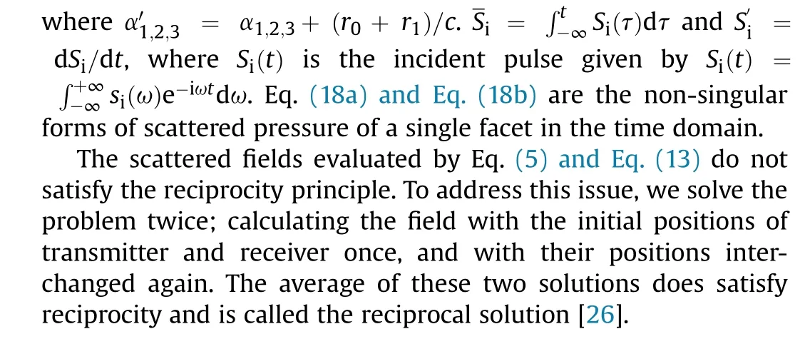
Modeling of bistatic scattering from an underwater non-penetrable target using a Kirchhoff approximation method
2022-07-27BinWangWenhuanWangJunFanKaiqiZhaoFulinZhouLiwenTan
Bin Wang, Wen-huan Wang, Jun Fan, Kai-qi Zhao, Fu-lin Zhou, Li-wen Tan
Collaborative Innovation Center for Advanced Ship and Deep-Sea Exploration, State Key Laboratory of Ocean Engineering, Shanghai Jiao Tong University,Shanghai, 200240, China
Keywords:Kirchhoff approximation Bistatic scattering Time domain Reciprocity Experiment
ABSTRACT A numerical triangulation and transformation into the time domain of a Kirchhoff approximation (KA)method is proposed for the modeling of bistatic scattering from an underwater non-penetrable target.The time domain solution in this approximation can be split up into two parts: the solution of reflected field, contributing around the specular direction, and the solution of shadow radiation, contributing around the forward direction.An average solution in the time domain satisfying the reciprocity principle is presented. The solution is expressed in terms of non-singular functions. The proposed method is validated against a normal mode method for bistatic scattering from a rigid sphere. Moreover, the reflected and shadow highlights on the surface of the sphere are shown to verify the integration surface of the reflected field and shadow radiation. It is also tested against a finite element method and an experiment involving a scaled Benchmark Target Strength Simulation Submarine model.The time-angle bistatic spectra for the model are evaluated by the direct and transformed average solutions of KA, and the former accelerates its speed of calculation. The results are good, and show that this method can be used to predict the bistatic scattered field of a non-penetrable target.
1. Introduction
Bistatic sonar system characterized by the long operating distance, great concealment, and strong anti-interference for the detection and identification of underwater targets has become an important research field in active sonar.The methods for studying bistatic scattering characteristics of underwater targets can be categorized as exact analytic, approximate numerical, and approximate analytic methods.The exact analytic method based on separation of variables is available to calculate both bistatic and monostatic scattered fields of simple-shape targets, such as circle,cylinder, sphere, prolate sphere, and so on [1-3]. At low frequencies, the approximate numerical methods represented by the finite element method [4,5] (FEM) and the boundary element method[6](BEM)can be used to calculate the bistatic pressure of a small target with an irregular shape. They are expected to provide accurate results but are very computationally demanding at high frequencies. In the absence of high-performance computing platforms,however,a solution to such high-frequency problems can be achieved by the approximate analytic method represented by the Kirchhoff approximation[7](KA)method.Based on the KA method,rigid or soft boundary condition is assumed [8] and the scattered field is the sum of contributions of all illuminated facets on the surface of a target.Fawcett[9]used the hybrid Kirchhoff/diffraction method to model high-frequency pulse backscattering from rigid bodies in the time domain, and Lee [10] derived an impulse response from an impedance polygon facet. Fan and Tang [11]proposed the planar elements method to calculate monostatic echo characteristics of sonar targets in the near and far fields.Abawi[12]developed the frequency and time domain solutions of backscattering from non-penetrable targets.Focus on the above-mentioned KA method is mainly put on how to transform the frequencydomain expression to the time domain, and remove singularities of them. Furthermore, the above are based on the classical KA model, which excludes scattering from the shadow region of a target [12]. Although they can be used to calculate the bistatic scattering from the illuminated region of a target, omitting the bistatic scattering from the shadow region yields inaccurate scattered field. He [13] proposed a KA model by combining the Babinet's principle [14,15] and Kirchhoff integral to calculate the forward scattering from underwater targets in the frequency domain.However,the model is not suitable for other bistatic cases.Following Morse[15]and Gaunaurd[16,17],a modified KA method that considers the illuminated and shadow portions was proposed to calculate the bistatic and monostatic scattering cross sections of an impenetrable sphere. Similarly, Ufimtsev [18,19] showed that the scattered field in the Physical Optics approximation can be separated into two components:the reflected field and the shadow radiation. Although the surface integral formula of the KA method to predict the bistatic scattered field is given in detail,the means of numerically implementing it for an irregular-shape target is not.Liu[20] studied the bistatic scattering from an underwater target,where the shadow zone seen by a receiver is added to the modified integral formula.Tan and Wang[21]proposed an acoustic transfer vector (ATV) method to calculate the bistatic target strength of an underwater target, but yields a large error for irregular targets.However, these bistatic methods are given in the frequency domain. The work here develops a similar idea of Gaunaurd [16]with the time-domain numerical implementation to the relevant formula. It can also be seen as a complementary or modified Kirchhoff approximation method to the approach of Abawi [12],where the extension to bistatic scattering from shadow region is not mentioned. Thus, a KA method for the modeling of bistatic scattering from an underwater non-penetrable target is proposed.Its two main features are: (a) a modified KA method applied to bistatic scattering from an irregular-shape target, and (b) a timedomain analytic formula in terms of non-singular functions.
This paper is organized as follows. Sec. II briefly demonstrates how the bistatic scattered field is split up into the reflected field and the shadow radiation by using the Helmholtz integral equation and Kirchhoff approximation, and then presents the corresponding frequency- and time-domain numerical implementations of the equation.In Sec.III,two cases of a sphere and a scaled Benchmark Target Strength Simulation Submarine(BeTSSi-Sub)model[22]are studied to validate the numerical implementations. In Sec. IV, an acoustic scattering experiment involving the BeTSSi-Sub model is conducted and analyzed. Finally, conclusions are drawn in Sec. V.
2. Model derivation
This section introduces the Helmholtz integral equation and Kirchhoff approximation applied to the calculation of the bistatic scattering from a non-penetrable convex target, not involving multiple scattering, and the scattered field can be separated into the reflected field and the shadow radiation. The numerical discretization of the surface of the target into triangular facets, and a frequency-domain formula for the scattering of a triangular facet are also presented.Then,a time-domain formula is obtained via the inverse Fourier transform of the frequency-domain formula. They are similar to Eq. (7) and Eq. (16) of Abawi [12], but extensions to the bistatic case.
2.1. Helmholtz integral equation and Kirchhoff approximation
With the harmonic time dependence of all quantities assumed as exp(- iωt), where ω is angular frequency and t is time. The scattered pressure is expressed by Helmholtz integral equation as
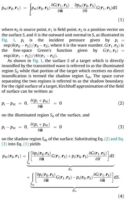
The two terms of Eq. (4) correspond to the decompositions presented by Eq.(1)of Gaunaurd[16]:the first term p,a reflected component,mainly contributes to the backward scattering,and the second term p, shadow radiation, is responsible for the forward scattering.Eq.(4)is equivalent to,but slightly differs from Eq.(8)of Ufimtsev[19].Gaunaurd[16]showed that the integration surface of pis the shadow region of the surface, namely S; Ufimtsev [19]showed that the integration surface of shadow radiation is the surface illuminated by an incident wave, namely S. Clearly, there are different integration surfaces, but the same geometry of the shadow contour. Thus, equality between Gaunaurd and Ufimtsev remains in terms of the value of shadow radiation.This is consistent with the “Shadow Contour Theorem” [19], which states that, “the shadow radiation does not depend on the whole shape of the scattering object, but is completely determined only by the size and the geometry of the shadow contour.”
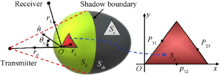
Fig.1. Schematic diagram of sound wave incident on a convex target.
2.2. Numerical discretization and the frequency domain expression
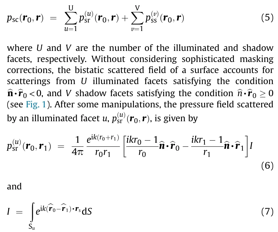
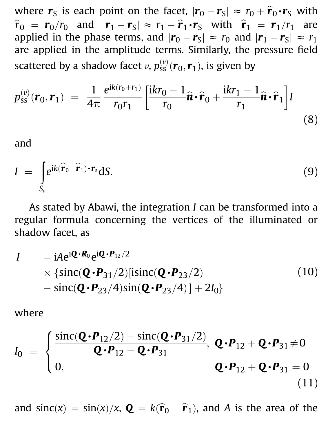
As shown in Fig. 1, the surfaces Sand Sare spatially discretized into triangular facets to obtain the numerical implementation of Eq. (4), and Sand Sdenote the surfaces of an illuminated facet u and a shadow facet v, respectively. The superposition of scatterings from the illuminated and shadow facets is the bistatic scattered field, and then pcan be written as

2.3. Transformation to the time domain expression
A time-domain formula is obtained via an inverse Fourier transform of the frequency domain formula, Eq. (5), as
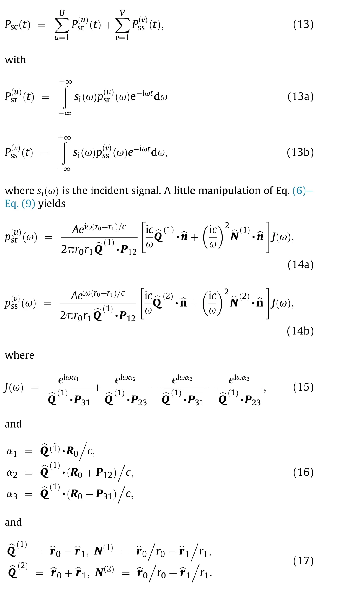
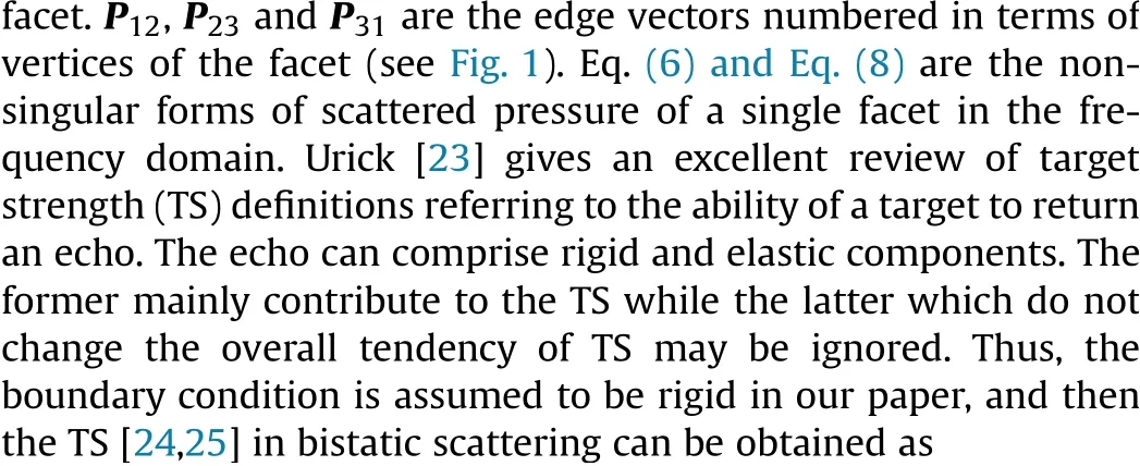
According to the properties of the Fourier transform, it is straightforward to convert Eq. (14) to the time domain with Eq.(13), as
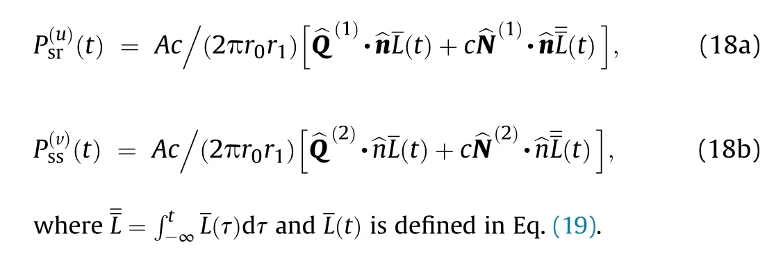
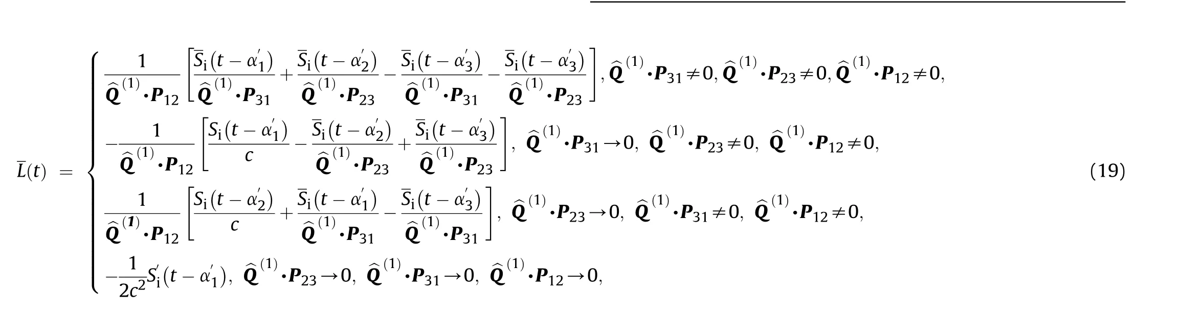

where N is the number of the facets,r=(r,θ,φ)is the receiving point, (θ,φ) are the elevation and azimuth of the incident wave,ris a position vector on the surface S,νis the normal vibrational velocity of the incident wave,and T is given by
3. Numerical results
In this section, we discuss two cases of validation of numerical implementation of the KA method targeted toward an application involving bistatic scattering from a non-penetrable target in the time and frequency domains.The first case analyzes the TS and the time-domain echoes of a rigid sphere for which the normal mode(NM) solution is applied as the reference result. The second case focuses on a scaled BeTSSi-Sub model which is widely used to analyze the acoustic scattering characteristics of submarines. Due to its complex shape, the results of FEM as calculated by the COMSOL Multiphysics software are considered accurate.
3.1. Sphere
Fig.2 shows a sphere of radius a = 1 m,and a transmitter and a receiver are both R = 100 m away from the center of the sphere,where the bistatic angle θ(θ=θ-θ) equals 0or 180corresponding to the backward or forward scattering, respectively.
Using the ATV method [21], the surface of the sphere is also spatially discretized into facets, and the bistatic scattered field is regarded as the sum of scattered waves from facets. Then, the farfield scattered pressure of the sphere can be expressed, as
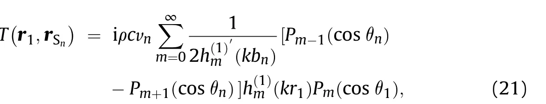
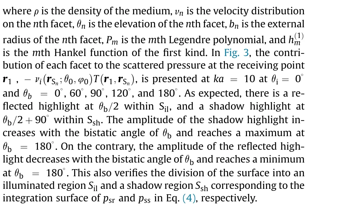
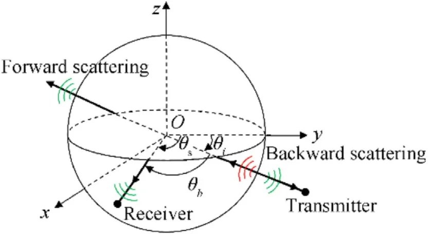
Fig. 2. Bistatic scattering from a sphere.
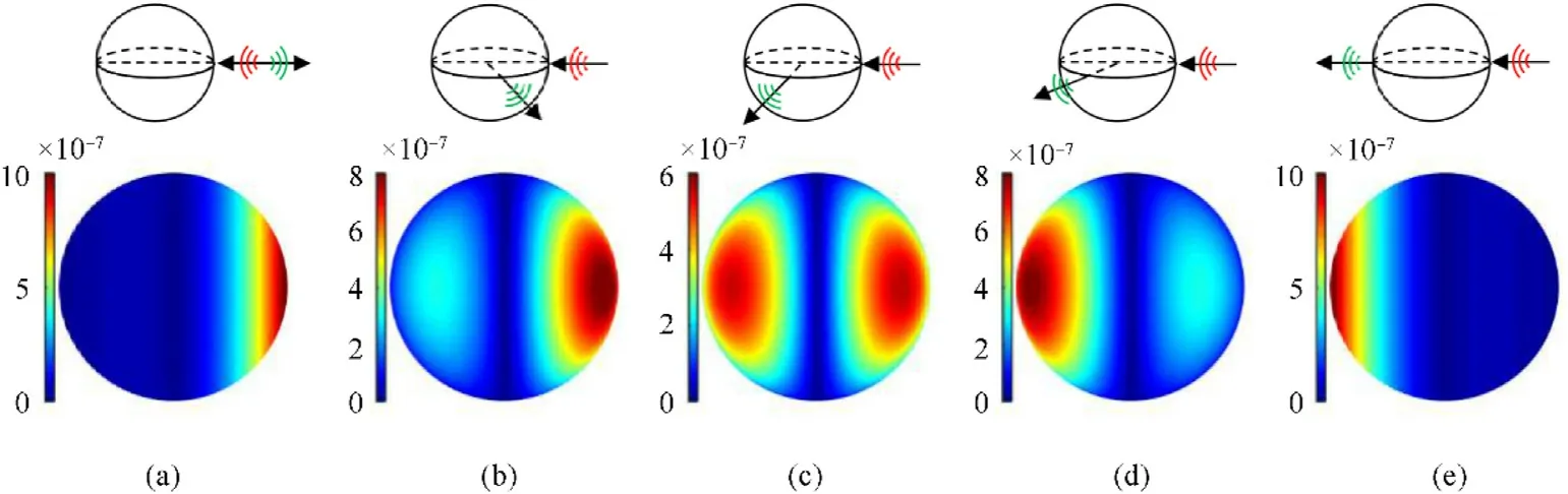
Fig. 3. Contribution of each facet of the sphere to the scattered pressure at the receiving point at ka = 10 at θi = 0° for (a) θb = 0°, (b) 60°, (c) 90°, (d) 120°, and (e) 180°. All values are in Pa.
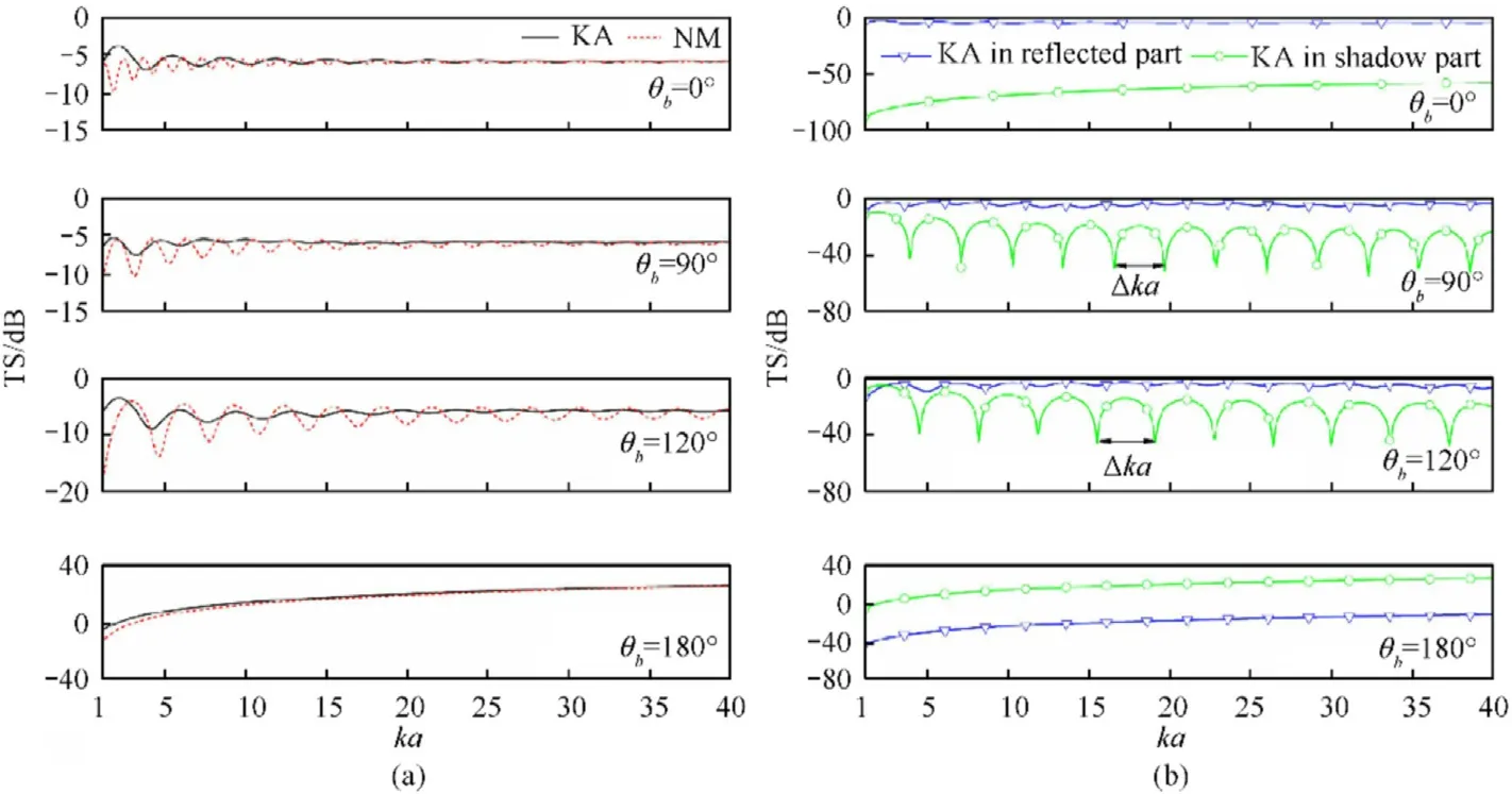
Fig. 4. Comparison of TS of a rigid sphere as a function of ka at θb = 0°, 90°, 120° and 180° (a) between KA and NM, and (b) between KA in reflected and shadow parts.
Fig.4(a)shows a comparison of TS of the bistatic scattering from a rigid sphere between the proposed KA method and the NM solution as a function of ka at θ= 0and θ= 0, 90, 120and 180.As expected,the accuracy of the approximate result increases with frequency.At high ka,the TS calculated by KA is very close to the NM solution. These results show that the Kirchhoff approximation is well implemented for the bistatic scattering at high frequency. Fig. 4(b) compares the TS of KA in reflected and shadow parts. The oscillations in the TS predicted by KA are due to interferences between waves from two highlights. One is the reflected highlight and the other is the shadow highlight.In addition,the oscillations in the shadow region at θ=90and 120in Fig. 4(b) can be interpreted as the co-phased interference of the waves arising in the vicinity of the shadow boundary[19].There are two highlights 1 and 2 on the shadow boundary,as shown in Fig.5.The interference from these two highlights leads to the periodic oscillations, whose period can be obtained as
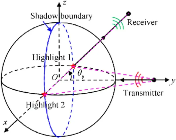
Fig.5. Geometry model of the highlights 1 and 2, the transmitter,and the receiver all lying in the x-y coordinate plane.
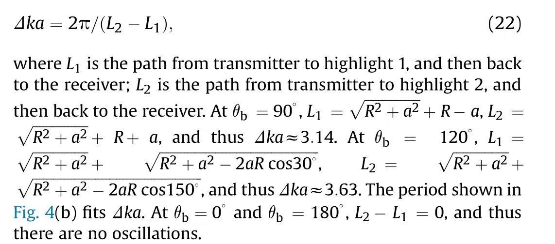
Fig.6(a)shows a comparison of TS of the bistatic scattering from a rigid sphere between the KA method and the NM solution as a function of the bistatic angle θat ka = 40. A good agreement is obtained,and confirms that the proposed KA method can calculate high-frequency scattering from a rigid target at any bistatic angle.The forward scattering produced by a sphere is larger than the backscattering at high frequency. The enhanced TS that bistatic scattering offers is a potential solution to detect stealthy targets.Fig. 6(b) compares the TS of KA in reflected and shadow parts versus the bistatic angle θ. The scattered field calculated by KA is mainly due to the reflected field in the backward direction and the shadow radiation in the forward direction.For increasing θfrom 0to 180,the shadow part increases strongly and becomes the main contribution to the scattered field.At θ= 180,the contribution of the reflected part is so little compared with the shadow part that it can be neglected.
Fig. 6. Comparison of TS of a rigid sphere versus θb at ka = 40 (a) between KA and NM, and (b) between KA in reflected and shadow parts.
Fig.7. Comparison of echoes of a rigid sphere at θi = 0° and θb = 0°,90°,120°,and 180° (a)among direct solution of KA,transformed solutions of KA and NM,and(b)between direct solutions of KA in reflected and shadow parts.
The time-domain direct solution of KA is obtained by Eq. (18),and the transformed solution of KA is obtained by Eq.(6)and Eq.(8)along with fast Fourier transform. A Ricker wavelet with a center frequency of 20 kHz and a pulse width of 0.2 ms is used as the incident pulse. Fig. 7(a) shows a comparison of echoes obtained with the time-domain direct solution of KA, the solution transformed from the frequency-domain solution of KA, and the NM solution at θ= 0and θ= 0, 90, 120and 180. The arrival time of echoes increases with bistatic angle,which corresponds to the positions of highlights in Fig.3.As can be seen,good results are obtained,and show that the KA method is suited to computing the time-domain echoes of a rigid sphere at varying bistatic angles.Fig.7(b)compares the echoes obtained with the direct solutions of KA in reflected and shadow parts. The reflected echoes are negligible in the direction of forward scattering, where the shadow echoes become the main contribution to the scattered field.
3.2. BeTSSi-sub model

Fig.8. Bistatic scattering from a scale BeTSSi-Sub model insonified by the transmitted wave.
Fig.8 shows a BeTSSi-Sub model on the scale of 1:20 consisting of a bow, bow fins, a sail, a cross rudder tail, and a main cylinder hull. A transmitter and a receiver are both 100 m away from the center of the model, where the incident angle θis set to 0(90)corresponding to the bow (broadside) incidence.
Fig.9. Comparison of TS of a rigid BeTSSi-Sub model versus θb at θi = 0°,45°,and 90° (a)among KA1,KA2,KAavg,and FEM,and(b)between KAavg in reflected and shadow parts.
The scattered field calculated by KA generally does not satisfy reciprocity except for spherical targets.To overcome this issue,the scattered field can be calculated twice; once with the initial positions of the transmitter and receiver (KA), and again with their positions interchanged (KA). The average of these two fields(KA) satisfies reciprocity. Fig. 9(a) shows a comparison of TS of the model among KA, KA, KA, and FEM versus the bistatic angle θat the incident angle of θ= 0, 45, and 90and f =15 kHz. Good results are obtained; however, the agreement between KAand FEM is somewhat better. Moreover, the KAsatisfies reciprocity. At varying incident angles, the TS always maximizes in the direction of forward scattering due to the shadow radiation. At θ= 45and θ= 90, there appears a secondlargest TS due to the specular reflection of the hull. At θ= 90,the monostatic TS in abeam is the second largest value due to the reflected part. Fig. 9(b) compares the TS of KAin reflected and shadow parts versus the bistatic angle θat θ= 0,45,and 90.For increasing θ, the shadow part decreases strongly from 0to 180,and increases strongly from 180to 360.In the vicinity of the direction of forward scattering,the shadow radiation is much larger than the reflected field,so the latter can be negligible.In the vicinity of the directions of backscattering and specular reflection, the shadow radiation is much lower than the reflected field, so the latter mainly contributes to the scattered field.
Fig.10. Comparison of the time-angle spectra of echoes of a rigid BeTSSi-Sub model versus θb. Top panels: direct solutions of KAavg at (a) θi = 0°, (b) 45°, and (c) 90°. Bottom panels: transformed solutions of KAavg at (d) θi = 0°, (e) 45°, and (f) 90°.
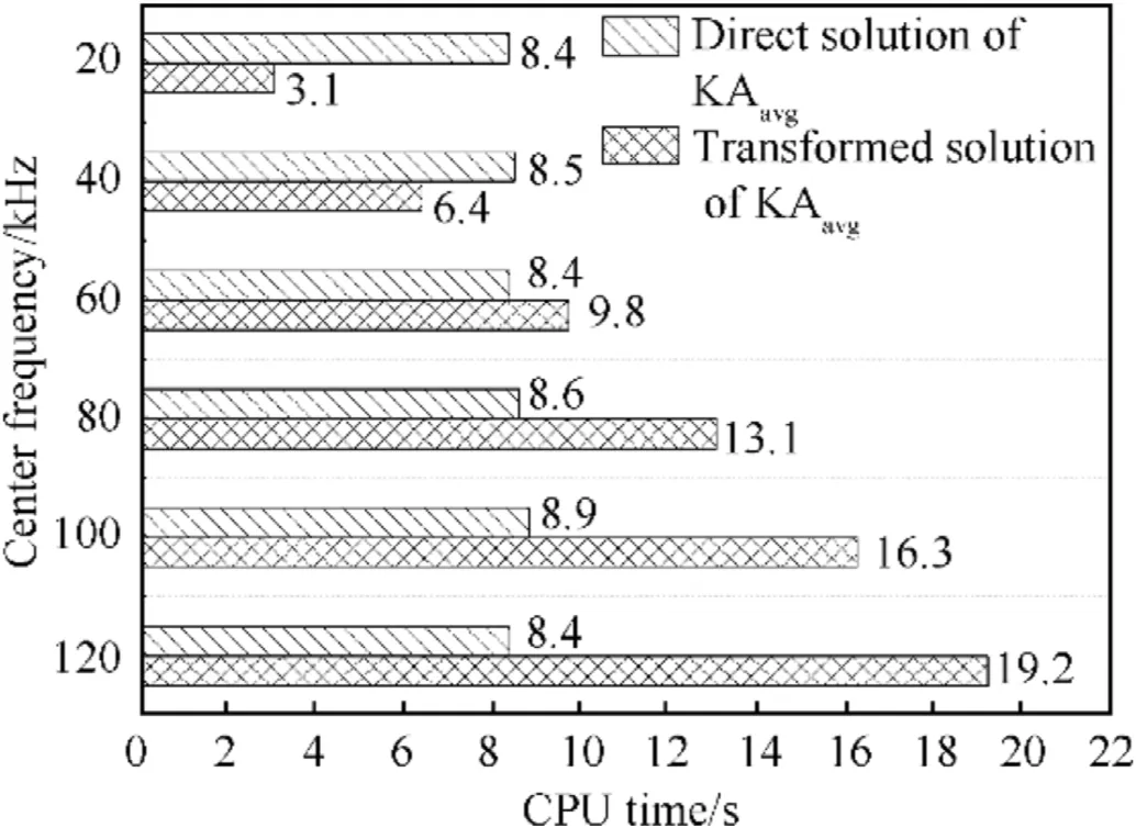
Fig. 11. Comparison of CPU time between the direct and transformed solutions of KAavg.
The 60-kHz Ricker wavelet is incident on the rigid BeTSSi-Sub model, and then its time-domain echoes are calculated by the direct and transformed solutions of KA. Fig. 10 shows a comparison of the time-angle spectra of echoes between the direct solution of KAand the transformed solution of KAat the incident angle of θ= 0, 45, and 90. There is an excellent agreement between these two solutions.Moreover,the geometrical highlight curves of the bow, bow fins, tail fins, and sail plotted in Fig.10(a)-Fig.10(c) are consistent with these highlights obtained with the direct solution of KAin occurring time and shape, but the former cannot forecast the values.
Fig.11 shows a comparison of CPU time between the direct and transformed solutions of KAfor calculating the time-domain echo of the model at θ=0and θ=0with the increasing center frequency. For the center frequency exceeding 60 kHz, the transformed solution takes more CPU time as compared to the direct solution. Moreover, the CPU time consumed by the latter remains steady.It is attributed to different numerical algorithms for the implementation code:inverse Fourier transform applied in the transformed solution, and shift algorithm independent of the frequency applied in the direct solution. These results show that the use of the direct solution of KAis better suited to computing the high-frequency broadband echoes than the transformed solution.
4. Experimental results
To verify the effectiveness of the proposed method and the accuracy of the numerical results, we carried out an acoustic scattering experiment on a scaled BeTSSi-Sub model at the Duihekou reservoir. The experimental plot has an outstanding geographical location with a calm and open surface.The average water depth is 14 m. The experimental submarine is hollow and air-filled. The single-layered model has been machined with stainless steel, and the thickness of its components is shown in Table 1. Given that specular reflection is the main basis for parameter configuration of multistatic sonar in the detection of underwater targets,and given that rigid scattering mainly contributes to the specular reflection of our experimental model at high frequency,and the influence from elastic scattering is not significant, the model could be approximated as a rigid target.Except for two hanging points A and B,the model here is the same as the model shown in Section 3.3. The experimental and geometric models are illustrated in Fig.12. The experimental setup is shown in Fig. 13. The experimental object spins around its axis at 0.5/s in sequence, and is controlled by a mechanical turntable, whereas the transmitter and receiver are fixed.The range of frequency of the transmitter is 40-80 kHz,and the receiver is a Reson TC4032 hydrophone operating over a frequency range of 5 Hz-120 kHz,with a receiving sensitivity of-170 dB re 1V/μPa. The entire measurement system is powered by an uninterrupted power supply to remove AC interference.
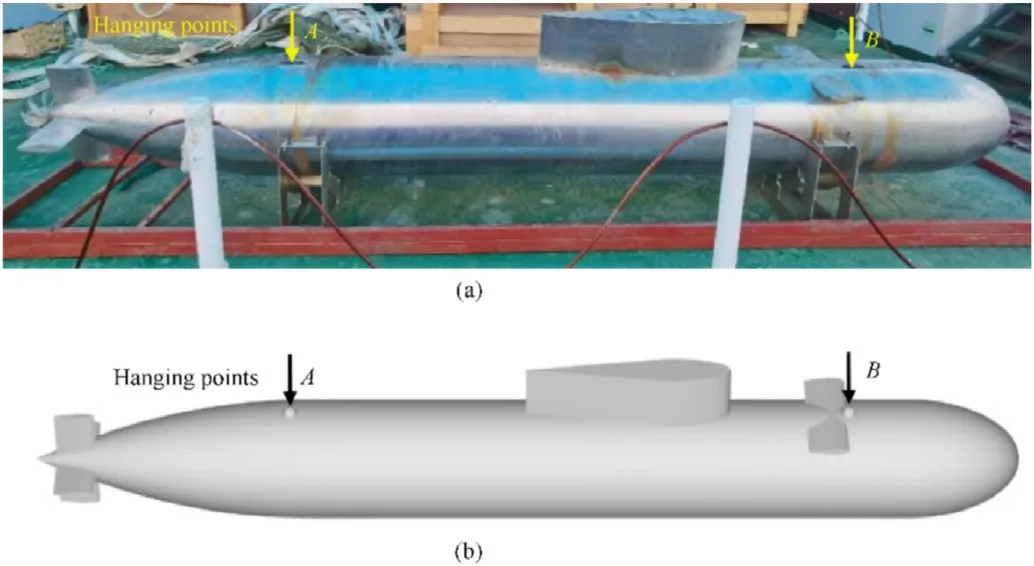
Fig.12. The BeTSSi-Sub model: (a) experimental model, (b) geometric model.
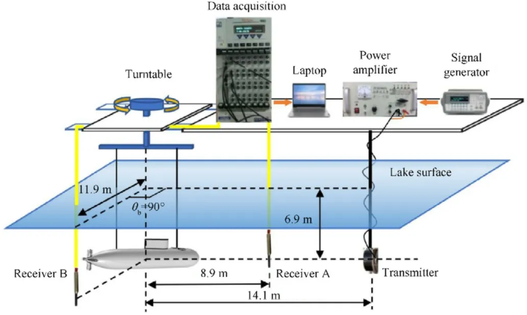
Fig.13. The experimental setup.
The transmitted wave is constructed as a segment of linear frequency modulation signal in the range of 40-80 kHz, with a pulse width of 2.5 ms and a burst period of 500 ms to achieve long and steady-state measurements. To improve the signal-to-noise ratio and distance resolution of the echoes, a matched filtering technology is conducted. Fig.14 shows a comparison of the timeangle spectra of echoes of the BeTSSi-Sub model between the direct solution of KAand experiment at θ=0and 90. Good results are obtained, but a slight difference can be observed in the experimental results due to noises. The geometrical highlight curves of the bow, bow fins, tail fins, sail, and two hanging points match these highlights obtained with the direct solution andexperiment in occurring time and shape.

Table 1 Geometric parameters of the experimental model.

Fig.14. Comparison of the time-angle spectra of echoes of a BeTSSi-Sub model versus θi.Top panels:direct solutions of KAavg at(a)θb = 0° and(b)90°.Bottom panels:results of experiment at (c) θb = 0° and (d) 90°.
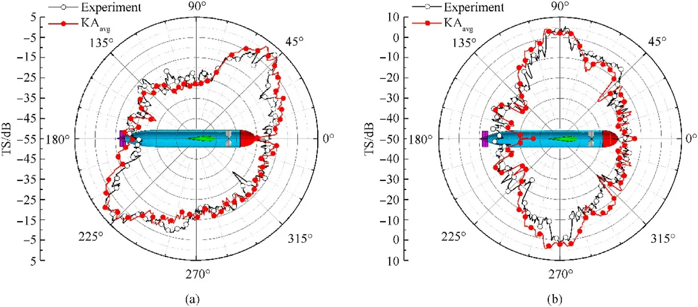
Fig.15. Comparison of TS of a BeTSSi-Sub model between KAavg and experiment versus θi at f = 60 kHz for (a) θb = 0° and (b) 90°.
Fig. 15 shows a comparison of the TS obtained with the KA method and experiment as a function of the incident angle θat θ=0and 90and f = 60 kHz.In the cases of θ=90and 270and θ= 0, and θ=45and 225and θ= 90, the specular reflection of the hull mainly contributes to the scattered field, and provides a maximum TS.The agreement between the results of the KAand experiment is good.The slight difference between them can be observed in the vicinity of θ=180and θ= 0, and θ=135and θ= 90, because KAneglects the multiple scatterings from the propeller of the model.
5. Conclusions
This study proposes a KA method to derive the time-domain formula for the bistatic scattering from an underwater nonpenetrable target. The bistatic scattered field can be split up into the reflected field that mainly contributes around the directions of backscattering and specular reflection, and the shadow radiation that mainly contributes around the direction of forward scattering.The reflected field and the shadow radiation are regarded as the sum of contributions of the illuminated and shadow facets,respectively. Moreover, an average KA solution proposed does satisfy reciprocity. The solution is expressed in terms of nonsingular functions, and by different expressions for several limiting cases.
The method has been validated by two cases.One is the bistatic scattering from a rigid sphere where the NM solution can be obtained. The reflected and shadow highlights on the surface of the sphere are given to verify the integration surface of the reflected field and shadow radiation.The other is the bistatic scattering from a rigid BeTSSi-Sub model where the results of FEM and experiment exist. By the time-angle spectra for bistatic scattering from the model, the curves of highlight are analyzed, and show that the acoustic scattering contributions of bow,bow fins,tail fins,and sail build the main echo characteristics of the model.Results have been shown to be good for bistatic scattering from a non-penetrable target at high frequency. They also show that the direct solution is more efficient than the transformed solution in the time domain,and can potentially be extended to the doppler echo. Our future work in the area will extend the proposed method to the modeling of bistatic scattering from a moving transmitter,receiver,or target in the time domain.
The authors declare that they have no known competing financial interests or personal relationships that could have appeared to influence the work reported in this paper.
The authors would like to acknowledge the Oceanic Interdisciplinary Program of Shanghai Jiao Tong University (project number SL2021PT108). The data was obtained with the help of laboratory technicians Kai Xv,Ye-feng Tang,and Ming-da Li.We wish to thank the reviewers for their constructive and helpful comments.
杂志排行

Defence Technology的其它文章
- A new model for the expansion tube considering the stress coupling:Theory, experiments and simulations
- Experimental and analytical assessment of the hypervelocity impact damage of GLAss fiber REinforced aluminum
- Effect of the microporous structure of ammonium perchlorate on thermal behaviour and combustion characteristics
- 3,6-bis (2,2,2-trinitroethylnitramino)-1,2,4,5-tetrazine. Structure and energy abilities as a component of solid composite propellants
- Rapid preparation of size-tunable nano-TATB by microfluidics
- Mechanical behavior of Ti-6Al-4V lattice-walled tubes under uniaxial compression