Design of Thomson scattering diagnostic system on linear magnetized plasma device
2022-07-13MengmengXU徐梦梦QiaofengZHANG张乔枫andJinlinXIE谢锦林
Mengmeng XU(徐梦梦),Qiaofeng ZHANG(张乔枫) and Jinlin XIE(谢锦林)
1 Department of Plasma Physics and Fusion Engineering,School of Nuclear Science and Technology,University of Science and Technology of China,Hefei 230026,People’s Republic of China
2 CAS Key Lab of Geoscience Environment,School of Earth and Space Sciences,University of Science and Technology of China,Hefei 230026,People’s Republic of China
Abstract In addition to the magnetic confinement fusion plasma,Thomson scattering has been applied to measure electron density and temperature of low-temperature plasmas.Based on a linear magnetized plasma device,a set of Thomson scattering diagnostic system is designed to diagnose the plasma withne=101 8-101 9m-3 andTe=2- 5eV.Due to low plasma temperature and density,this diagnostic system needs high spectral resolution and collection efficiency to meet the requirements of electron velocity distribution function measurements.Through the bench test,it is confirmed that the spectral resolution reaches 0.01 nm,and theoretical collection efficiency is high enough to obtain a Thomson scattering spectrum by 1000 accumulations.
Keywords: Thomson scattering,low temperature plasma,EVDF
1.Introduction
As an active and non-intrusive diagnostic technique,Thomson scattering (TS) is the most reliable method to measure electron temperature or velocity distribution with high temporal-spatial resolution.Since Peacock first applied Thomson scattering in tokamak plasma in 1969 [1],it has been widely used to measure electron temperatureTeon major tokamaks such as EAST [2],DIII-D [3],ASDEX [4],JT-60U [5],HL-2A[6],etc.In recent decades,the TS application scenario has been extended from the traditional highTemeasurement in fusion plasmas to the low-temperature plasmas,e.g.glow discharge [7],inductively coupled plasmas [8],argon microwave plasmas [9] and Hall thruster [10].These plasma sources are characterized by very low electron temperature in the order of several eV and low density ranging from 1016to 1019m-3.Due to the low plasma density and electron temperature,the challenges are the low scattering signal intensity and the narrow spectral width.
In this work,a set of incoherent Thomson scattering diagnostic system has been designed for the Linear Magnetized Plasma (LMP) device in USTC.The main research topics of LMP are focused on fundamental plasma physics,such as drift instability,wave-particle interaction,magnetic field reconnection problems [11].Apparently,the diagnostic of electron dynamics is very important for these experimental researches.For example,the heating and acceleration of electrons during the magnetic reconnection process is still a hot research topic [12].Compared with traditional Langmuir probes and other diagnostics,Thomson scattering is a better choice which is capable of performing theTeand even the electron velocity distribution function(EVDF)measurements with high temporal and spatial resolution.
The LMP TS system consists of a Nd:YAG pulsed laser and a grating spectrometer with an intensified CCD (ICCD).Theoretically,the TS spectrum FWHM is 5.54 nm taking the typical LMPTevalue as 5 eV,thus it requires the spectral resolution to be less than 0.01 nm.The capability of the TS system has been verified through the bench test,the results of Rayleigh and rotating Raman scattering are also presented.
2.Experimental setup
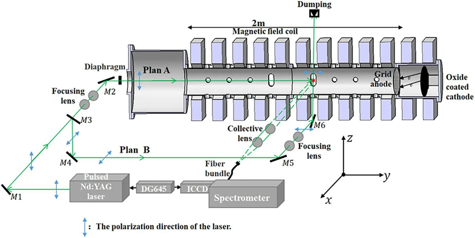
Figure 1.Experimental setup of the TS system on the LMP.
The vacuum chamber of LMP is surrounded by 12 sets of magnetic field coils,which generate a steady-state magnetic field varying from 180 to 1000 Gs which is used to confine the diffusion of plasma from the source to the experimental region.The experimental region is 2 m in length and 0.25 m in diameter.LMP operates in an oxide-coated cathode [13]pulse discharge mode with 1 Hz repetition frequency and a duration time from 10 to 20 ms.The typical plasma parameters are A electron density of1017-1019m-3and electron temperature of 2-5 eV.
The incident laser is provided by a Quanta-Ray Nd:YAG laser operating at its second harmonic mode with a 30 Hz repetition frequency.The laser pulse length is 10 ns,the maximum energy of one pulse is 500 mJ.Although the number of the scattered photons with an incident laser at 1064 nm will be twice the number with a laser at 532 nm,the quantum efficiency at 532 nm of the ICCD with Gen III intensifier is much higher than the quantum efficiency at 1064 nm,which is the reason that the laser is set working at its harmonic mode.
As shown in figure 1,there are two TS diagnostic settings for EVDF measurements.For configuration A,the direction of the incident laser is along the y-axis and the polarization direction is along the z-axis.For configuration B,the incident laser is propagated along the z-axis and polarized in the y-direction.In both schemes,the scattered photons are collected along the x-direction which ensures the TS differential cross-section reaches its maximum.According to the definition of scattering factor,where k is the scattering vector,λDis the Debye length andk0is the wavenumber of the incident laser,the scattering factor α for our experiments is around 0.001,which satisfies the incoherent Thomson scattering conditionα≪1[14].
The laser incident optics consists of 10 transmission mirrors and a set of focusing lenses including a planoconcave lens with −200 mm focal length and a planoconvex lens with 200 mm focal length.The focusing lens set is used to reduce the beam width from 9.5 mm at the exit portal to 2 mm in the detection region.The overall transmission efficiency of the incident optics is about 54%.
The collective lens group adopts two lenses with 50 mm in diameter,the focal lengths are 250 mm and 500 mm.The collecting solid angle is 6.25×10⁻⁴sr and the transmittance of the lens group is 76%.Then the scattered photons are transmitted by the optical fiber with input numerical aperture of 0.22.The fiber bundle consists of 19 single fibers with 200μm in diameter and the transmissivity is 77%.The fiber bundles are stacked in a circle with a diameter of 1 mm in the receiving plane,and are reorganized to 1×19 to match the entrance slit of the spectrometer.The spectrometer has a 2400 l mm−1grating with a size of 76 mm×76 mm and the spectral dispersion is 0.53 nm mm−1at 500 nm.The diffraction efficiency of grating is around 80%.The total transmission efficiency of the collection system is estimated at 45%.The array format of the ICCD is 1024×1024 and each pixel size is 13μm ×13μm.The quantum efficiency of the image intensifier at 532 nm is 49%.
The total collected TS photons for one laser pulse can be estimated according to the formula
Hereis the total number of collected scattered photons,is the maximum of the TS differential cross-section wherereis the classical electron radius,neis the plasma density,ΔL is the length of the scattering volume,NLis the number of incident photons,A is the total system transmission efficiency andΔΩ is the solid angle of collection optics.The maximum of the TS differential cross-section can be written as.Considering the typical LMP TS case withne=1019m-3and ΔL=2 mm,the total number of scattered photons received by the ICCD will be=32photons.
In order to improve the signal-to-noise ratio,the stray light photons need to be suppressed.The beam dump is mounted at the laser output end and the internal surface of the LMP vacuum chamber is covered with black foils.In addition,a narrow baffle is placed between the spectrometer and the ICCD to block the light with a wavelength close to 532 nm.

Figure 2.The timing schematic of the TS system.
Since the repetition frequencies of the plasma source and the incident laser are different,the operation sequences of each instrument should be carefully tuned to make sure the TS diagnostic system works correctly in the expected time period for every plasma pulse.The timing sequences of the trigger signals are shown in figure 2.The master trigger signal is a 1 Hz Transistor-Transistor Logic signal,which is provided to the plasma discharge controller and a function generator.The function generator outputs a 30 Hz signal to digital delay generator DG645.Then DG645 provides the trigger signals for the pulsed laser and ICCD with different time delays.The laser output time is set at t=5 ms when the plasma column has been steadily established.The time delay of the laser flash lamp and Q-switch is set to near 210μs for best laser output.Due to the finite optical path and instrument response time,the delay time between the Q-switch and ICCD is adjusted to 122 ns,which is optimized via the in situ monitoring of laser signal by photodiodes.Considering the laser pulse length is 10 ns,the ICCD gate open time is set to 20 ns,which is the detector integrating period.
3.Bench test
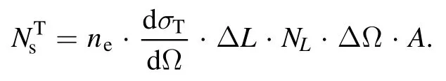
The performances of the spectrometer and ICCD are calibrated by the sodium lamp which has two characteristic lines at 589 nm and 589.6 nm.The spectrum shown in figure 3(b)is obtained by the summation of the intensities along the vertical direction.Based on the pixel number between the two peaks,the spectral dispersion is 0.45 nm mm−1corresponding to a spectral resolution of 0.006 nm.The spectral measurement range is around 6 nm (1024×0.006),which is larger than the FWHM of the TS spectrum withTe=5eV.The measured line broadening is around 0.033 nm,which is dominated by the instrument broadening of the spectrometer.
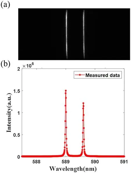
Figure 3.(a) ICCD imaging,(b) the spectrum of the sodium lamp.
Rayleigh scattering is conducted when the LMP chamber is filled with pure nitrogen.The spectra at different filling pressures are shown in figure 4(a).The spectrum under one bar is obtained within only one laser pulse due to the high molecular density.The RS spectral width is estimated as 0.048 nm,which is the convolution of laser linewidth and instrument broadening.By changing the neutral pressure of nitrogen in the chamber,it is clearly shown that the total scattering intensity is proportional to the nitrogen density.As shown in figure 4(b),a narrow baffle is added in front of the ICCD to filter out Rayleigh scattering and stray light photons.The baffle with 2 mm width and 0.3 mm thickness is made of black aluminum alloy,and the transmittance function has a notch of 0.8 nm around 532 nm shown in figure 4(d).With the baffle installed,the Raman scattering spectrum of the nitrogen is obtained with 30 accumulations at a filling pressure one bar,shown in figure 4(c).The measured spectrum is consistent with the simulated spectrum based on a rotational Raman scattering model of the nitrogen [15].
According to table 1,the intensity of Raman scattering in N2is 20 times stronger than Thomson scattering intensity on LMP.It is expected that the TS diagnostic will need around 600 accumulations to get a clear broadened spectrum in theory.
4.Summary
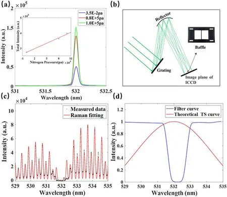
Figure 4.(a) Rayleigh scattering spectrum ofN.2 (b) Schematic diagram of filter baffle.(c) Raman scattering spectrum ofN.2 (d)Transmittance of filter baffle near 532 nm.
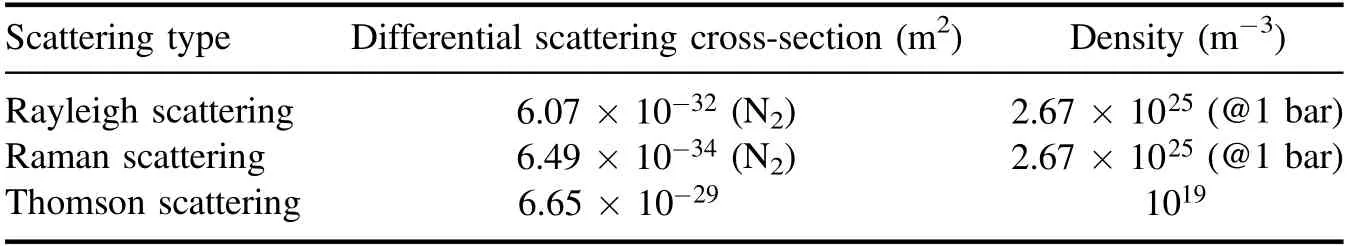
Table 1.Differential scattering cross-section and number density.
A TS diagnostic system has been designed on an LMP device,which is expected to provide EVDF measurements for the oxide-coated cathode plasma source withTe=2- 5eV andne=1018-1019m-3.The spectrometer system has been characterized using a sodium lamp,and a baffle is added to the spectrometer as a notch filter.Both Rayleigh scattering and Raman scattering have been conducted,which verifies that the system has the ability to obtain a TS spectrum with 600 accumulations in this case.
猜你喜欢
杂志排行
Plasma Science and Technology的其它文章
- Investigation on the multi-hole directional coupler for power measurement of the J-TEXT ECRH system
- Neutronic analysis of Indian helium-cooled solid breeder tritium breeding module for testing in ITER
- Investigation on the electrode surface roughness effects on a repetitive selfbreakdown gas switch
- Roll-to-roll fabrication of large-scale polyorgansiloxane thin film with high flexibility and ultra-efficient atomic oxygen resistance
- Effect of shock wave formation on propellant ignition in capillary discharge
- The application of a helicon plasma source in reactive sputter deposition of tungsten nitride thin films