Roll-to-roll fabrication of large-scale polyorgansiloxane thin film with high flexibility and ultra-efficient atomic oxygen resistance
2022-07-13YiLI李毅ZhonghuaLI李中华DetianLI李得天YanchunHE何延春ShengzhuCAO曹生珠HuWANG王虎HengjiaoGAO高恒蛟HanjunHU胡汉军YingHE贺颖YuanWANG王媛andJunZHU朱俊
Yi LI (李毅),Zhonghua LI (李中华),Detian LI (李得天),Yanchun HE (何延春),Shengzhu CAO (曹生珠),Hu WANG (王虎),Hengjiao GAO (高恒蛟),Hanjun HU (胡汉军),Ying HE (贺颖),Yuan WANG (王媛)and Jun ZHU (朱俊)
1 Science and Technology on Vacuum Technology and Physical Laboratory,Lanzhou Institute of Physics,China Academy of Space Technology,Lanzhou 730000,People’s Republic of China
2 School/Hospital of Stomatology School/Hospital of Stomatology Lanzhou University(Dental Hospital).Key Laboratory of Dental Maxillofacial Reconstruction and Biological Intelligence Manufacturing,Gansu Province,School of Stomatology,Lanzhou University,Lanzhou 730000,People’s Republic of China
3 State Key Laboratory of Advanced Display Technology,Special Display and Imaging Technology Innovation Center of Anhui Province,Anhui Provincial Key Laboratory of Advanced Functional Materials and Devices,Academy of Opto-Electric Technology,Hefei University of Technology,Hefei 230009,People’s Republic of China
Abstract One of the most widely used and well-established atomic oxygen(AO)protection solutions for low Earth orbit(LEO)satellites is the deposition of protective coatings on polymeric materials.However,manufacturing extensive expanses of these coating materials with good transparency,flexibility,smoothness,ultra-thinness,and exceptional AO resistance remains a critical issue.Herein,we successfully deposited a 400 nm thick polyorgansiloxane (SiOxCyHz) coating with high optical transparency and uniform good adherence on to a 1.2 m wide polyimide surface,by optimizing the distribution of hexamethyldisiloxane and oxygen as precursors in the roll-to-roll compatible plasmaenhanced chemical vapor deposition process.After AO irradiation with the fluence of 7.9×10²⁰ atoms·cm-2,the erosion yield of the SiOxCyHz-coated Kapton was less than 2.30×10⁻²⁶ cm3·atom-1,which was less than 0.77%of that of the Kapton.It indicates that the SiOxCyHz coating can well prevent the erosion of Kapton by AO.In addition,it was also clarified that a SiO2 passivation layer was formed on the surface of the SiOxCyHz coating during AO irradiation,which exhibited a ‘self-reinforcing’ defense mechanism.The entire preparation process of the SiOxCyHz coating was highly efficient and low-cost,and it has shown great potential for applications in LEO.
Keywords: plasma-enhanced chemical vapor deposition,hexamethyldisiloxane,polyorganosiloxane thin film,flexibility,atomic oxygen
1.Introduction
Due to their characteristics of being lightweight,with flexibility,good wear resistance,and thermal optical properties,polymer materials,particularly Kapton and other polyimides,are commonly employed in spacecraft.With the advancement of science and technology,there is an increasing number of spacecraft,notably the space station,that travel in a low Earth orbit(LEO)space environment.However,spacecraft exterior materials are exposed to atomic oxygen (AO),ultraviolet(UV),ionizing radiation,thermal cycle,micrometeoroids,orbital debris,and charged particle bombardment in LEO[1-3].It is generally understood that AO with an effective energy of around 5 eV and flux of 1014-1015atom·cm−2·s−1in LEO can cause irreversible damage to organic materials,including mass loss and alterations in optical,mechanical,electrical,and chemical characteristics [4,5].
However,no commercially available organic materials can tolerate AO erosion by themselves.The most well-characterized AO erosion yield is that of Kapton®H,which exhibits a (3.0±0.07)×10-24cm3·atom-1erosion yield for 4.5 eV AO [3].In LEO,a 25 μm thick Kapton blanket,for example,would entirely degrade within 6 months [1,6,7].Fortunately,the deposition of protective coatings on the surface of the spacecraft exterior materials is one of the most extensively used and well-established AO protection solutions for LEO spacecraft.
Various types of inorganic and organic protective coatings have been established during the last few decades,for example,SiO2coating,SiOxfilm,multilayer SiO2/Al2O3films,and so on[8-11].Despite inorganic protective coatings offering great AO resistance and being uncomplicated to fabricate onto the surface of a polyimide,under AO and UV irradiation however,the hydrophilic inorganic coatings are not covalently bound onto the hydrophobic surface of a polyimide and are prone to cracking and peeling [8,9].Furthermore,the thermal expansion coefficient of these inorganic coatings differs noticeably from that of polymers,and they are susceptible to splitting after continuous thermal cycle exposure.When the protective atomic oxygen covering is destroyed,AO attacks and erodes the underlying organic material via scratches,cracks,and erosion.
In recent years,organic-inorganic hybrid protective materials have received much interest as a new class of nanocomposite materials,because they have the following advantages: inorganic materials have rigidity and high thermal stability,and organic polymers have flexibility,high dielectric constant,ductility,and processability [12,13].Polymeric organosilicon thin films have the advantage of combining the chemical inertia of organosilicon compounds with excellent homogeneity and adhesion to the substrate of polymer thin films [14].As a result,these polymeric organosilicon compounds have a wide range of applications,including protective coatings,sensor coatings,integrated optics,biomedical applications,selectively permeable membranes,vapor barriers,adhesion promotion,etc [14,15].
Plasma-enhanced chemical vapor deposition (PECVD)has the advantages of a simple preparation process and low working temperature and is a commonly used technique for preparing films by plasma polymerization.Compared to other preparation methods,PECVD-deposited AO protective coatings are amorphous,highly cross-linked,compact,pinholefree,have strong adhesion to flexible organic substrates,and have better physicochemical stability [16-18].Therefore,polymeric organosilicon protective coatings prepared by the PECVD process using silicon-based precursors have received a lot of attention.We have developed,to an early stage,a polyorgansiloxane (SiOxCyHz) atomic oxygen protective film using the PECVD method,which has the advantages of homogeneity and no defects such as cracks and pinholes,and excellent atomic oxygen resistance.However,the width of this SiOxCyHz-based Kapton was only 0.5 m,which limits the protection it can offer for organic materials in larger areas.In addition,the AO erosion mechanism on the SiOxCyHzprotection film has not been well elucidated.
In this study,a SiOxCyHzprotective coating with a high degree of uniformity was prepared on a large area polyimide(1.2 m wide) substrate using an improved roll-to-roll compatible PECVD preparation process with an orthogonal gas distribution method.The adhesion of the protective coating to the substrate,the optical transmittance,and the resistance to AO erosion was investigated.In addition,the effects of surface morphology,microstructure,optical properties,and chemical composition of the pristine and SiOxCyHzcoated Kapton before and after AO irradiation were investigated in depth.Finally,the erosion/protection mechanism of SiOxCyHzcoatings in a space environment was also proposed.This work provides an effective method for the design and preparation of large-area flexible protective coatings with excellent AO resistance properties.
2.Experimental section
2.1.Materials
The polyimide,a commercial Kapton film (Kapton H,25 μm thickness,1.2 m wide),was purchased from Dupont Co.Hexamethyldisiloxane (HMDSO,(CH3)3Si-O-Si(CH3)3,99.97%) was purchased from Sigma-Aldrich.Oxygen and Nitrogen were purchased from Lanzhou Zhou Li Chemical Gas Co.
2.2.Fabrication of SiOxCyHz protective coating
Roll-to-roll compatible plasma-enhanced chemical vapor deposition(PECVD)equipment was used to deposit a plasma polymerized SiOxCyHzcoating onto a Kapton substrate,utilizing HMDSO and O2as monomers.The preparation procedure was as follows.(1)The Kapton with a width of 1.2 m was put into the vacuum chamber of the PECVD equipment and the vacuum chamber was pumped to 4×10⁻³Pa.(2)The container containing the HMDSO monomer was heated in a water bath to 35°C so that the liquid HMDSO monomer became a vapor.The HMDSO monomer gas,with a flow rate of 30 sccm,was mixed with oxygen with a flow rate of 50 sccm and then added into the vacuum chamber,while controlling the working pressure of the vacuum chamber at 5 Pa.The concentration of the gas mixture of HMDSO and oxygen was normally distributed in the direction of motion of the Kapton substrate,that is,the concentration of the gas mixture increases first and then decreases in the direction of rotation of the polyimide substrate.(3)Set the travel speed of the polyimide substrate in the vacuum chamber to 37 mm min−1and the chamber discharge power to 400 W.The gas mixture in the vacuum chamber was ionized and deposited onto the moving polyimide substrate,and a SiOxCyHzprotective coating with an average thickness of about 400 nm was fabricated onto the surface of the polyimide substrate after passing through the vacuum chamber.The SiOxCyHzcoating was deposited onto the surface of the glass and Al substrate by taping the glass slice and aluminum film onto the polyimide film in the above experimental procedure.The thickness of the SiOxCyHzcoating on the glass or Al substrate was the same as that of the coating on Kapton.
2.3.Atomic oxygen exposure experiments
The ground-based tests of AO erosion were carried out in a space environment simulator established at the Lanzhou Institute of Physics (Lanzhou,China) [19].Based on a previously characterized LEO erosion yield (3.00×10⁻²⁴cm3·atom−1),Kapton H film was utilized to determine the AO flux [1,3].The average energy of the AO was produced as 5 eV,and the flux of AO was determined to be 1.98×10¹⁶atoms·cm−2·s−1.A vacuum of 10 Pa was maintained throughout the exposure.The mass loss after irradiation tests was used to calculate the AO erosion yield of the samples,which was estimated using equation (1)

where E,AO erosion yield,is the volume loss per incident oxygen atom,cm3·atom−1; ΔM is the accumulated mass loss of the sample,g; A is the radiation exposure area of the sample,1.21 cm2;and ρ is the density of the sample,g·cm−3.The density of the as-prepared SiOxCyHzsample was about 1.70 g·cm−3; F is the accumulated AO flux,atoms·cm−2.
2.4.Characterization
FTIR-ATR spectra ranging between 400 and 4000 cm−1were recorded by an IFS-66/S Bruker spectrophotometer.The elemental composition of the samples was analyzed by x-ray photoelectron spectroscopy (XPS,ESCALAB 250) after sputtering with an Ar+beam for 10 s,and the fitting of the peaks was done using the MultiPak software with a linear background assumed.The binding energies of each of the spectra were calibrated with C1s at 284.6 eV.The morphology and interfaces of the samples were investigated by scanning electron microscopy(SEM-S4800)and atomic force microscopy(AFM).The UV-vis spectra of the samples were obtained using a UV-vis spectrophotometer (U-3900H,HITACHI,Japan).We designed our own mode of adhesion test.The making process is as follows.The SiOxCyHz/Kapton film was adhered to a standard tape (610 # 3 M) in a certain pressure condition.When the 3 M tape was removed from the film (nominal peel strength: 0.47 N mm−1),the surface morphology of the film was analyzed by SEM.
3.Results and discussions
3.1.Characterization of SiOxCyHz coating
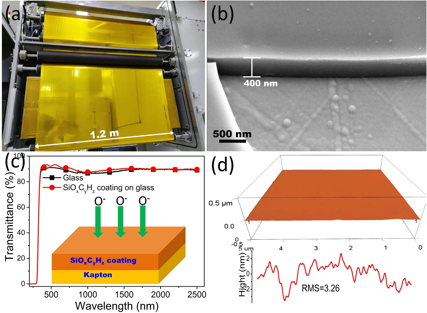
As shown in figures 2(a) and S1 (available online at stacks.iop.org/PST/24/065505/mmedia) in the supporting information,we improved the roll-to-roll compatible PECVD process to prepare a large-area flexible polyorgansiloxane(SiOxCyHz) coating as the atomic oxygen barrier layer on Kapton(1.2 m wide),using the improved PECVD equipment with HMDSO and oxygen as monomers.The structure of the HMDSO monomer is shown in figure 1.As shown in figures 2 and S1,the prepared SiOxCyHz-coated Kapton film was macroscopically smooth,uniformly colored,and transparent,with a distinct purplish-red color to the naked eye and no defects such as bright folds or scratches.To further investigate the microscopic defects of the coating,the surface morphology and roughness of the coating were examined by scanning electron microscopy (SEM) and atomic force microscopy (AFM).Figure 2(b) shows the surface morphology of the SiOxCyHzcoating,which was smooth and dense at the nanoscale,without any defects such as cracks or voids.As shown in figure 2(d),like the SEM image,the 3D AFM image and surface roughness spectrum show that the surface of the coating was nearly smooth with a root mean square roughness(RMS)of only 3.26 nm.In addition,figure 2 shows an SEM image of the cross-section of the Kapton film with SiOxCyHzcoating at random positions in the reactor,and the prepared coating thickness was about 400 nm with high integrity and uniformity,and a thickness uniformity ≤10%.

Figure 1.Structure of HMDSO monomer.

Figure 2.(a)Photo picture of a large-area flexible SiOxCyHz-coated Kapton film fabricated using PECVD,(b)cross-sectional SEM image of the SiOxCyHz coating on Kapton deposited by the PECVD method,(c) UV-vis transmittance of glass and SiOxCyHz-coated glass.The inserted image is the schematic coating structure of the flexible SiOxCyHz-coated Kapton,(d)three-dimensional AFM image(5 μm×5 μm)and surface roughness spectrum of p SiOxCyHz-coated Kapton.

Figure 3.Mass change curves of the pristine Kapton and SiOxCyHzcoated Kapton film before and after exposure to a variety of AO fluences.
There are strong demands on the optic transmittance of atomic oxygen protective coatings in low-Earth orbit environments,such as depositing coatings on precision optical lenses.As a result,the degree of optical transparency of the coating is crucial.After depositing the coating,the pattern underlying the SiOxCyHz-coated film could still be seen clearly,indicating the coating had excellent transmittance,as shown in figure S1.To further study the transmittance of the coating,we fabricated a SiOxCyHzcoating onto a glass substrate and measured the UV-vis spectra of both,as shown in figure 2(c).The transmittance from 350 nm to 2500 nm was nearly the same before and after the SiOxCyHzcoating was applied onto the glass,both above 76%,showing that the SiOxCyHzcoating was nearly transparent with superior optical transmittance and that the coating did not influence the optical properties of the substrate material.
For practical applications,the adhesion of the coating to the substrate material is critical.The SiOxCyHz-coated Kapton film had great flexibility and adhesion without cracking,peeling,or flaking when pulled with 610 # 3 M tape (nominal peel strength:0.47 N mm−1).This was attributable to the organic component methyl in the SiOxCyHzcoating,which substantially improves the compatibility with the Kapton substrate.
In addition,the solar absorption ratio and hemispheric emissivity of Kapton were tested before and after the SiOxCyHzcoating was deposited.The thermal radiation properties of the Kapton did not change when the protectivelayer was applied,as indicated in table 1,indicating that the performance of the SiOxCyHzprotective coating remains excellent after the width of the substrate material was increased to 1.2 m by improving the PECVD procedure.In comparison to the previous PECVD equipment,the new equipment we developed has several advantages.Firstly,larger electrodes in the PECVD equipment were used,whose width is more than 1.2 m.Secondly,the HMDSO was mixed with oxygen and fed into the vacuum chamber.Finally,the homogeneity of the distribution of the mixed monomers between the electrodes was improved by setting multiple ventilation holes.
3.2.Evaluation of AO resistance and erosion mechanism of SiOxCyHz protective coatings
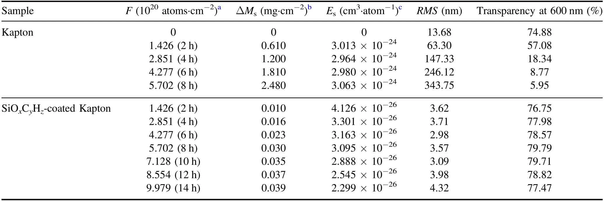
3.2.1.AO erosion kinetics.Figure 3 depicts the AO erosion kinetics of Kapton and SiOxCyHz-coated Kapton in the AO simulator from 0 to 9.979×10²⁰atoms·cm−2at different AO fluence.Under AO beam irradiation,the mass of Kapton samples degraded significantly.The mass of Kapton samples reduced approximately linearly under the impact of AO,as shown in figure 3 and table 2.When the irradiation time increased from 2 to 8 h,the erosion rate of the corresponding Kapton films remained around 3.0×10⁻²⁴cm3·atom−1,indicating that atomic oxygen could continuously erode the Kapton films.When the irradiation time exceeded 10 h,the Kapton was completely removed,as shown in the inset of figure 6(a).On the contrary,after deposition of the SiOxCyHzprotective coating,there was no substantial decrease in film mass,and the slight mass loss was related to the formation of volatile products during the exposure of the protective film to AO.When the irradiation time reached 14 h,the films remained intact,corresponding to an erosion rate of 2.299×10⁻²⁶cm3·atom−1,which is only 0.77% of that of the Kapton erosion rate.The results indicate that the SiOxCyHzcoating could effectively shield the Kapton film from AO erosion.In addition,we found that the erosion of the protective coating gradually decreased from 4.126×10⁻²⁶to 2.299×10⁻²⁶cm3·atom−1by increasing the AO irradiation time from 2 to 14 h.This indicates that the protective coating has a ‘self-reinforcing’ capability.

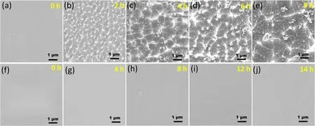
Figure 4.SEM images of pristine Kapton (a)-(e) and SiOxCyHz-coated Kapton (f)-(j) with different AO irradiation time.

Figure 5.Three-dimensional AFM images(5 μm×5 μm)of pristine Kapton(a)−(d)and SiOxCyHz-coated Kapton(f)−(i)with different AO irradiation time.Surface roughness spectrum of Kapton (e) and SiOxCyHz-coated Kapton (j) after exposure to AO.

Figure 6.Transmittance spectra of Kapton (a) and SiOxCyHz-coated Kapton (b) before and after exposure to a variety of AO fluence.The inset shows their optical photographs.

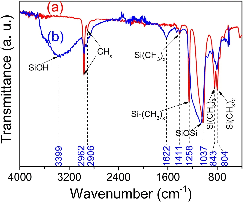
Figure 7.FTIR-ATR spectra of SiOxCyHz deposited on Al films before (a) and after (b) AO exposure with a dose of 1.28×10²² atoms·cm−2 (180 h).
3.2.2.Surface morphology and optical characteristics of Kapton and SiOxCyHz -coated Kapton after exposure to AO.To further study the effect of atomic oxygen on the microstructure of the substrate material and the protective film,the surface morphology of the pristine Kapton and SiOxCyHz-coated Kapton films before and after AO exposure was observed using SEM and AFM,as shown in figures 4 and 5,respectively.Before AO exposure,the Kapton surface was smooth with a pale-yellow transparent film,and the RMS value was 13.68 nm,as shown in figures S1,4(a) and 5(a).However,the surface morphology of Kapton films changed significantly with increasing AO irradiation time.From table 2,figures 4(b)-(e) and 5(b)-(e),the Kapton surface becomes coarser with increasing irradiation fluence,showing a ‘carpet-like’ topography,indicating that it suffers from serious atomic oxygen erosion.After AO irradiation,the original Kapton surface shows many short cones and wavy shapes,and the short cones gradually became larger due to molecular chain fragmentation,decomposition,and erosion of Kapton under AO irradiation,forming volatile compounds such as CO,CO2,NO,NO2and H2O.Meanwhile,the RMS value of the Kapton increases rapidly with the increase of AO exposure.The RMS value of the Kapton was increased from 13.68 to 343.75 nm at 0 to 8 h of AO exposure.Finally,the Kapton was eroded out after 10 h of AO exposure.In addition,the same conclusion could be drawn in the optical absorption spectrum,as shown in figure 6(a).Although the total thickness of the Kapton film decreased as the increase of AO fluence,which contributes to the reduction of light absorption,the optical transmittance of Kapton decreased significantly with the increase of AO fluence.The main reason for the transmittance change is that the surface
morphology of Kapton becomes coarser with increasing AO fluence,which resulted in the increase in reflectance (figure S3 in the supporting information).
In contrast,the surface color of SiOxCyHz-coated Kapton was almost the same as that of Kapton (figures 2(a) and S1),which was due to the excellent optical transmittance of the SiOxCyHzcoating at 350-2500 nm,as shown in figure 2(c).Compared with the pristine Kapton,the SiOxCyHz-coated Kapton was smoother,flatter,and denser,with an RMS value of only 3.26 nm,shown in figure 2(d).The results from the SEM and AFM plots of the SiOxCyHz-coated Kapton samples exposed to the atomic oxygen environment show that the surface morphology was almost unchanged,maintaining the original flat and dense surface morphology.Notably,no pinholes and micro-cracks were found on the surface of the SiOxCyHzcoating,which played an important role in the no serious loss of mass of the coating s during AO exposure,as shown in figures 4(f)-(g),and 5(f)-(i).The results showed that the SiOxCyHzcoating had a denser surface structure and excellent resistance to AO etching.In addition,the surface roughness of the coating decreases with increasing AO irradiation,probably because there is a selective reaction of AO with the topmost surface atoms (carbon,hydrogen,or silicon) of the SiOxCyHzcoating.Among these top surface atoms,the organic part of the SiOxCyHzcoating on the uppermost surface was etched and only silicon formed a nonvolatile oxide,and the gradual formation of a silicon-rich layer on the uppermost surface will retard further erosion.In addition,it can be seen in figure 6(b) that AO irradiation did not deteriorate the optical transmittance of the SiOxCyHzcoating as the AO irradiation dose increased.The results indicate that the SiOxCyHzcoating can be used in long-term AO irradiation conditions,keeping the optical properties of the substrate material stable.
3.2.3.Influence of AO on the chemical structure of the SiOxCyHzcoating.Furthermore,EDS and FT-IR measurements were also used to determine the component and chemical structure of the SiOxCyHzcoating.In figure S2 in the supporting information,the EDS results show that three elements,C,O,and Si,were found on the SiOxCyHzcoating.In the PECVD process,HMDSO and oxygen monomers were ionized in electron impact to form various molecular fragments such asetc [20].These fragments combined to form SiOxCyHzcoatings on the surface of Kapton.
Figure 7 shows the FT-IR spectra of the SiOxCyHzcoatings before (a) and after (b) AO exposure with a dose of 1.28×10²²atoms·cm−2(180 h).Table 3 summarizes the wave-numbers of the main absorption bands and their associated assignments (the values and assignments were taken from [20-22]).Figure 7(a) shows the FT-IR spectrum of the SiOxCyHzcoating deposited from a 30:50 HMDSO/O2plasma at P=400 W.One of the most prominent peaks at 1037 cm−1,located between 1000 and 1200 cm−1,was a doublet composed of the symmetrical and asymmetrical stretching modes of Si−O in Si−O−Si groups[15].Organic groups (methyl groups) were demonstrated to be present in the as-prepared SiOxCyHzcoating by the absorbance bands centered at 2962 cm−1(asym.ν C−H),2906 cm−1(sym.ν C−H),1411 cm−1,(δ C−H)1258 cm−1(ν C−H in Si(CH3)x),843 cm−1(δ C−H in Si(CH3)3) and 804 cm−1(δ C−H in Si(CH3)2) [23].However,after the SiOxCyHzcoating was irradiated with AO,a wide band of 3750-3200 cm−1,which was attributed to O−H stretching in silanol groups (Si−OH),was observed in the IR spectrum of the SiOxCyHzcoatings after exposure to an AO irradiation time of 180 h,as can be seen in figure 7(b).At the same time,the peak at 1037 cm−1(Si−O−Si) was shifted to a higher frequency at 1082 cm−1,and the intensity of the hydrocarbon absorbance bands at 2962 cm−1,2906 cm−1,1411 cm−1,1258 cm−1,843 cm−1,and 804 cm−1were either reduced or eliminated.This is attributed to the volatiles of water and carbon dioxide (CO,CO2) formed by the oxidation of the organic groups of the SiOxCyHzcoating and their subsequent removal from the coating.The reduction of carbon and hydrogen shows that the SiOxCyHzcoating was transformed into an inorganic SiO2-like coating with stronger resistance to atomic oxygen.

Table 1.Thermal radiation properties of Kapton and SiOxCyHz-coated Kapton.

Table 2.AO erosion data,optical transparency,and root mean square roughness (RMS) values for pristine Kapton and SiOxCyHz-coated Kapton before and after exposure to a variety of AO fluences.

Table 3.Wavenumber and assignments of the bands detected in the infrared spectrum of the SiOxCyHz films.

Table 4.Atomic concentrations and atomic ratios of the SiOxCyHz coating before and after AO exposure obtained from XPS data.

Figure 8.XPS spectra (a) and high-resolution Si2p XPS spectra of the SiOxCyHz coatings before (b) and after (c)-(e) AO irradiation.

Figure 9.Schematic diagram of the protective mechanism of SiOxCyHz coating upon AO irradiation.
X-ray photoelectron spectra (XPS) were used to determine the atomic concentrations (C,O,Si) and atomic ratios (O/Si) in SiOxCyHzcoatings before and after AO exposure (table 4).Before testing the XPS spectra of the samples,a 10 s Ar+pre-treatment was applied to clear the effect of the existence of carbon contamination on the surface of the samples.XPS spectra and an atomic concentration of the SiOxCyHzcoating before and after AO exposure are shown in figure 8 and table 4.Due to the reaction of carbon atoms at the surface region with AO to form volatile CO or CO2,the near-surface carbon concentration of the SiOxCyHzcoating decreased from 52.89% to 6.35% as the duration of atomic oxygen irradiation increased.During AO exposure,the oxygen concentration increased from 26.92% to 62.53%,and the atomic ratio of oxygen to silicon increased from 1.33 to 2.01,indicating that SiOxCyHzwas oxidized to SiO2.Figure 8 shows the high-resolution Si2pXPS of the SiOxCyHzcoating before and after AO exposure.Four different environments for silicon atoms were proposed[24],abbreviated as SiO(CH3)3,SiO2(CH3)2,SiO3(CH3),and SiO4with binding energies at 101.5,102.1,102.8,and 103.4 eV,respectively.Notice that SiO4represents a SiO2network.In figure 8,the intensity of SiO3(CH3) and SiO2(CH3)2components decreases,and the intensity of the SiO4component increases with the increase of the AO irradiation time.In other words,the center of the Si2ppeak shifts from 102.7 eV to a higher binding energy of 103.4 eV after AO exposure,corresponding to SiO2.This indicates the gradual formation of a thin SiO2film layer on the surface of the protective coating during the irradiation process.
The protection mechanism of the SiOxCyHzcoating upon AO irradiation is clearly illustrated in figure 9.When the SiOxCyHzcoating is exposed to the AO beam,the AO reacts with Si,C,and H on the surface of the coating,releasing volatile products such as CO,CO2,H2and H2O,and silicon oxide or silicon hydroxide remain on the coating surface.The presence of silicon dioxide effectively delays the reaction of AO with organic components,which is the main reason why the SiOxCyHzcoating materials are more resistant to AO attack than Kapton.In addition,during AO exposure,the coating becomes increasingly enriched in SiO2,forming a dense and complete silicon layer on its surface.This means that the resistance to AO of SiOxCyHzcoatings will further increase as the SiO2content increases,showing ‘self-enhancing’ behaviors.
4.Conclusions
An oxygen-resistant SiOxCyHzcoating with multiple properties such as flexibility,high optical transparency,denseness,homogeneity,and good adhesion was prepared on a large area of 1.2 m wide Kapton substrate using a roll-to-roll compatible PECVD process.The erosion kinetics,surface morphology,and surface composition of the pristine Kapton and SiOxCyHz-coated Kapton were investigated before and after AO exposure.The results show that the SiOxCyHzcoating has excellent oxidation resistance.Furthermore,an inorganic SiO2layer forms on the surface of the SiOxCyHzcoating during AO irradiation,which has a‘self-reinforcing’behavior and can effectively prevent AO from further eroding the underlying Kapton substrate.The prepared large-area SiOxCyHzfilms have great potential for the atomic oxygen protection of large-area organic materials on spacecraft traveling in LEO.The preparation process also provides a research foundation for the development of large-area flexible barrier films.
Acknowledgments
This work is financially supported by National Natural Science Foundation of China(No.U1937601),and the Industrial Technology Development Program of China (No.JCKY 2020203B019).
ORCID iDs
杂志排行
Plasma Science and Technology的其它文章
- Recent progress on the J-TEXT three-wave polarimeter-interferometer
- Design of the stripping unit and the electromagnetic analysis unit for the E//B NPA on HL-2A/2M tokamak
- Space-resolved vacuum-ultraviolet spectroscopy for measuring impurity emission from divertor region of EAST tokamak
- Development of a combined interferometer using millimeter wave solid state source and a far infrared laser on ENN’s XuanLong-50(EXL-50)
- Bench test of interferometer measurement for the Keda Reconnection eXperiment device (KRX)
- Neutron yield measurement system of HL-2A tokamak
