Understanding pitting corrosion behavior of AZ91 alloy and its MAO coating in 3.5% NaCl solution by cyclic potentiodynamic polarization
2022-07-13YuxingLiuZhuLiuAnyngXuXiotingLiu
Yuxing Liu, Zhu Liu, Anyng Xu, Xioting Liu
a National Key Laboratory for Remanufacturing of China, 21 Dujiakan, Fengtai District, Beijing 100072, China
b School of Materials, The University of Manchester, Manchester M13 9PL, UK
Abstract
Keywords: AZ91 alloy; MAO coating; Pitting corrosion behavior; Cyclic potentiodynamic polarization.
1.Introduction
Although characterized with lightweight, high strength to weight ratio, excellent damping capacity and favorable biological compatibility, magnesium (Mg) and its alloy exhibit poor corrosion resistance that hinders their development in applications including aerospace, automation, 3C industry(computer, communication and consumer electronic) and biomedicine [1–3].The use of different types of coatings is a promising approach for controlling corrosion for Mg alloys.Micro-arc oxidation (MAO, also referred to plasma electrolytic oxidation, PEO) coating has been widely prepared on the surface of Mg alloys with the aim of slowing down corrosion rate [4–7].Indeed, many results showed smaller corrosion rates and better corrosion resistance for the MAO-coated Mg alloys,though in most cases the experiments[4,5]were carried out in short-term immersion corrosion during which the MAO coating was still intact.
Unlike Al-based alloys that are susceptible to stable passivation [8–10], the passivity of Mg by forming an air-formed MgO film can be easily destroyed once the water molecule is present.Moreover, hydroxylation of the MgO film in aqueous solution results in the formation of a quasi-passive Mg(OH)2layer [3,11].Though the Mg(OH)2layer can grow in thickness, its thermodynamic instability in acidic and neutral solutions indicates a non-resistant film [12,13].Thus, the film and the layer experience pitting corrosion by their breakdown in aqueous solutions especially in the presence of chloride ions.In the absence of a stable passive film, pitting corrosion behavior of Mg alloys can be quite different from the alloys that have evident passivation and pitting potential on polarization curves.For example, Lamaka et al.[14]found acidification of solution inside the pits on Mg because of Mg2+hydrolysis just like the pitting corrosion of Fe-Cr alloys,leading to severe pitting corrosion of Mg substrate.However,Williams and McMurray [15–17]calculated the hydrolysis constant and claimed that acidification of solution inside the pits on Mg did not happen.They attributed the severe pitting propagation of Mg to the migration of Cl-.In addition to this, corrosion of Mg alloys is always characterized by fast anodic dissolution on anodic polarization curve that should have activation, passivation, pitting potential and transpassivation if pitting corrosion occurs.However, there are no such characterizations on anodic polarization curves for most Mg alloys though they are very sensitive to pitting corrosion.Song et al.[18]reported the pitting potential of pure Mg in 1M NaCl solution lied in cathodic polarization rather than in anodic polarization and was 15mV less noble with respect to corrosion potential.Thus, pitting corrosion behavior of Mg alloys can be quite tricky and it also definitely influences the corrosion morphology.Studies [19-23]illustrated an increasing area of dark regions deposited by an Mg(OH)2layer on Mg alloys under free corrosion and anodic polarization.This phenomenon was often used to elucidate the ‘negative difference effect’ on magnesium since the dark corrosion products are believed to enhance cathodic activity [15,21–23].The dark regions prior to the deposition of Mg(OH)2layer are actual locations where the breakdown occurs, subsequently pitting corrosion initiated and propagated to the width or depth.Similar to the MgO film, MAO coating can also offer passive corrosion protection for Mg alloys, if only it has good barrier properties [24].Unfortunately, the pores and cracks of MAO coating are natural pitting activation sites, probably leading to severe pitting corrosion once coating breakdown occurs.Due to the similarity, the investigation of pitting corrosion of the coating will contribute to the understanding of the pitting corrosion behavior of magnesium.
As we have mentioned above,the breakdown of the passive film (MgO film) or MAO coating leads to pitting corrosion,resulting in the formation of corrosion products of Mg(OH)2.In fact, corrosion products deposited on/in pits can in turn influence the initiation and propagation of pitting corrosion.Li et al.[25]found that pitting corrosion of AZ91D alloy spread to the depth leading to many deep corrosion pits while pitting corrosion of Mg-1.5Zn-0.6Zr alloy is more uniform and mainly spread to the width.They attributed to the corroded areas deposited with corrosion products which serve as cathodes promoting the dissolution of the non-corroded areas for the Mg-1.5Zn-0.6Zr alloy.Similarly, Li et al.[26]found that pitting corrosion propagated quickly on the MAO-coated AZ31 alloy after it initiated around micro-pores and cracks of the coating.Meanwhile, the corroded areas (pits) were deposited by corrosion products that were gradually peeled off as pitting corrosion proceeded.Such results are indicative of the association of pitting corrosion behavior of Mg alloys and MAO coating with not only pre-formed films but also corrosion products.
Among many approaches to study pitting corrosion of metals, cyclic potentiodynamic polarization technique (CPDP) is applicable as a method for prediction of pitting corrosion by providing the information of the beginning of passivity, the breakdown of an oxide film, susceptibility to repassivation and calculation of the rate of pitting corrosion due to the vast range of scanning potential [27,28].This technique has also been used for investigating the pitting corrosion of Mg alloys[25,27,29].Generally, no passivation behavior was observed during active dissolution for Mg and its alloys when anodic polarization of CPDP was conducted.Also, no repressivation potential occurs at the backward scan of CPDP and there is always a relatively large positive hysteresis loop which is present when the backward scanning curve is not overlaid with the forward one and the current density of backward scan is bigger than that of forward scan in the same potential.Thus, the consensus is that Mg and its alloys suffer from severe pitting corrosion.
Pitting corrosion of Mg alloys and MAO coating has been widely studied, mostly based on the microscale observations of pitting corrosion in various corrosion environments.In addition to the microstructural observations, it is also important to deeply examine pitting corrosion behavior by CPDP that can provide more information from the electrochemical viewpoint.In this paper, we investigated the pitting corrosion of AZ91 alloy and the MAO-coated alloy on it in 3.5% NaCl solution mainly by using the CPDP method, intending to provide an electrochemical explanation of pitting corrosion for the alloy and the coating.For this purpose, we first measured the general polarization and the 1st and 2nd cyclic potentiodynamic polarization.Next, we recorded the corroded surfaces at different polarization potentials by optical microscope and scanning electron microscope (SEM).Finally, we discussed the initiation and propagation of pits on AZ91 alloy and MAO-coated alloy based on the analysis of the CPDP results and the optical and SEM observations.
2.Material and methods
Commercial AZ91 Mg alloy (nominal compositions: 8.5–9.3 wt.% Al, 0.4–1.0 wt.% Zn, 0.15 wt.% Mn and balance Mg) was used as the substrate material.The MAO coating was prepared using a home-made micro-oxidation device (JHMAO-1000) equipped with a pulsed power supply(the maximum output is 1000V/5 A).The electrolyte for MAO treatment was prepared by dissolving reagent grade sodium phosphate (10.5g/L) and potassium hydroxide (1g/L)in deionized water.The pH of the electrolyte was 12.76.The temperature of the electrolyte was kept at 15–20°C using a water-cooling facility during the MAO process.A stainless steel (type 304) barrel (φ20mm×25mm) was used as the electrolyte container and cathodic electrode at the same time.The total treatment duration lasts 15min with a constant voltage of 500V, a frequency of 400Hz and a duty cycle of 30%.Prior to carrying out the MAO treatment and electrochemical measurements, AZ91 alloy specimens (10×10×5mm) were ground by using silicon carbide (SiC) emery papers up to 1200 grit (the surface roughness of the substrate and the prepared MAO coating was measured by using a laser confocal scanning microscope (Olympus OLS4000), and the value is2.055±0.527μm and 3.720±0.260μm, respectively.Noting that the measured area of the surface is 0.1 mm2for both the alloy and the coating), then ultrasonically degreased in acetone, washed in deionized water and dried in cold air, respectively.
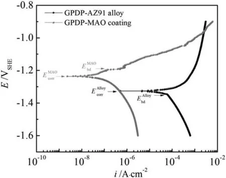
Fig.1.General potentiodynamic polarization (GPDP) curves for AZ91 alloy and MAO coating in 3.5% NaCl solution.
Electrochemical measurements were carried out using a ZAHNER-ENNIUM electrochemical workstation in 3.5%NaCl solution at room temperature.A three-electrode cell configuration consisting of a working electrode (AZ91 alloy or MAO coating), a Pt counter electrode and a saturated calomel electrode (SCE) were used.The exposed surface area of working electrodes was 1 cm2.The open circuit potential (OCP) of the alloy and the coating was recorded for 0.5h.Cyclic potentiodynamic polarization was conducted after OCP, at a scan rate of 1mV/s in the range from -500mV to 550mV vs.OCP.
The optical surface morphology at different polarization potentials were recorded on the same sample (one AZ91 alloy sample and one MAO-coated alloy sample) using a USB digital microscope (Mixout, W04-Wi-Fi Digital Microscope,IvyJane, China).After each scans of the 1st and 2nd CPDP,the surface and cross-sectional corrosion morphology were characterized by a scanning electron microscopy(Quanta 200,FEG, FEI) equipped with energy dispersive X-ray (EDS) analyzer.The compositions of the corrosion products formed during CPDP measurements were identified by using the EDS analyzer and a Fourier Transform Infrared spectrometry(JASCO FTIR-4200 series spectrophotometer) between 4000 and 400 cm-1and a resolution of 4 cm-1.
3.Results and discussion
3.1.General potentiodynamic polarization (GPDP)
Fig.1 shows the general potentiodynamic polarization curves of AZ91 alloy and MAO coating.From Fig.1, we can decide that AZ91 alloy has a corrosion current density(icorr)of 3 orders of magnitude bigger than MAO coating does though its corrosion potentialEcorr(-1.327V vs.SHE) approximates theEcorr(-1.237V vs.SHE) of the coating.The smaller corrosion current density on MAO coating can be due to that the coating serves as a barrier against the corrosion.By comparison, the air-formed MgO film on AZ91 alloy is thin and ready to dissolve in aqueous solution and transforms into the quasi-passive hydroxide film that is very unstable at acidic and neutral solutions [30], leading to a fast corrosion rate.We can also see that the breakdown potential(Ebd)exists on GPDP curves for both AZ91 alloy and MAO coating.It is interesting thatEbdfor AZ91 alloy is 20mV more negative than itsEcorrwhereas it is opposite for MAO coating.AtEbd,the current density on both the alloy and the coating changes greatly, indicating that film/coating breakdown occurs.Noting that the current density of MAO coating soars afterEbd,which can be attributed to the severe pitting corrosion after coating breakdown.Moreover, galvanic corrosion may also contribute to the dramatic increase of current densities because of the less nobleEcorrof the underlying substrate (AZ91 alloy) with respect toEcorrof the coating.Finally,an intersection emerges atE=-0.961V vs.SHE on GPDP curves indicating that a small anodic polarization on MAO coating after its breakdown leads to a bigger anodic reaction rate with AZ91 alloy as a comparison.Overall, the critical pitting corrosion is the major corrosion form for both AZ91 alloy and MAO coating.
To further elucidate the pitting corrosion behavior of the alloy and the coating,we decomposed the GPDP curves(Fig.1)into actual Tafel lines which originates from individual redox reactions that occur at the same time on different regions of the electrodes,as shown in Figs.2 and 3.Noting that the activation controlled kinetics are assumed in the analyses.For redox reactions that occur on different surfaces, kinetic parameters including exchange current densities and Tafel slopes are different.Naturally,hydrogen evolution exchange current density on AZ91 alloy is smaller than that on both MgO film and MAO coating and Mg dissolution exchange current density on different surfaces is assumed constant [19,31].Also, anodic Tafel slope (positive) is bigger on film/coating with respect to AZ91 alloy while cathodic Tafel slope (negative) is smaller on film/coating [32,33].Accordingly, the exchange current density and Tafel slope experience a significant change when the MgO film or the MAO coating ruptures and the underlying alloy substrate exposes to the solution.Under such facts and assumptions, the hypothetical Tafel lines in Fig.2 and Fig.3 show the kinetics associated with Mg oxidation reaction and hydrogen evolution reaction on different surfaces.
From Figs.2 to 3,we can see that atEbdwhere the surface nature changes, the anodic and cathodic Tafel lines deflect according to the changes of the exchange current density and the Tafel slope.Specifically, the cathodic Tafel line is initially controlled by theic,H,MgOoric,H,MAObeforeEbdand after which it is controlled byic,H,Mg.Similarly, beforeEbdthe anodic Tafel line is mainly decided byia,MgOoria,MAOand afterEbd, it is decided byia,Mg.Noting that there is a dashedline betweenia,MgOoria,MAOandia,Mg, indicating that current density experiences a sudden increase after the breakdown of the film/coating.
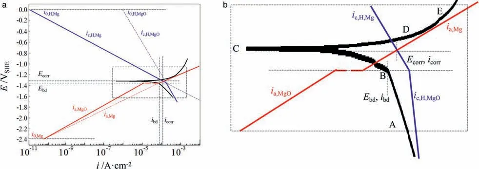
Fig.2.Schematic Evan’s diagram explaining the GPDP curve for AZ91 alloy (Fig.1) by decomposing it into Tafel lines based on the differences of kinetic parameters of redox reactions that occur on surfaces of the air-formed MgO film and AZ91 alloy substrate (a) and (b) the magnified views of the rectangular regions in (a).The letters from A to E in (b) represent the selected points that are essential on the GPDP curve.
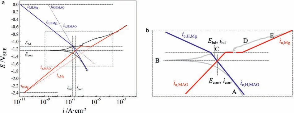
Fig.3.Schematic Evan’s diagram explaining the GPDP curve for MAO coating by decomposing it into Tafel lines based on the differences of kinetic parameters of redox reactions that occur on surfaces of the MAO coating and AZ91 alloy substrate (a) and (b) the magnified views of the rectangular regions in (a).The letters from A to E in (b) represent the selected points that are essential on the GPDP curve.
Figs.2b and 3b show the magnified views of the rectangular regions in Figs.2a and 3a where the Tafel lines deflect.The experimental GPDP curves are also illustrated to verify whether the hypothetical Tafel lines are well-plotted.Since the evolution of corroded surfaces of the substrate and the film/coating during polarization is responsible for shaping the GPDP curves, it is necessary to illustrate the evolution by recording the corroded surfaces at certain important polarization potentials.BesidesEbd, we pick up another 4 points labeled as from A to E as shown in Figs.2b and 3b.Figs.4 and 5 show the optical images of the corroded surfaces at these points along with their potentials and current densities for AZ91 alloy and MAO coating,respectively.The potentials and current densities of each selected point are also listed in Table 1.

Table 1Potential and current density of the selected points in Figs.2b and 3b.
At point A which is in the cathodic branch in Fig.4,the surface of AZ91 alloy is covered with the MgO film,thus rapid hydrogen evolution occurs on the alloy electrode but anodic dissolution is depressed.Point B represents that the MgO film ruptures and pits initiate.Before point B, because hydrogen evolution occurs on MgO film, the cathodic branch is dominated byic,H,MgO-ia,MgO, resulting in a smallercathodic Tafel slope (negative), as shown in Fig.2b.At point B, pits start to initiating on AZ91 alloy surface, as shown in Fig.4 the arrows (in blue) on the image labeled with B.The initiation of pits at point B leads to the exposure of fresh AZ91 alloy substrate where the redox reactions have different Tafel slopes and hydrogen evolution exchange current density as on MgO film, resulting in a bigger change of current density even when a smaller polarization potential is applied from B to C.Point C isEcorrwhere anodic current density equals to cathodic current density.However, since anodic dissolution is still depressed from B to C, Mg dissolution reaction in the existing pits is negligible and no propagation takes place.It should be noted that atEcorra new pit appears (the red arrow on image C) due to the sufficient energy provided by the Mg oxidation overpotential which is high enough to trigger more film to rupture.Overall, in the cathodic branch, the alloy surface has no big changes in appearance.
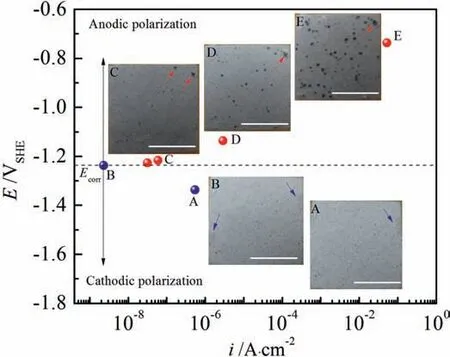
Fig.5.Potentials and current densities of the selected points (from A to E in Fig.3b) and the inserts are optical observations of corroded surfaces of MAO coating at these points (also labeled from A to E for convenience), the scale bars=5mm.
However, by lifting potential about 100mV aboveEcorrto point D, a significant increase of current density (Fig.2) and a dramatic change of corrosion appearance occurs (Fig.4 the image D),showing a certain amount of pits initiates randomly on the corroded surface but only propagates slightly.Such pitting corrosion behavior can be explained as follows.AfterEcorr, the increasing anodic polarization potential triggers more and more pits due to the considerable overpotential of the Mg oxidation reaction.At the same time, anodic potential requires electrons flowing out from the alloy electrode to the potentiostat.The requirement can be fulfilled more easily by Mg dissolution inside the new-formed pits because the undamaged MgO film is resistant to losing electrons when the anodic potential is not such big.Unfortunately, the MgO film readily dissolves and it ruptures as anodic polarization potential rises.Thus, instead of propagating to the depth leading to deep corrosion pits, the pitting corrosion spread to the width to attack the undamaged MgO film.Moreover, according to the literature [19–23], the horizontally expanding pits are actually covered with corrosion products of Mg(OH)2.They deposit on the shallow pits upon which further magnesium dissolution reaction is difficult to take place under the condition of a quite high local pH, leading to a high mechanical bonding strength between the layer of corrosion products and AZ91 alloy substrate.Eventually, with shallow pits spreading,the corrosion products layer takes over the entire alloy surface and might serve as a protective barrier.Such phenomenon can be observed in image E in Fig.4 that at point E where the applied anodic potential is noble enough a large area of AZ91 alloy surface is covered by the Mg(OH)2layer.An interesting phenomenon in Fig.4 is that no pitting propagation happens on the pits that develop at point B (blue arrows in image B)but a slight propagation occurs on the pits that form atEcorr(red arrow in image C).This can be due to that the pits atEcorrare still very reactive but the pits at point B are more susceptible to repassivation which will be discussed in cyclic potentiodynamic polarization parts.
As a comparison, pitting corrosion behavior of MAO coating is quite different from that of AZ91 alloy, as shown in Fig.5.Normally, the MAO coating is about 20–50μm in thickness [4,5,24]and it is an excellent physical barrier to inhibit corrosion before its electrochemical breakdown.Thus,a big overpotential of Mg oxidation is required to rupture the coating, resulting in the absence of pitting corrosion atEcorrthough a large number of pores that are ready to trigger localized corrosion exist in/on the coating.Besides, the Mg dissolution reaction is depressed from A to B under cathodic polarization potential.This is the reason why pitting corrosion scarcely happens from point A to point B in Fig.5.The very slow anodic reaction rate from A to B keeps MAO coating appearance, as shown in image A and image B in Fig.5, but still the chemical dissolution of the coating (magnesium oxide and phosphate) occurs resulting in certain graymarks(the blue arrows in Fig.5).In addition to the depressed anodic reaction, the cathodic reaction of hydrogen evolution also proceeds slowly(current density at both point A and B is very small), proving that the cathodic Tafel slope (negative)is small for hydrogen evolution reaction on MAO coating(Fig.3) with respect to AZ91 alloy substrate.
When anodic polarization potential is applied,Ebd(point C) emerges followingEcorr,and the current density at this potential experiences a rapid increase.This can be attributed to the initiation of pits at the micro-pores and cracks on MAO coating (the red arrows in Fig.5 on image C).Some blind pores also contribute to pits initiation after their exposure to the NaCl solution because of the chemical dissolution of the coating above them.The exposed alloy substrate beneath the new-formed pits has a very small anodic Tafel slope, as a result, anodic current density soars even a small anodic polarization potential is applied.When a big anodic polarization potential is applied, for example at point D, the corresponding current density requires a great amount of electrons that come from Mg oxidation reaction.For MAO coating, we can conclude from image C and image E in Fig.5 that these electrons come from the dissolution of the underlying Mg metal in the local pits that propagate to the depth (the red arrows).This is because the undamaged MAO coating is quite resistant to corrosion leading to more difficulty in pits spreading to the width.Thus, at point E there are a big number of localized pits that penetrate the MAO-coated alloy deeply,which is responsible for the considerably big current density at the end of anodic polarization in Fig.1.Moreover, because of the severe Mg oxidation reaction and the acidification of the solution inside the pits (in addition to rapid migration of Cl-), corrosion products on MAO coating cannot form a dense layer, and they are not as protective as the Mg(OH)2layer deposited on AZ91 alloy.
3.2.1st cyclic potentiodynamic polarization (1st CPDP)
With the aim of further investigating the pitting corrosion propagation on AZ91 alloy and MAO coating, the 1st CPDP curves in Fig.6 are provided.From Fig.6, we can confirm that the pitting corrosion behavior of AZ91 alloy and MAO coating is quite different by observing the shapes of the 1st CPDP curves.To start with, we are going to discuss the conspicuous characteristics of the curves.Both AZ91 alloy and MAO coating have a positive hysteresis loop that is indicative of the difficulty in stopping the growth of pits, i.e.the same change of current density needs a bigger change of polarization potential for the backward scan with respect to the forward scan.Thus,once pits initiate on corroding surfaces,it is hard for them to stop propagating since the backward scan has a slow decrease of current density.Moreover, the size of the hysteresis loop can be decided by the difference between the forward and backward current density.Practically,a bigger size of positive hysteresis indicates more difficulty in restoring the damaged film/coating.From Fig.6, we can see that the size of the positive hysteresis loop is bigger for MAO coating, indicating that MAO coating is more susceptible to pitting corrosion and the damaged coating are more difficult to restore at noble potentials.The difficulty could be due to that the pits on MAO coating propagate to the depth and the corresponding corrosion products are not susceptible to repassivation (Fig.5).By comparison, pits on AZ91 alloy spread to the width and they are more susceptible to repassivation by the corrosion products (Fig.4).As the evidence,the intersection of the forward scan and backward scan of the 1st CPDP for AZ91 alloy at -1.4V vs.SHE can be the repassivation potential.
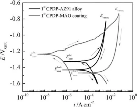
Fig.6.Typical cyclic potentiodynamic polarization (CPDP) curves for AZ91 alloy and MAO coating in 3.5% NaCl solution.
Fig.6 also shows that the corrosion potential of the forward scan (Efor.corr) is more noble than the corrosion potential of the backward scan (Eback.corr, also referred to anodic to cathodic transition potential).Generally speaking, if a metal is very susceptible to repassivation,the passive film on the metal will be resistant ifEfor.corris nobler thanEback.corr[27].Unfortunately, there is no stable passive film existing on both AZ91 alloy and MAO coating, thus the conflict stands out if we conclude that pits are going to be repassivation at the backward scan and the damaged film will restore based on the less nobleEback.corrin Fig.6.An alternative way to explain the more negativeEback.corris that the potential of the corroded areas (Eback.corr) is more negative than the uncorroded area (Efor.corr), leading to the corroded areas serving as anodic regions and continuing to corrode.Accordingly, the pits at the corroded areas will propagate to the depth, which is inconsistent with the actual pitting growth behavior for AZ91 alloy in Fig.4 but agrees well with the behavior of pitting corrosion for MAO coating in Fig.5.
With the aim of elucidating whetherEback.corrcan represent corrosion potential of the corroded areas, open circuit potential (OCP) before and after GPDP for AZ91 alloy and MAO coating in Fig.7 is provided.Fig.7 shows that before GPDP the OCP for both AZ91 alloy and MAO coating is consistent withEcorrin Fig.1.Also, the OCP for MAO coating after GPDP has a good agreement withEback.corrinFig.6.The agreement ofEcorrwith OCP for MAO coating in Figs.1, 6 and 7 substantiates the above analysis that pits on MAO coating propagate to the depth.However, it is a different story for AZ91 alloy.The OCP of AZ91 alloy after CPDP is more noble in Fig.7 than the OCP before CPDP,which contradicts the relative values ofEfor.corrvs.Eback.corrin Fig.6.Correspondingly, we can confirm thatEback.corrcannot represent the corrosion potential of the corroded areas for AZ91 alloy.In fact, based on the images in Fig.4 and OCP curves in Fig.7, we can conclude that pits on AZ91 alloy spread to the width.
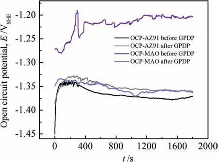
Fig.7.Open circuit potential curves for AZ91 alloy and MAO coating in 3.5% NaCl solution before and after general potentiodynamic polarization.
Furthermore,the critical pitting corrosion can also be characterized by the potential difference betweenEfor.corrandEback.corrin Fig.6 and OCP difference in Fig.7.The larger the difference, the severer the galvanic corrosion between film/coating and the exposed AZ91 alloy substrate beneath the pits.Figs.6 and 7 show a bigger difference betweenEfor.corr(or OCP before GPDP) andEback.corr(or OCP after GPDP)of MAO coating, indicating that pits propagating to the depth dictate the behavior of pitting corrosion for MAO coating.As for AZ91 alloy, its pitting corrosion behavior is more likely controlled by pits spreading to the width because the galvanic corrosion of the exposed AZ91 alloy substrate beneath the pits is moderate.In summary, we can conclude that pits on AZ91 alloy spread to the width whereas pits propagate to the depth on MAO-coated alloy.
As the corroded surface is optically observed at certain special points on GPDP curves in Figs.4 and 5, so is the corroded surface at some points (from F to J) of backward scan of the 1st CPDP in Fig.8 and Fig.9 for both AZ91 alloy and MAO coating.The corresponding potentials and current densities of the point are listed in Table 2.
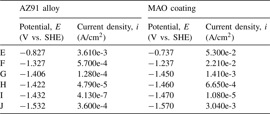
Table 2Potentials and current densities of the selected points in Figs.8 and 9.
In Fig.8a, we can see that corrosion current density(iback.corr) of the backward scan approximatesifor.corrof the forward scan for AZ91 alloy.Moreover, at point E (Evertexin Fig.6) and point J the backward scanning curve superposes the forward scanning curve at a relatively big region of polarization potentials.The similarity of corrosion current density and the overlap of scanning curves implies that thelayer of corrosion products deposited in the corroded areas after GPDP has an approximate corrosion resistance as the MgO film does.In addition, the layer is not susceptible to pitting corrosion and is capable of promoting repassivation of pits on AZ91 alloy (the potential at point G might be the repassivation potential).
Fig.8b shows corroded surface appearances at different points along the backward scanning curve.AfterEvertex(point E), the applied anodic polarization potential drives electrons from electrode to the potentiostat, leading to Mg dissolution at points F, G and H although at a decreasing reaction rate from E to H.During the backward scan, because the corroded areas are covered with the protective layer of corrosion products, it is difficult for the corroded areas to offer electrons by the further dissolution of the underlying AZ91 substrate.Therefore, it is reasonable that pitting corrosion will continuously propagate to the uncorroded areas (undamaged MgO film), leading to an increasing corroded area.This interpretation can be verified by the changes of surface appearances from image E to image F-G-H in Fig.8b that certain uncorroded areas are covered with new-formed corrosion products highlighted by a yellow elliptical frame.With the potential reduction toward more negative potentials to point I (Eback.corr)and J, anodic dissolution of Mg metal is depressed by cathodic polarization potential, resulting in unchanged surface appearances in the image I and image J.
Fig.9a shows a significant increase in the current density of the backward scanning curve for the MAO coating.It is conceivable that more noble potentials applied on MAO coating (such as point E) produce great damages to the coating structure, resulting in a very big current density on backward scan even a decade bigger than the current density of AZ91 alloy in the same backward potentials (Fig.6).Eventually,the corrosion current density of backward scan rises about 4 orders of magnitude compared with the forward scan.Such a big corrosion current density of backward scan signifies that the pits that propagate to the depth have consumed a large area of AZ91 alloy substrate beneath the coating which cannot offer corrosion protection any longer.Moreover, the corrosion products formed in the pits are also vulnerable to the localized acid solution and Cl-and are not so resistant as the corrosion products on the AZ91 alloy.Eventually, corrosion of MAO coating during the backward scan is likely to take place on the AZ91 alloy substrate without any film orlayer, which can be responsible for the considerable corrosion current density of backward scan in Fig.9a.Moreover,there is no repassivation potential on the backward scanning curve indicating the damage of MAO coating produced by the existed and new-formed pits is difficult to restore.
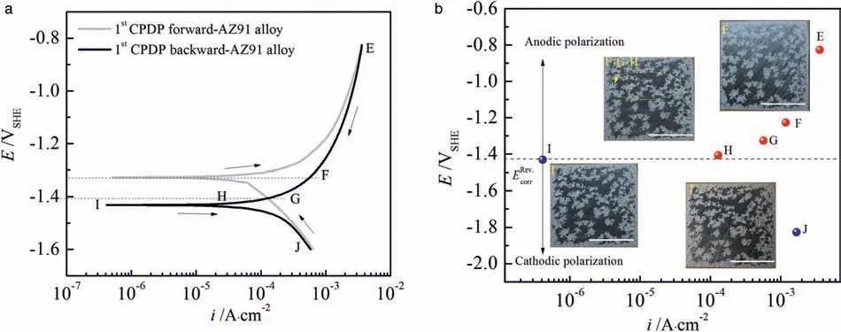
Fig.8.Typical cyclic potentiodynamic polarization curves for AZ91 alloy in 3.5% NaCl solution (a); the letters from E to J represent the selected points that are essential on the CPDP curve and (b) the potentials and current densities of the selected points on the backward scanning curve; the inserts are optical observations of corroded surfaces of the AZ91 alloy at these points (also labeled from E to J for convenience), the scale bars=5mm.

Fig.9.Typical cyclic potentiodynamic polarization curves for MAO coating in 3.5% NaCl solution (a); the letters from E to J represent the selected points that are essential on the CPDP curve and (b) the potentials and current densities of the selected points on the backward scanning curve; the inserts are optical observations of corroded surfaces of MAO coating at these points (also labeled from E to J for convenience), the scale bars=5mm.
The optical observations of the corroded surface in Fig.9b show that more and more pits initiate (image F) and the existed ones spread to big areas (image G-H) with respect to image E along the anodic branch of the backward scan.When the cathodic branch is reached,the surface appearances do not change much (image I and J) only showing evident pitting corrosion morphology.Though MAO coating is still covering AZ91 alloy substrate after the 1st CPDP, we can conclude that MAO coating has lost its function as a barrier to protect the substrate.
3.3.2nd cyclic potentiodynamic polarization (2nd CPDP)
To further investigate what will happen to the pitting corrosion on the corroded surfaces of AZ91 alloy and MAO coating after the 1st CPDP, we apply the 2nd CPDP along with the 1st CPDP that are shown in Fig.10.From Fig.10, we can observe that the 2nd CPDP curve of AZ91 alloy almost overlays the 1st CPDP curve, except that a small nobleEcorrand a small increase positive hysteresis loop occur.The very similar CPDP curves imply that corrosion behavior of the air-formed MgO film and the layer of corrosion products after 1st CPDP is almost identical with the very similar corrosion current density and hydrogen evolution kinetic characteristics.However,the small nobleEcorrat 2nd CPDP indicates that the hydrogen evolution exchange current density on corrosion products(Mg(OH)2) is a bit bigger than that on MgO film.Moreover,the slightly bigger positive hysteresis of the 2nd CPDP meansthat the layer of corrosion products are more susceptible to pitting corrosion with respect to the MgO film.
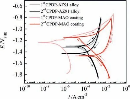
Fig.10.The 1st and 2nd cyclic potentiodynamic polarization curves for AZ91 alloy and MAO coating in 3.5% NaCl solution.
For MAO coating, a significant difference occurs on forward scans between the 1st and 2nd CPDP whereas the backward scans are almost overlaid, as shown in Fig.10.Compared with the forward scan of the 1st CPDP, corrosion potential becomes more noble and corrosion current density increases 3 orders of magnitude reaching the same value as AZ91 alloy has.The dramatic increase of current density is mainly due to the significant move of the cathodic branch to the high current density direction because the anodic branch of the forward scan of the 2nd CPDP follows that of the 1st CPDP.The cathodic reaction becomes active on the corroded MAO coating probably because of the enhancement of hydrogen evolution activity by corrosion products of Mg(OH)2.The backward scan of the 2nd CPDP superposes the backward scan of the 1st CPDP, indicating a similar surface appearance and pitting corrosion behavior presents at backward scans.Moreover, the size of the positive hysteresis loop becomes smaller, which can be attributed to the increase of current density on the forward scan of the 2nd CPDP but pitting corrosion proceeds the same way as the 1st CPDP in Fig.9.
When compared with the 2nd CPDP of AZ91 alloy, the corrosion potential of the 2nd CPDP of MAO coating is more noble but corrosion current density is approximate.This similarity is indicative of a comparable corrosion rate on the corroded surface for both AZ91 alloy and MAO coating after the 1st CPDP.However, the anodic reaction rate is far faster for MAO coating than AZ91 alloy during the 2nd CPDP, implying that pitting corrosion under the residual MAO coating leads to more damage.As a result,the corroded MAO coating will produce a considerable amount of electrons by the dissolution of the underlying alloy substrate even when a small anodic polarization potential is applied.Moreover, the bigger size of positive hysteresis of MAO coating over AZ91 alloy during the 2nd CPDP indicates the more difficulty in stopping pits growth under the residual MAO coating.
3.4.Corrosion morphology and corrosion products
Figs.11 and 12 illustrate the evolution of pitting corrosion for AZ91 alloy and MAO coating after 1st and 2nd CPDP.In Fig.11 for AZ91 alloy,an increasing area of corroded surface covered by corrosion products is observed when the 1st CPDP(a.1 the forward scan and b.1 the backward scan) and the 2nd CPDP (c.1 the forward scan and d.1 the backward scan)were conducted, which is consistent with the observations in optical images and the analyses of CPDP.At backward scan of 2nd CPDP (d.1), the corrosion products almost take over the entire alloy surface.By comparison, the corroded surface of MAO coating is characterized by individual pits that grow in number and size when the 1st CPDP and then the 2nd CPDP were conducted.However, the pits on MAO coating propagate locally and deeply, developing a morphology that corrosion products inside the deep pits only partially takes over the coating surface, as can be seen in Figs.11d.1 and 11d.2.Fig.12 shows the cross-sectional SEM images of the polarized alloy and coating (the coating’s thickness is about 30μm).From Fig.12, we can see that pits on AZ91 alloy are shallow and develop horizontally whereas they propagate deeply on MAO coating.The surface and cross-sectional SEM images in Figs.11 and 12 validate the analyses of 1st and 2nd CPDP that pits spread to the width on AZ91 alloy while they propagate to the depth on MAO-coated alloy.
Fig.13 shows the magnified surface and cross-sectional SEM images in Figs.11d.1, d.2 and 12d.1, d.2.From Fig.13,we can observe that the corroded surface of AZ91 alloy(Fig.13a,c) are covered by a layer of corrosion products that are quite dense and develop a strong bonding strength with the alloy substrate.This protective layer decides the CPDP behavior of AZ91 alloy in Fig.10 and influence the pitting corrosion behavior that pits spread horizontally.For MAOcoated alloy (Fig.13b,d), we can observe that the corrosion products in the deep pits are only some debris that cannot serve as a barrier so protective as the corrosion products layer on AZ91 alloy.Moreover, the MAO coating around the pits is beginning to flake off, as shown in Fig.13d the white arrow.As a result, such residual MAO coating seems to lose its function as a barrier and cannot offer corrosion protection any longer.Overall, the corrosion products debris and the residual MAO coating make it easy for the pits to propagate to the depth to consume the AZ91 alloy substrate beneath the coating, leading to considerable corrosion current density of backward scan in Fig.9a and more difficulty in stopping pits growth.
The compositions of the corrosion products formed on AZ91 alloy and MAO coating after 2nd CPDP were identified by EDS and FTIR spectra and the results are depicted in Figs.14 and 15.In Fig.14 the EDS elemental mapping results show that the elements that constitute the corrosion products on AZ91 alloy and MAO coating are identical.The corrosion products are in rich in Mg and O and a small amount of C and Al for both the alloy and the coating.It is interesting to note that phosphorus only exists on the undamaged MAO coating in Fig.14(b) and it disappears at thetop of the pits, indicating that pits totally consume the MAO coating when they propagate to the depth.Fig.15 shows the FTIR spectra of the corrosion products on the AZ91 alloy and MAO coating before and after CPDP.For AZ91 alloy, we can observe the existence of vibrations bands around 672 cm-1which are characteristics of Mg-O covalent band.After coated with MAO coating and 2nd CPDP, oxide, hydroxide, carbonate and phosphate formed on these surfaces.For AZ91 alloy and MAO coating after 2nd CPDP, the broad band between 3000 cm-1and 3500 cm-1and the peak at 1635 cm-1are related to the hydroxide group which indicates the formation of Mg(OH)2.Moreover, the MgO peaks at 867 cm-1appear on the corroded surfaces indicating the coexistence of MgO and Mg(OH)2in corrosion products.The carbonate ions (CO32-)also exists on the alloy and coating after 2nd CPDP resulting from the exchange of CO2between air and oxide/hydroxide.Based on the above EDS results and FTIR spectra, the corrosion products are considered as Mg(OH)2and a small amount of magnesium oxide and carbonate.
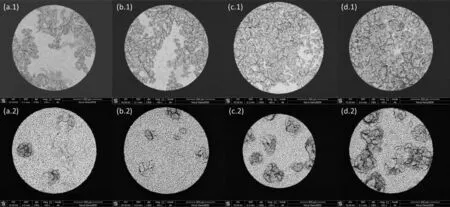
Fig.11.SEM images of representative corroded surfaces at different potentials along 1st and 2nd CPDP for AZ91 alloy and MAO coating: (a.1-d.1) is for AZ91 alloy and (a.2-d.2) is for MAO coating; a.1 and a.2 is for 500mV vs. Efor.corr at 1st CPDP forward scan, b.1 and b.2 is for 10mV vs. Eback.corr at 1st CPDP backward scan, c.1 and c.2 is for 500mV vs. Efor.corr at 2nd CPDP forward scan, d.1 and d.2 is for 10mV vs. Eback.corr at 2nd CPDP backward scan.
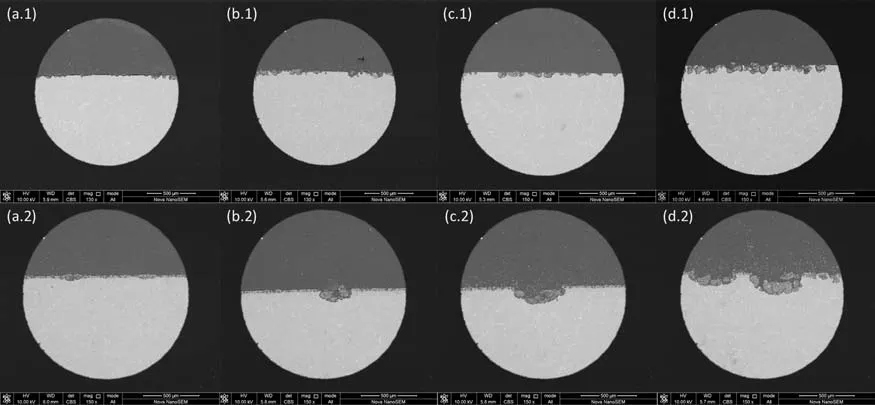
Fig.12.SEM cross-sectional images of AZ91 alloy and MAO coating after polarization at different potentials along 1st and 2nd CPDP: (a.1-d.1) is for AZ91 alloy and (a.2-d.2) is for MAO coating; a.1 and a.2 is for 500mV vs. Efor.corr at 1st CPDP forward scan, b.1 and b.2 is for 10mV vs. Eback.corr at 1st CPDP backward scan, c.1 and c.2 is for 500mV vs. Efor.corr at 2nd CPDP forward scan, d.1 and d.2 is for 10mV vs. Eback.corr at 2nd CPDP backward scan.
In summary, pitting corrosion propagates differently on AZ91 alloy and MAO-coated alloy during CPDP though the compositions of the corrosion products inside the pits are identical.The corrosion products on AZ91 alloy develops a relatively dense and protective layer, which is responsible for pits spreading to the width.Moreover,the protective layer and the horizontally developed pits are the reason for the similarity of the 1st and the 2nd CPDP for AZ91 alloy.By comparison, the MAO coating is protective before its breakdown.However, due to the existence of the pores and cracks on the coating surface, it is natural that pits initiate locally on theselocations and propagate to the depth.Moreover, the corrosion products inside the pits on MAO-coated alloy are incapable of stop pitting propagating deeply, resulting in a very different pitting corrosion behavior at 1st CPDP and 2nd CPDP.Overall, the results in this paper show that the MAO coating without post-treatments may promote the corrosion rate of AZ91 alloy and suffer from severe pitting corrosion, which is consistent with conclusions in references[7,26,34–37].Therefore, it is necessary to raise the breakdown potential of MAO coating,so that the MAO-coated AZ91 alloy can endure longterm immersion corrosion and galvanic corrosion.
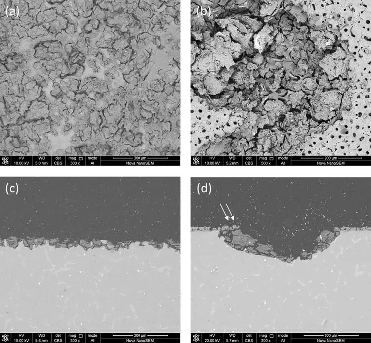
Fig.13.Surface and cross-sectional SEM images of AZ91 alloy and MAO coating after 2nd CPDP (d.1 and d.2 in Fig.11 and Fig.12): (a) and (c) are for AZ91 alloy, (b) and (d) are for MAO coating.
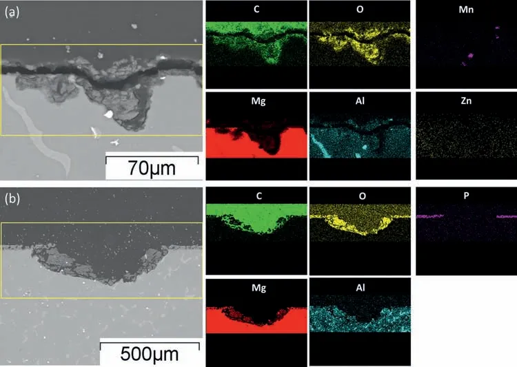
Fig.14.EDS elemental mappings of corrosion products formed on AZ91 alloy (a) and MAO coating (b) after 2nd CPDP.
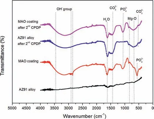
Fig.15.FTIR spectra of the AZ91 alloy and MAO coating before CPDP and after 2nd CPDP.
Conclusions
The pitting corrosion behavior of AZ91 alloy and MAOcoated alloy in 3.5% NaCl solution was investigated by cyclic potentiodynamic polarization with the aim of elucidating how pits initiate and propagate.It was found that the breakdown potential on GPDP curve for AZ91 is about 20mV more negative thanEcorrwhereas it is 20mV more positive thanEcorrfor MAO-coated alloy.Such difference can be attributed to the differences of kinetic parameters (Tafel slope and hydrogen evolution exchange current density) between the air-formed MgO film on AZ91 alloy and MAO coating.As a result,the hypothetical Tafel lines deflect atEbd, further giving rise to very different polarization curves.Analysis performed on CPDP curves indicates a different pitting corrosion behavior for the alloy and the coating.Specifically, pits on AZ91 alloy spread to the width whereas pits propagate to the depth on MAO-coated alloy.Such behavior was proved by the optical and SEM images of corroded surfaces at different potentials along CPDP curves.For AZ91 alloy, pits spreading to the width is due to the layer of corrosion products formed during 1st CPDP in the corroded areas.The layer is so resistant to corrosion that it is difficult for pits growth under it and it can endure the 2nd CPDP without an evident increase of corrosion rate.By comparison, the pores on MAO coating are natural activation areas for pitting corrosion, leading to deep pits under the coating after its breakdown.In addition, corrosion products inside the pits are not so protective as the layer on AZ91 alloy, resulting in a more severe pitting corrosion of MAO coating during the 2nd CPDP.Overall, both AZ91 alloy and MAO coating are susceptible to pitting corrosion in 3.5% NaCl solution but the MAO-coated alloy corroded more severely once the coating ruptures.
Declaration of Competing Interest
None.
Acknowledgments
This research was supported by the Fund of National Key Laboratory of Remanufacturing [Grant 614005180101].
杂志排行
Journal of Magnesium and Alloys的其它文章
- Effect of B4C on strength coefficient, cold deformation and work hardening exponent characteristics of Mg composites
- Corrosion protection investigations of carbon dots and polydopamine composite coating on magnesium alloy
- Active corrosion protection of phosphate loaded PEO/LDHs composite coatings: SIET study
- The detailed corrosion performance of bioresorbable Mg-0.8Ca alloy in physiological solutions
- Improving the electrochemical stability of AZ31 Mg alloy in a 3.5wt.%NaCl solution via the surface functionalization of plasma electrolytic oxidation coating
- Analysis of the corrosion performance of binder jet additive manufactured magnesium alloys for biomedical applications
