Design of Remote Monitoring System for Ceramic Electric Kiln
2022-06-27LITaoZHAOZengyiYUZhongzhan
LI Tao, ZHAO Zengyi, YU Zhongzhan
(Ceramic Research Institute of Light Industry of China, Jingdezhen 333000, Jiangxi, China)
Abstract:In order to improve the management and control requirements of small electric kilns in ceramic production field. According to the excessive dispersion of electric kilns in porcelain production field, a remote monitoring system based on RS485 bus and Modbus protocol is designed. The system consists of data acquisition, field control, cloud monitoring and communication protocol. MCGS is used as the master station to communicate with the temperature controller, collect and transmit the internal data to Siemens PLC. Through the communication between Siemens PLC and IOT gateway, the kiln working data is uploaded to the cloud platform to realize the remote monitoring for ceramic electric kiln. The experimental results showed this system can accurately collect the working temperature and parameters of the kiln in real time, and can remotely cortrol the kiln.
Keywords: ceramic electric kiln; remote monitoring; Modbus protocol; cloud platform
1 Introduction
Ceramic kiln is an essential heating equipment in the firing process of ceramic body. The electric heating kiln converts electric energy into heat energy, raises the temperature of the ceramic body inside the kiln and completes the firing process according to the predetermined firing curve. The electric heating kiln has low environmental pollution, which could help make the carbon peak and carbon neutralization[1-3]. At present, it is difficult to supervise the electrical kiln because the ceramic electric kilns became smaller and smaller. Uploading the ceramic electric kiln to the cloud platform for remote monitoring through the Internet of things technology can effectively solve the monitoring problem.
The rapid development of Internet of things technology provides a new way for remote monitoring of industrial equipment[4-5]. Liu et al[6]uses industrial IOT technology and PLC control system to collect field data, and transmits the data to the cloud platform through the IOT, which realizes remote sewage treatment parameters adjustment and remote control, and solves the problem of remote maintenance of sewage treatment plant in remote areas. Chen et al[7]designed oil pumping machine remote monitoring system by narrow-band IOT. Based on cvt-iot-s5px experimental system, Nb IOT node and Schneider PLC M340 can realize remote monitoring of oil pumping machine working state and remote control of oil pumping machine motor speed. Zhang et al[8]designed a greenhouse cluster monitoring system based on RS485 bus and Modbus protocol. Zig Bee technology is used to form a wireless data acquisition network, S3C6410 processor is used to control the electric relay, and BP neural network PID control algorithm. He achieved the intelligent control of greenhouse environment and realize the remote control of greenhouse cluster. Guo et al[9]studied the application of multiple sites interconnected communication system based on Modbus, and introduced the implementation methods of remote monitoring and data sharing of bottom equipment based on Modbus RTU communication protocol through the development of experimental cases. Hai et al[10]designed a remote photovoltaic inverter monitoring system based on Modbus communication protocol, added an external acquisition module to monitor the temperature and environmental factors of the photovoltaic array, and successfully realized the monitoring of the photovoltaic inverter system operation state. According to the above literature, the remote monitoring platform of ceramic electric kiln can also be built by IOT technology.
At present, the remote monitoring system for ceramic electric kiln can only obtain single or a small amount of information. Therefore, it is necessary to develop a multi-source information acquisition and monitoring scheme for ceramic electric kiln. Based on the remote monitoring of IOT technology in the field of industrial equipment, the communication main framework is constructed with RS485 bus and Modbus protocol. The working data of the electric kiln is upload to the cloud platform by IOT gateway, and realized the data monitoring of the electric kiln through the terminal page.
2 Monitoring program
2.1Monitoring data acquisition
The following types of data need to be collected:
1) Temperature data. Selected the temperature controller with RS485 interface communication function, convert the thermal signal into electrical signal through thermocouple and transmit it to the temperature control instrument. The temperature control instrument can transmit the temperature data to IOT gateway or touch screen through RS485 interface.
2) Modbus communication parameters. Due to the different Modbus address and data format of each instrument, the same communication protocol is not applicable. It is necessary to collect and select instrument equipment suitable for the same set of communication protocol for communication.
3) Touch screen communication acquisition. The programmable script touch screen is used to connect the temperature controller, and the channel format is formulated in the touch screen according to the communication protocol of the temperature controller.
4) PLC data acquisition. After reading the working parameters of the temperature controller, the touch screen needs to transmit them to the PLC. Write the circulation strategy in the internal script of the touch screen, and establish the address mapping channel between the touch screen data and the internal data of the PLC.
5) IOT gateway data acquisition. The data transmission and reception between IOT gateway and PLC is based on PPI Protocol or MODBUS public protocol. When using Modbus protocol, it is necessary to convert the internal v-zone address of PLC to MODBUS four zone output register. Because the system requires mutual communication and scalability between different devices, Modbus protocol is used to write the address of touch screen mapped in PLC and transmit to the IOT gateway.
2.2Structure design of monitoring system
As the field control terminal and MODBUS master station, the touch screen, shown in Figure 1, establishes the Modbus communication between Siemens S7-200 PLC and temperature controller through RS485 bus. Siemens PLC controls kiln components, such as drainage cover or kiln door, through Q-zone contact output, and establishes PPI communication with DTU. The kiln operation information is sent to the cloud platform by the DTU.

Figure 1 Touch screen
The touch screen can display the current operation state of the kiln, such as the temperature in the kiln, preset temperature rise curve, etc. In addition, it can prompt the kiln working fault, send the fault information to the cloud through DTU, and the control terminal would receive the alarm.
3 Hardware configuration and communication
3.1Modbus communication protocol
Modbus protocol is a general language applied to electronic controller, the control equipment produced by different manufacturers can be connected into an industrial network for remote monitoring. The standard MODBUS port uses RS-232C compatible serial interface. It defines the pin, cable, signal bit, transmission baud rate and parity of the connection port. In MODBUS configuration, there are one master station and up to 32 slave stations, with two transmission modes of ASCII and RTU[11-12]. Because some devices do not support ASCII mode, RTU mode is adopted for data transmission in order to improve the scalability of the system[13]. The format of RTU frame is shown in Table 1.

Table 1 The format of RTU frame
3.2 MCGS kunluntongntai parameters
In this system, MCGS is used as the master station, temperature controller and Siemens S7-200 are used as slave stations, and the general serial port parent device 0 was assigned to Siemens S7-200 through Modbus protocol. Table 2 is the editing parameters for the attributes of generic serial port parent device 0.
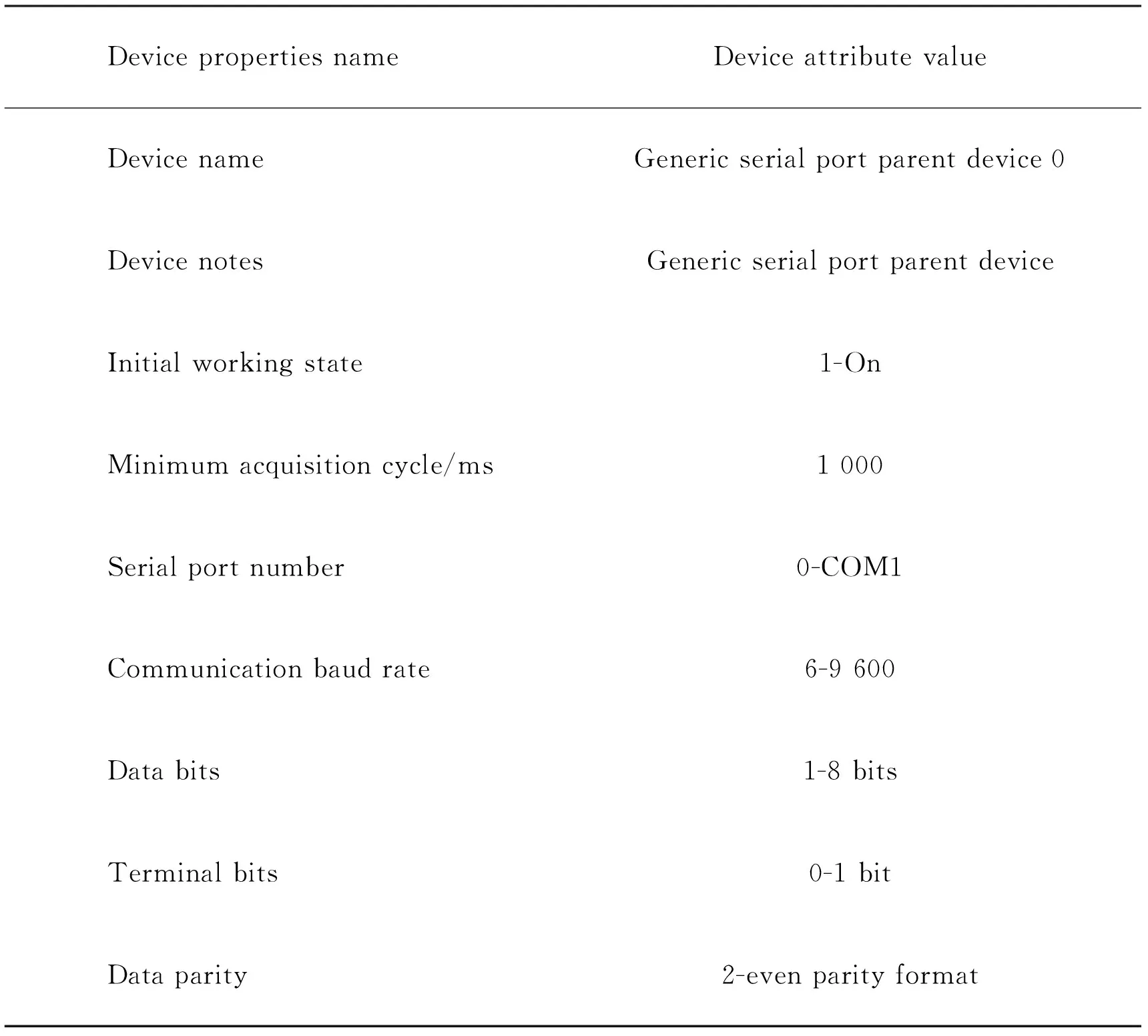
Table 2 Generic serial port parent device 0 settings
In the configuration environment device window of MCGS, the general serial port parent device 1 was assigned to the temperature controller through Modbus protocol, and set the connection parameters of the temperature controller, as shown in Table 3.

Table 3 Generic serial port parent device 1 settings
3.3Instrumentation communication setting
1) Siemens S7-200 parameters
Since the M area of Siemens PLC has no corresponding address in Modbus address. MOV-W instruction can be used to transfer the address of M area to V area. As the internal data address of PLC was less and the continuity was high, the block acquisition mode adopted the maximum length to improve the data transmission efficiency. The communication parameters of PLC as shown in Table 4.
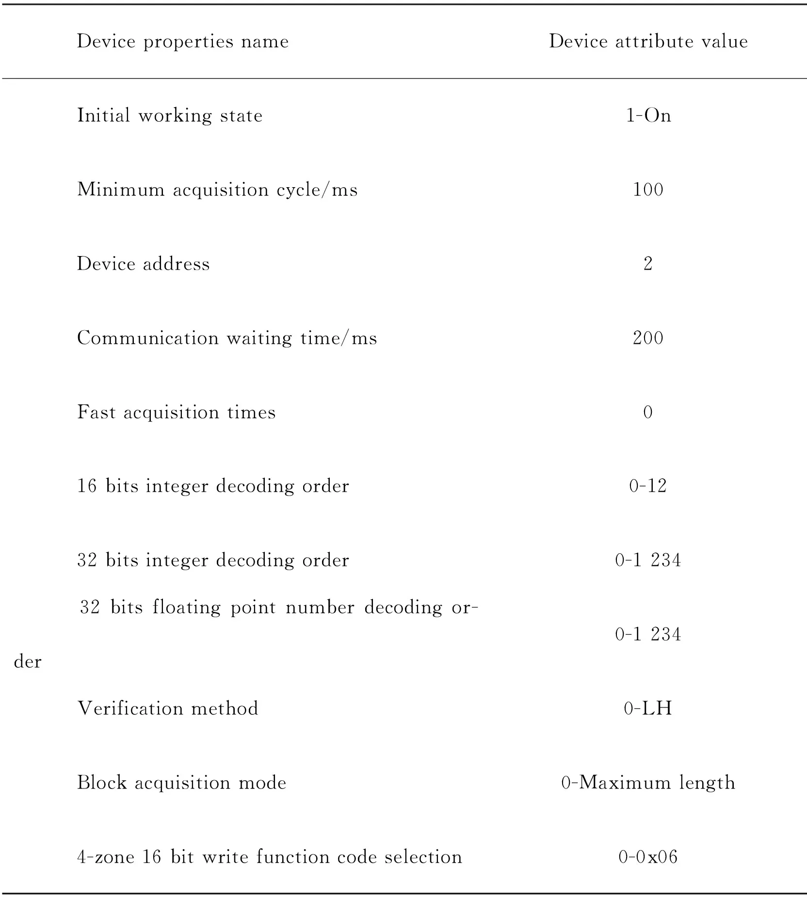
Table 4 The communication parameters of PLC
2) Temperature controller parameters
The stop heating flag of temperature controller is program temperature or time, the parameter is set to -121. The data type of Modbus input register and output register address shall be 16 bit signed binary, otherwise the negative value parameter cannot be read in the MCGS. The internal data of the temperature controller cannot be collected at one time, so it is collected by the continuous address of the data. The specific settings is shown in Table 5.
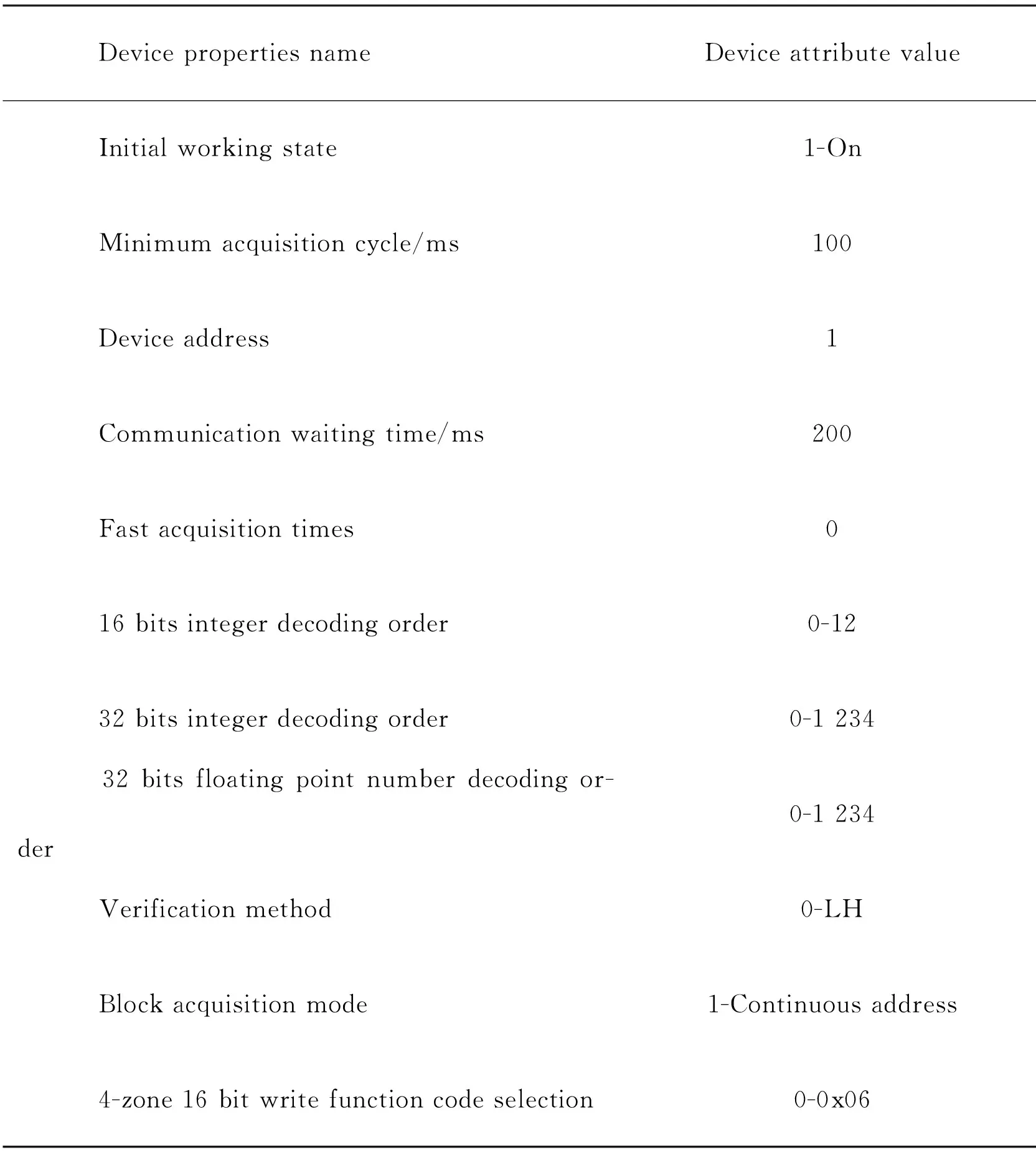
Table 5 The communication parameters of temperature controller
3.4Communication program of PLC
Siemens S7-200 needs to use the following commands to realize the Modbus RTU function.
MBUS_INIT: This command is used to enable and initialize or disable the Modbus communication function of S7-200, and executed each time the scan and the En input is on. Executing the command every time when the communication state changes. Therefore, the En input could be set to execute only at the first scan, SM0.1 command is used to realize the function, scan the network only once when the level changes.
MBUS_Slave: Enable the slave function of Modbus.
The S7-200 command network was shown in Figure 2.

Figure 2 S7-200 network
4 System structure
Figure 3 is the structure of remotely monitoring system of ceramic kiln. Which contains Siemens S7-200 PLC, 220 V convert 24 V power supply and IOT gateway. PLC is powered by 220 V voltage, Port 0 serial port is designated as Modbus communication port. Which connected with MCGS through RS485 to RS232 interface. Port 1 serial port is connected to IOT gateway, and the working parameters of MCGS can be transmitted to IOT gateway through PLC, then upload to the cloud platform.

Figure 3 System structure
5 Experimental result
5.1Field monitoring
The system has been installed and operated in a ceramic electric kiln. The actual temperature and program temperature of the kiln and the temperature of each program section can be observed through the MCGS. The screen also has various operation functions, such as controlling the operation stop state of the kiln, intelligently adjusting SV parameters, selecting common temperature rise curves, etc, shown in Figure 4.
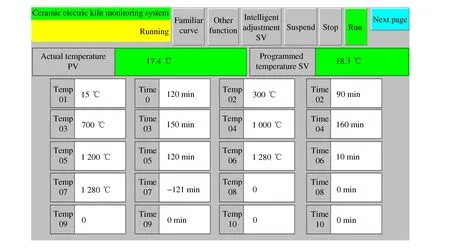
Figure 4 Parameters of field monitoring
The control functions of kiln drainage cover are integrated in the screen, and automatic control or manual control can be selected, shown in Figure 5. In automatic mode, the closing temperature of the drain cover needs to be set.
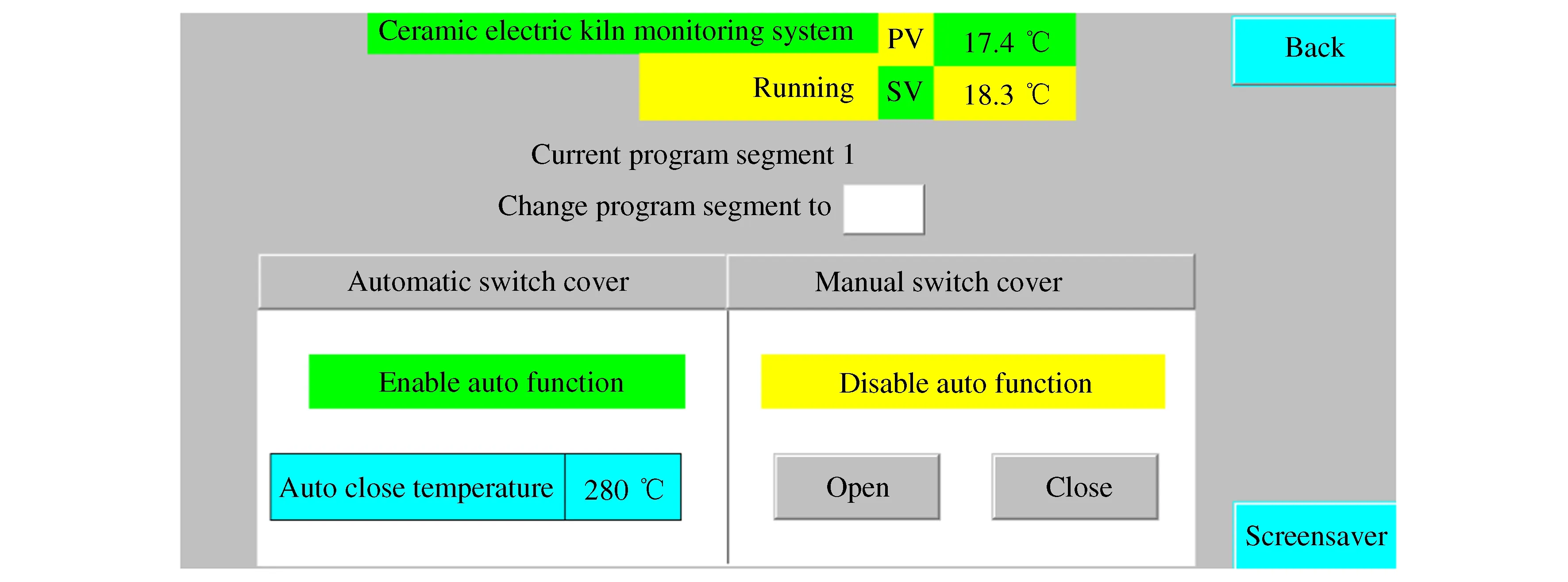
Figure 5 The interface of touch-screen control drainage
5.2Remotely monitoring
The kiln work information can be monitored in real time after logging into the cloud platform through the terminal equipment. The cloud interface can display the current actual temperature, program control temperature, operation status and other parameters of the kiln. In addition, the kiln can be remotely controlled, such as opening or closing the drainage cover, starting or stopping the kiln operation, intelligently adjusting the program temperature and viewing the firing curve parameters. The cloud platform interface is shown in Figure 6.
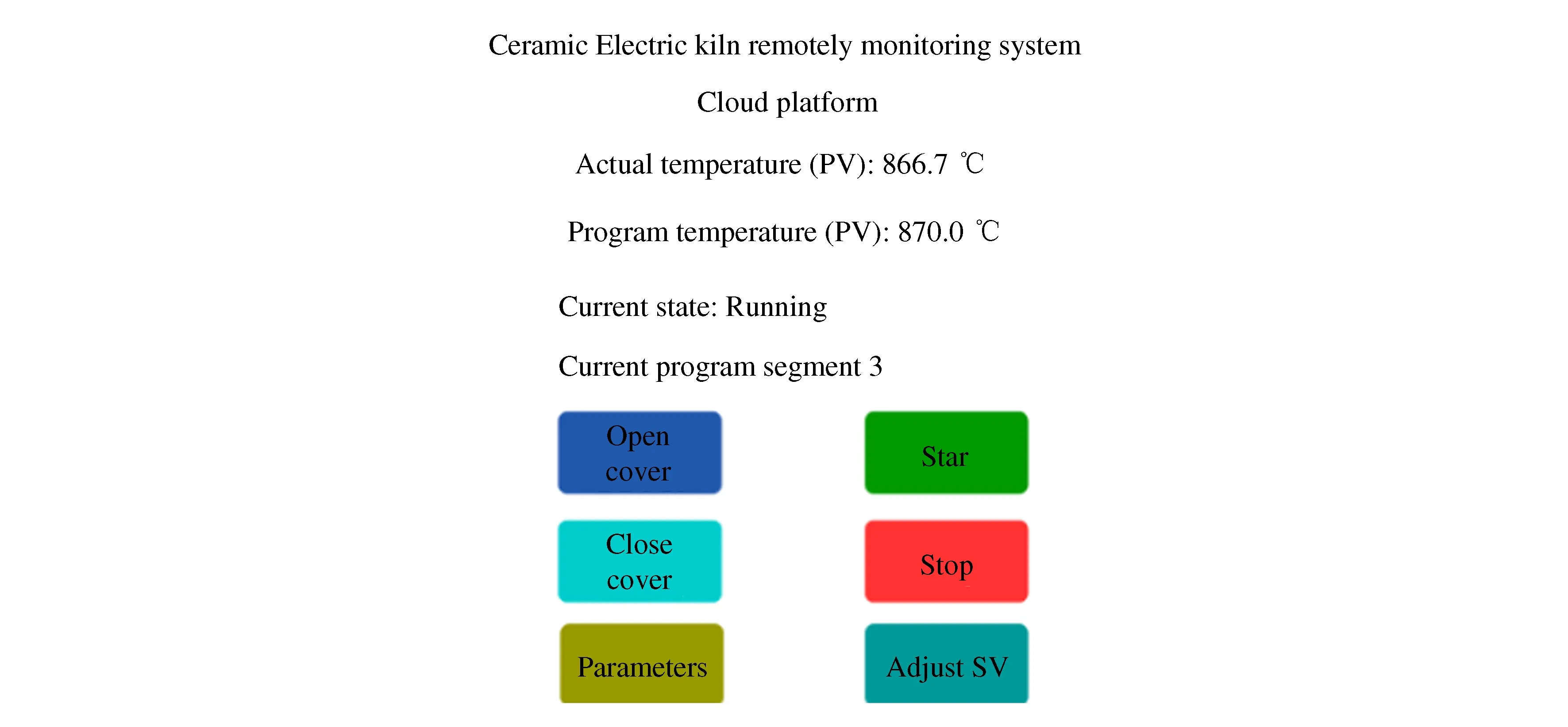
Figure 6 Cloud platform interface
6 Conclusions
1) The ceramic electric kiln remote monitoring system proposed in this paper first studies the data acquisition and monitoring system structure, then designs the hardware configuration, communication protocol parameters and communication program in the system, and verifies the effectiveness of the monitoring system through its application in the production area.
2) The temperature control instrument, MCGS, Siemens PLC and IOT gateway are combined with Modbus protocol through RS485 bus to successfully realize the communication among different instruments. The adopted technical methods can provide a certain reference for remote monitoring of similar industrial equipment.
