Modeling Technique of the Aircraft Unsteady Aerodynamics Due to the Travelling Gust
2022-06-27JINGZhiweiTANGChu
JING Zhiwei, TANG Chu
(1. General Configuration and Aerodynamics Design Department, Xi′an Aircraft Design Institute, Xi′an 710089, China; 2. Unmanned System Research Institute, Northwestern Polytechnical University, Xi′an 710072, China)
Abstract:The main equations for computing the unsteady aerodynamics of the aircraft undergoing the travelling gust are derived. Research and simulation on a specific example aircraft are performed, the results indicate that the modeling technique of the aircraft unsteady aerodynamics is correct, and it can meet the requirements due to the head-on and tail-on travelling gusts.
Keywords: travelling gust; elastic aircraft; unsteady aerodynamics; doublet lattice method
1 Introduction
Compared with the traditional gust, the travelling gust is quiet special and has some differences:
1) The travelling gust is characterized by high propagating speed and generally expands at supersonic or sonic speed, while the propagation speed of the traditional gust is often neglected.
2) Since the travelling gust has a higher gust velocity than the traditional gust, the disturbance energy carried by the travelling gust is stronger.
3) The velocity of the travelling gust is spatial and it can disturb the aircraft along both the heading direction and normal direction.
Especially when the travelling gust envelops the aircraft from the tail at the sonic speed, shown in Figure 1, the relative velocity is not very high, therefore the empennage will be affected first by the gust and then the wing gets disturbed. Such a disturbance process will first produce a nose-down pitching moment on the aircraft, which is different from that of the traditional gust. So it is interesting to study the aircraft aerodynamic force due to the travelling gust.
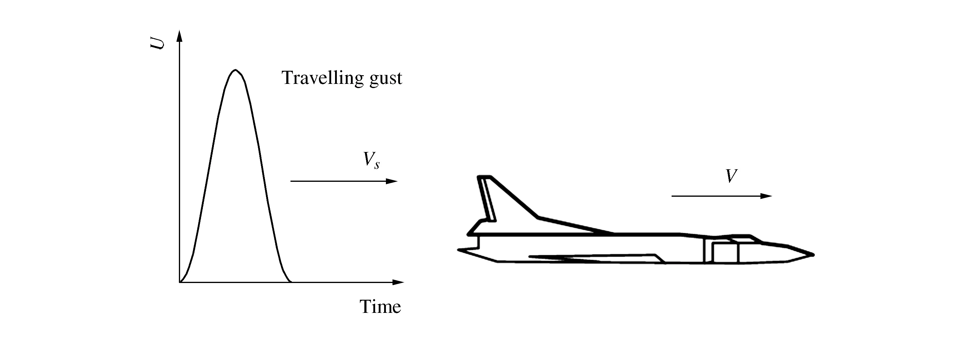
Figure 1 Situation of the travelling gust chasing a flying aircraft
Since the unsteady aerodynamics calculation technique of the aircraft in the traditional gust environment can not deal with the situation of the travelling gust chasing one flying aircraft, it is necessary to conduct the unsteady aerodynamics modeling research so as to satisfy the requirement of computing aircraft aerodynamic force caused by the travelling gust[1-4].
2 Doublet lattice method for subsonic aerodynamics
The doublet lattice method (DLM) is the key and fundamental technique to determine the unsteady aerodynamic force on the aircraft. For the elastic aircraft, both rigid modes and elastic modes are employed to calculate the subsonic aerodynamics. While using DLM to calculate the steady and unsteady aerodynamics, the first process is to divide the lifting surface of the aircraft into small trapezoidal panels, which are illustrated in Figure 2. The two sides of each panel should be parallel to the airflow.
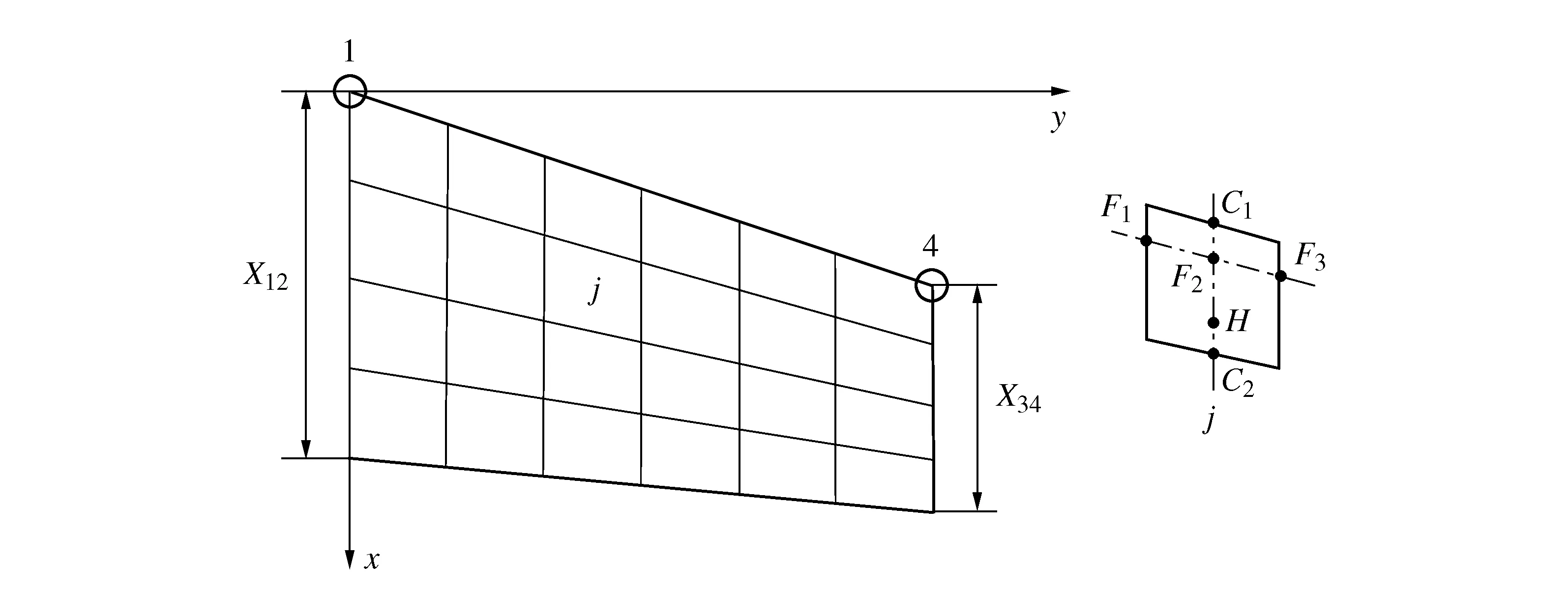
Figure 2 Schematic diagram of lifting surface for unsteady aerodynamics
In Figure 2, for any grid numberedj, the aerodynamic force of the grid acts at 25% of the medium line of the panel, which is named pressure center marked as pointF2, and the aerodynamic boundary condition should be satisfied at 75% of the medium line of the panel, which is called the downwash collocation point (control point) marked as pointH.
Based on the fundamental theory of linear aerodynamics, the integral equation should be satisfied at the downwash control pointHof theithpanel.

(1)

For all the aerodynamic panels of the lift surface, the Equation (1) can be rearranged as matrix format
DΔCp=w
(2)
Where: ΔCpis the pressure coefficient column vector at all pressure points;wis the downwash velocity column vector at all control points;Dis aerodynamic influence coefficient matrix, each element ofDis determined as

(3)
When the downwash speed at each control point is obtained, the pressure coefficient column vector will be calculated based on the following Equation.
ΔCp=D-1w
(4)
3 The aircraft unsteady aerodynamics due to the travelling gust
According to the propagating direction of the travelling gust, they can be classified into two types of wind fields:
1) Head-on travelling gust, which envelops the aircraft from the nose first.
2) Tail-on travelling gust, which overtakes the aircraft and envelops it from the tail first.
The aircraft unsteady aerodynamics due to the two types of the travelling gust are researched and computed as follows.
3.1Downwash by the head-on travelling gust
The head-on travelling gust is shown in Figure 3,x0is the initial position of the travelling gust, theXcoordinate of theithaerodynamic panel control point is marked asxi, then its distance from the travelling gust isxi-x0.
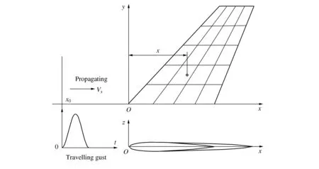
Figure 3 Schematic diagram of a head-on travelling gust
The downwash gust atxiis

(5)
Where:Uzis the vertical component of the travelling gust velocity;Uzi(t) is vertical gust velocity of theithpanel at timet;Vis the flight speed of the aircraft; Δtiis the time lag between theithpanel downwash control point and the initial position of the travelling gust, and it is calculated as

(6)
Where,VΔis the enveloping speed of the head-on gust to the aircraft, and it is defined as
VΔ=VS+V
(7)
Where,VSis the sound speed.
The frequency domain counterpart of Equation (5) is

(8)
Where,kis the reduced frequency related with the reference lengthLand vibration frequencyω, and it is defined as

(9)
Then the resulting downwash vector due to the head-on travelling gust with amplitudeUz(iω) and a reference pointx0is
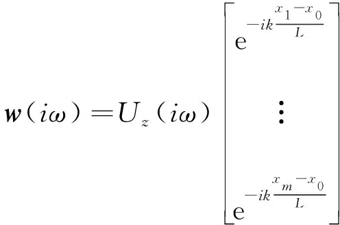
(10)
Where,mis the number of aerodynamic meshes.
3.2Downwash by the tail-on travelling gust
Figure 4 illustrates the tail-on travelling gust,x0is the initial position of the travelling gust. Theithaerodynamic panel control point can be labeled asxi, then its distance from the travelling gust isxi-x0.
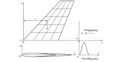
Figure 4 Schematic diagram of a tail-on travelling gust
The downwash atxiis

(11)
Where, Δtiis calculated according to Equation (6), however the enveloping speed of the tail-on travelling gust to the aircraft is defined as
VΔ=VS-V
(12)
The frequency domain counterpart of Equation (11) is

(13)
The resulting downwash vector due to the tail-on travelling gust is
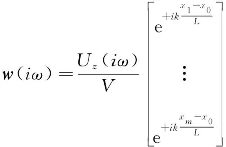
(14)
3.3A hybrid approach of the aerodynamic force due to the travelling gust
To sum up, the downwash vector caused by the head-on travelling gust or the tail-on travelling gust can be synthesized as
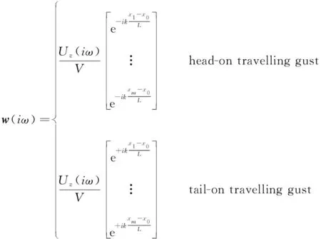
(15)
Substituting Equation (15) into Equation (4), and then by left-multiplying the panel area matrix and mode matrix, the generalized aerodynamic force coefficient (GAFC) vector due to the travelling gust can be obtained as
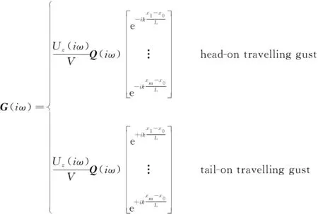
(16)
Where,Qw(iω) is the generalized aerodynamic influence coefficient (GAIC) matrix induced by the travelling gust.
By utilizing the inverse Fourier-Transform approach ofG(iω), it yields the time domain GAFC

(17)


(18)
It should be pointed out that a hybrid approach, as demonstrated above, is taken to obtain the time domain unsteady aerodynamic force of the aircraft encountered the travelling gust while avoiding the requirement for the rational approximation of the gust excitation. First, the travelling gust velocity in time domain is transformed to the frequency domain through the Fourier-transform. Then, the frequency domain travelling gust velocity is left multiplied by the frequency domain GAFC vector due to the travelling gust, thus the frequency domain GAFC vector can be obtained. Finally, the inverse Fourier-transform of the frequency domain GAFC matrix is performed, so as to get the GAFC vector in time domain, note that the flight dynamic pressure should be applied to the GAFC.
Since the hybrid approach has avoided the rational aerodynamic approximation of the gust excitation, it can effectively ensure the calculation accuracy of the aircraft unsteady aerodynamic force caused by the travelling gust[7].
4 Simulation results and discussion
4.1The example aircraft and its main parameters
The example aircraft is a large twin-engine civil transport aircraft. The finite element model of the aircraft is composed of beam elements and concentrated mass points, as depicted in Figure 5.
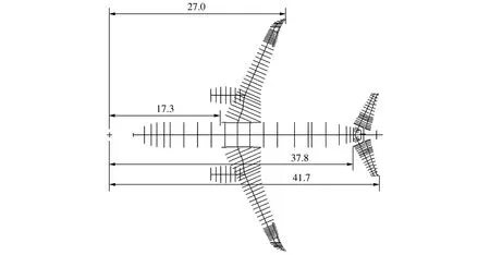
Figure 5 The finite element model of the example aircraft
Modal analysis was carried out on the aircraft, and some symmetrical mode parameters are shown in Table 1. Generally, the selection of elastic modes up to 20 Hz can meet the requirement of the dynamics modeling and analysis.
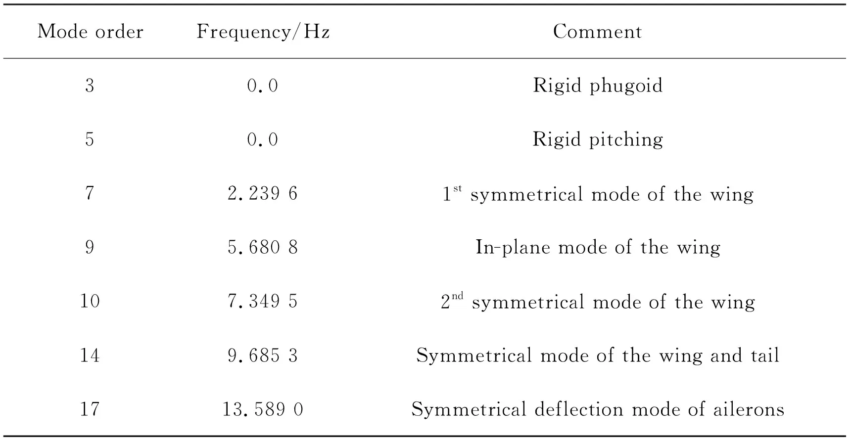
Table 1 Main symmetric mode parameters of the example aircraft
Aerodynamic model used for steady and unsteady aerodynamics calculations of the aircraft is illustrated in Figure 6.

Figure 6 The aerodynamic model of the example aircraft
The main simulation parameters of the aircraft are shown in Table 2, and the velocity profile of the travelling gust is shown in Figure 7, which has the ‘1-cosine’ profile. For the tail-on travelling gust, the enveloping speed on the aircraft is 150 m/s. For the head-on gust, it is treated as a traditional gust, and then it also envelops the aircraft at the speed of 150 m/s. Note that the directions of the enveloping velocity are different in the two cases.
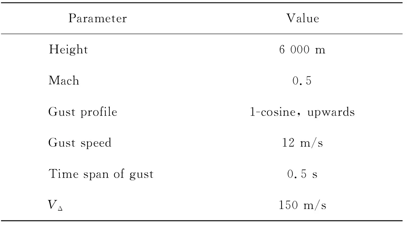
Table 2 Main simulation parameters
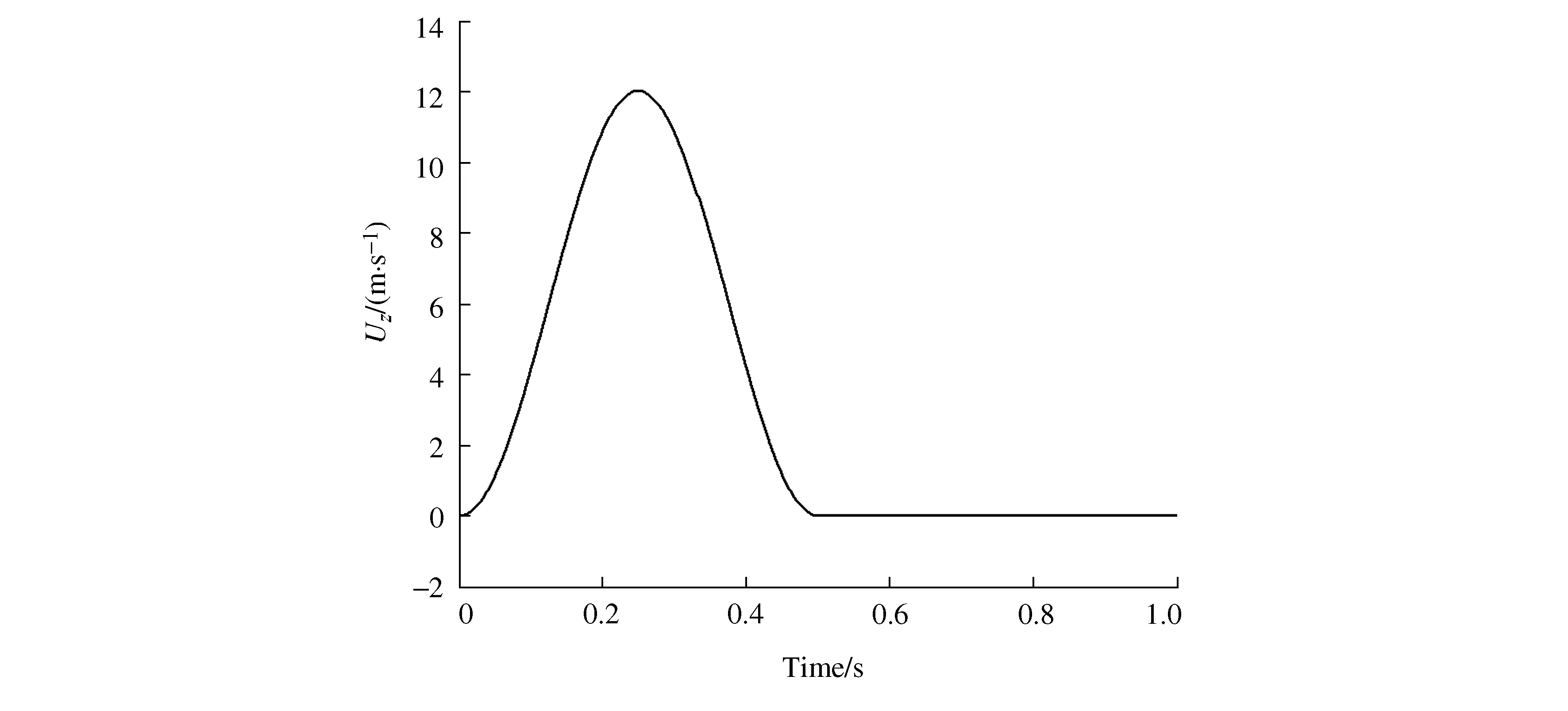
Figure 7 The velocity profile of the travelling gust
In addition, the initial location of the head-on travelling gust isx0=0, while the tail-on travelling gust initially locates atx0=42 m.
4.2The generalized aerodynamic force due to the travelling gust
According to the simulation parameters in Table 2 and the velocity profile of the travelling gust defined in Figure 7, the generalized aerodynamic force of the aircraft in the travelling gust environment was calculated.
It should be noted that the basic units of the aircraft finite element model are mm and g. The generalized aerodynamic force curves of the 3rd, 5th, 7thand 10thmodes of the aircraft are demonstrated in Figure 8-Figure 11. For the rigid phugoid mode (Figure 8) and the rigid pitching mode (Figure 9), the tail-on travelling gust tends to increase the generalized aerodynamic force, which may lead to an increase in the dynamic response result of the aircraft.
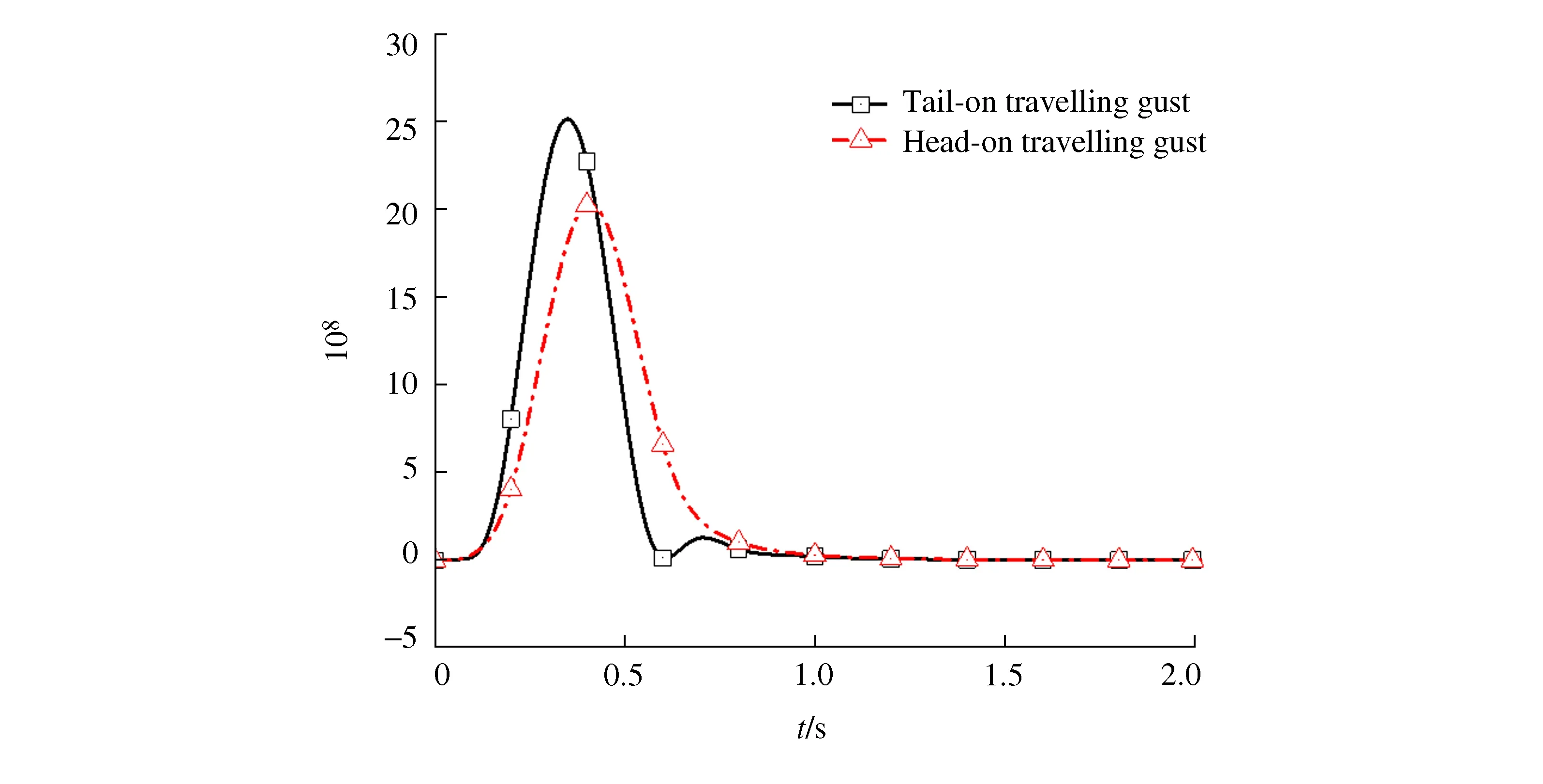
Figure 8 The generalized aerodynamic force of the 3rd mode
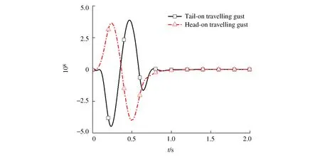
Figure 9 The generalized aerodynamic force of the 5th mode
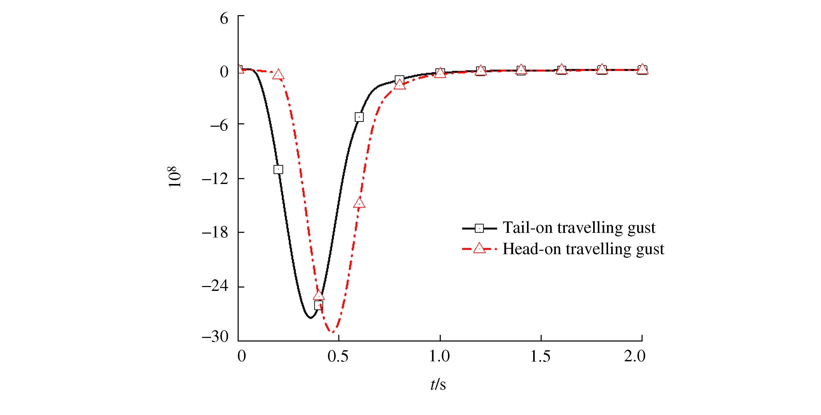
Figure 10 The generalized aerodynamic force of the 7th mode

Figure 11 The generalized aerodynamic force of the 10th mode
In addition, it can be seen from Figure 9 that when the head-on wind acts on the aircraft, the generalized aerodynamic force of the rigid body pitching mode first presents a trend of nose-up change and then nose-down change. However, when the tail-on travelling gust is applied to the aircraft, the generalized aerodynamic force of the rigid body pitching mode first reveals a trend of nose-down change and then nose-up change, which is contrary to the head-on travelling gust. Actually the above specific phenomena properly reflect the pitching moment of the aircraft in the head-on and tail-on travelling gusts.
4.3The aircraft aerodynamic force validation
In order to verify the unsteady aerodynamics calculation technique of an elastic aircraft in the travelling gust environment presented in this paper, some special treatments are needed for the example aircraft: the elastic vibrations of the aircraft structure and the freedoms of rigid body motion are constrained so as to eliminate the contribution of the aircraft′s own motions and vibrations to the aerodynamics.
It should be mentioned again the typical geometric dimensions of the aircraft shown in Figure 5, the leading edge point of the wing root isX=17.3 m, the trailing edge point of the wing tip isX=27.0 m, the leading edge point of the horizontal tail root is 37.8 m, the trailing edge point of the horizontal tail tip is 41.7 m.
The main parameters used in the validation are shown in Table 2, it is considered that the enveloping velocity is 150 m/s for both the head-on travelling gust and tail-on travelling gust. The starting position of the head-on travelling gust isx0=0 m, while the starting position of the tail-on travelling gust isx0=42 m.
In the head-on travelling gust, the aerodynamic bending moment of the wing and horizontal tail is shown in Figure 12. The curves depict that the empennage is affected by the gust a little later than the wing, which reflects the enveloping process of head-on travelling gust from the wing to the empennage.
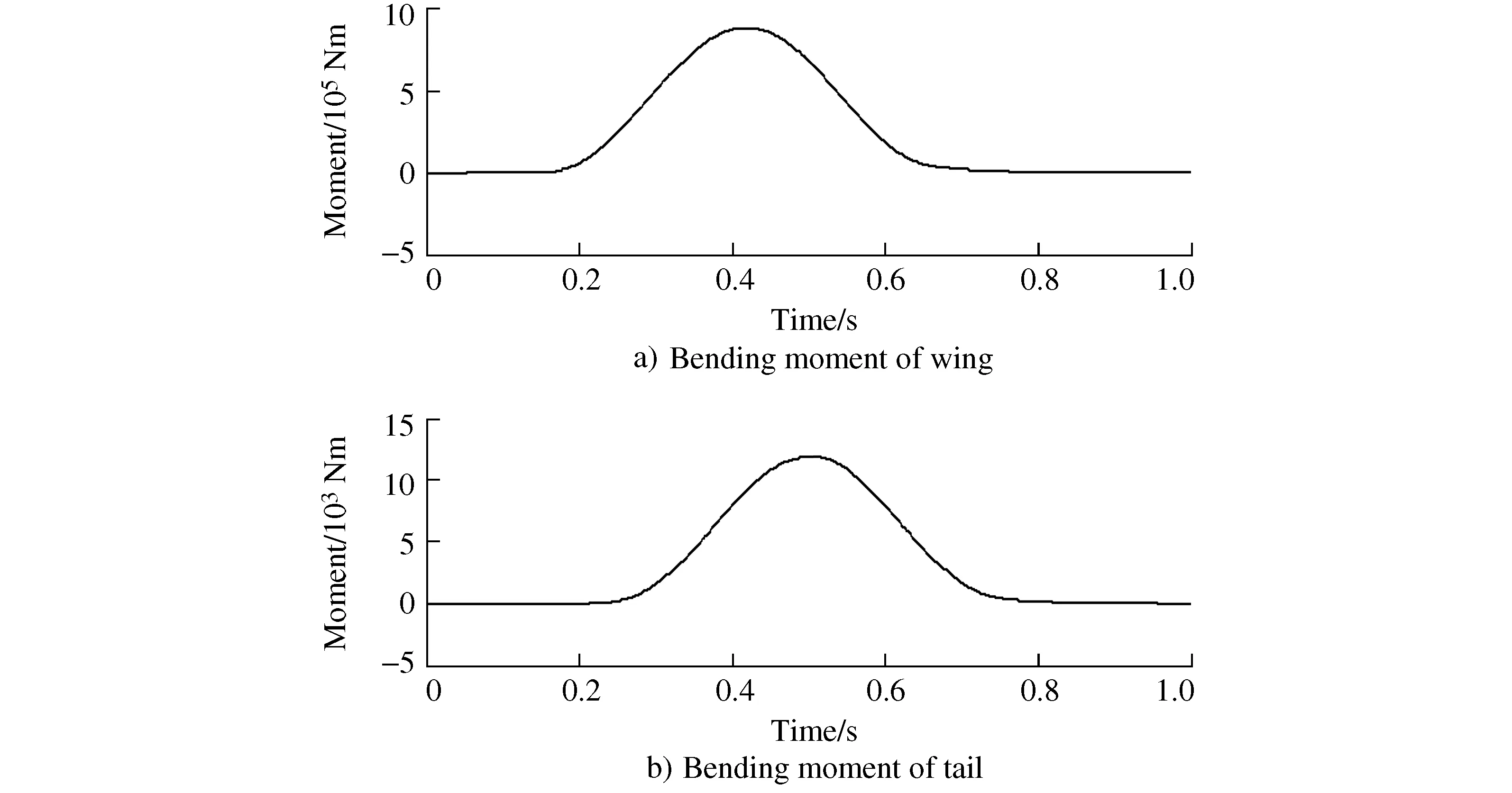
Figure 12 The aerodynamic moment of the wing and the tail in the head-on travelling gust
In the tail-on travelling gust, the aerodynamic bending moment of the wing and horizontal tail is shown in Figure 13. It can be seen from the figure that the wing is influenced by gust about 0.1 s later than the empennage, and this reflects the enveloping process of tail-on travelling gust from the empennage to the wing. It should be emphasized that when the travelling gust acts on the wing, it will also induce downwashes on the empennage, which would decrease the aerodynamic force on the empennage.
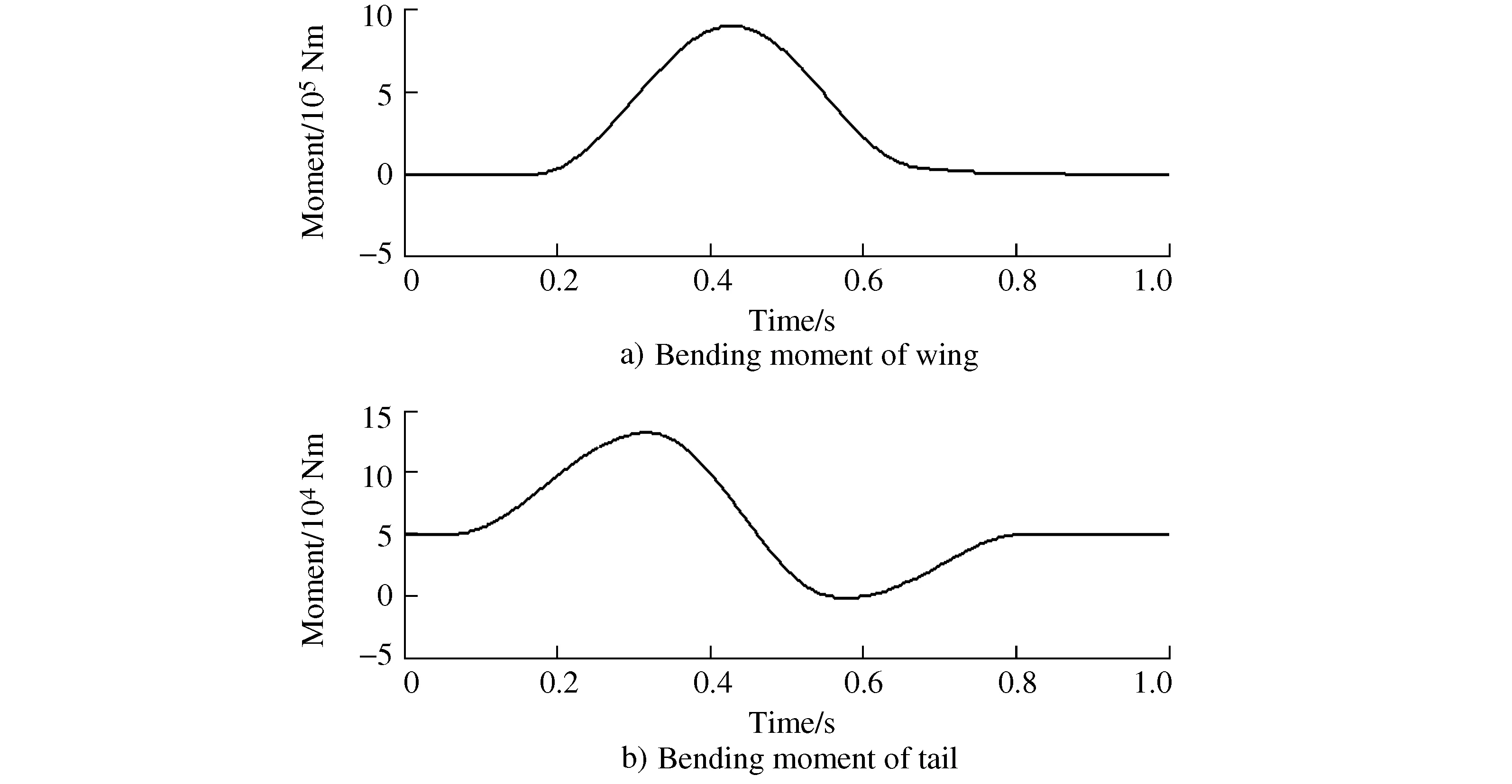
Figure 13 The aerodynamic moment of the wing and the tail in the tail-on travelling gust
The results of the above verification examples show that the unsteady aerodynamic force calculation technique established in this paper can reasonably consider the process of enveloping the aircraft by the travelling gust, and it can not only meet the calculation requirement of the aircraft in the traditional head-on gust, but also meet the requirement due to the tail-on travelling gust.
5 Conclusions
1) The unsteady aerodynamics calculation technology of the aircraft in the travelling gust is established, which can meet the needs caused by the head-on travelling gust and the tail-on travelling gust simultaneously.
2) The generalized aerodynamic force of the mode demonstrates a good trend, and it accords with the aerodynamic characteristics of the aircraft in the travelling gust.
3) Specific examples are established and simulations are conducted, the results show that the aircraft unsteady aerodynamic calculation technique is correct and can satisfy the requirements of engineering design.
