A joint optimization algorithm for focused energy delivery in precision electronic warfare
2022-04-19ZhongpingYangShuningYangQingsongZhouJianyunZhangZhihuiLiZhongruiHuang
Zhong-ping Yang, Shu-ning Yang, Qing-song Zhou, Jian-yun Zhang, Zhi-hui Li,Zhong-rui Huang
College of Electronic Engineering, National University of Defense Technology, He Fei, China
Keywords:Focused energy delivery Localization error Particle swarm optimization Precision electronic warfare Unimodular quadratic program
ABSTRACT Focused energy delivery(FED)is a technique that can precisely bring energy to the specific region,which arouses wide attention in precision electronic warfare (PREW). This paper first proposes a joint optimization model with respect to the locations of the array and the transmitted signals to improve the performance of FED. As the problem is nonconvex and NP-hard, particle swarm optimization (PSO) is adopted to solve the locations of the array,while designing the transmitted signals under a feasible array is considered as a unimodular quadratic program (UQP) subproblem to calculate the fitness criterion of PSO.In the PSO-UQP framework established,two methods are presented for the UQP subproblem,which are more efficient and more accurate respectively than previous works.Furthermore,a threshold value is set in the framework to determine which method to adopt to take full advantages of the methods above.Meanwhile, we obtain the maximum localization error that FED can tolerate, which is significant for implementing FED in practice. Simulation results are provided to demonstrate the effectiveness of the joint optimization algorithm, and the correctness of the maximum localization error derived.
1. Introduction
Focused energy delivery(FED)is a widely concerned technique in many fields.The goal of this technique is bringing the energy to the intended area, while preventing some other areas not being affected. Similar technologies, such as transmit beamforming technique,are applied in radar and communication fields[1-4],but the objective is to focus the energy onto a specific range of angles rather than an area.Due to the outstanding properties,FED plays an important role in precision electronic warfare(PREW).The concept of PREW is first proposed by Strategic Technology Office (STO) of the US Defense Advanced Research Projects Agency (DARPA) [5],which aims to solve a series of problems in the traditional electronic warfare, such as low energy utilization, easy detection by enemy reconnaissance equipment,and accidental electromagnetic injuries to collateral devices[6].The purpose of PREW is to present the effect of surgical jamming, which means jamming the target equipment and not affecting the friendly devices nearby.
To the best of our knowledge,papers in this field are limited.The existing methods are mainly inspired by the waveform diversity technique for MIMO systems as discussed in Refs. [7-11]. The authors of [12] are the first to establish a semidefinite programming(SDP) model of FED and address the problem by designing the covariance matrix of the transmitted signals. In Ref. [13], the authors modify the model by taking full advantages of the prior information on the locations of the regions,and they reformulate the problem with two performance metrics. Reference [14] converts the model into a unimodular quadratic program (UQP), which is a common model in many fields [15-17], and designs the codes of the transmitted signals, which further improves the indicators of FED and the computational complexity. However, the existing papers only design the transmitted signals under a certain array.They neglect the effect of the locations of the array on performance,which leads to the waste of the optimization dimensions.When we implement FED by designing the signals merely,the performance is poor in some complex scenarios, where the target regions locate nearby the protected regions.In this case,the energy must change rapidly in spatial,and the models aforementioned in Refs.[12-14]cannot meet the requirement because of the limits on the degree of freedom. Meanwhile, the energy in the collateral areas is high,which causes the unexpected jamming to the collateral devices.
Therefore, it is necessary to take the locations of the array into consideration, which is an array optimization problem in FED substantially. As to the references about the array optimization,they focus on solving the optimal distance or angles for the intended beampattern. Considering that the problems are usually non-linear and nonconvex with some complicated constraints, researchers mainly adopt the intelligence algorithms as discussed in Refs.[18-25].Due to its efficiency and convergence,particle swarm optimization (PSO) is often adopted in various models [26-29].However,the problem of the array optimization in FED,which boils down to the joint optimization problem with respect to the transmitted signals and the locations of the array,is not involved in the existing papers and models. Meanwhile, when adopting PSO to solve the joint optimization problem directly, the computational complexity of the algorithm is extremely high,because the feasible region of the transmitted signals is a high dimensional complex space.
To address the problems above, this paper establishes a joint optimization model with respect to the locations of the array and the transmitted signals. It needs emphasizing that the constraints involve the ultra-sparsity of the array and the constant modulus of the signals, which guarantee the precision of the focused region and the maximum power of the transmitters respectively. As the joint optimization problem is nonconvex and NP-hard,we propose an algorithm based on the PSO-UQP framework for the model,where the locations of the array are optimized by PSO, while designing the transmitted signals under the current array is considered as a UQP subproblem. Two methods with different advantages are presented for solving the UQP subproblem, and then a threshold value is set in the algorithm framework to determine which method to adopt. Furthermore, we derive the maximum localization error that FED can tolerate in practice. The contributions of this paper are summarized as follows:
(1) Differing from the existing papers that only design the transmitted signals in FED,we establish a joint optimization model with respect to the transmitted signals and the locations of the array, which has greater degrees of freedom in the model and better performance in the simulation results compared to previous works.
(2) Regarding the UQP subproblem, we present two methods with different advantages over the Majorization-Minimization (MaMi) framework in Ref. [14]. The first method estimates the optimal value of UQP as the fitness criterion of PSO, which has much lower computational complexity.The second method avoids the divergence when adopting the MaMi framework.
(3) In the PSO-UQP framework, we take full advantages of two methods aforementioned to accelerate the algorithm. A threshold value is set to determine which method to adopt to calculate the fitness criterion of PSO, where the traditional hybrid PSO framework usually adopts one method and cannot guarantee the efficiency and the accuracy simultaneously. Simulation results reveal the superiority of our algorithm framework.
(4) Considering the inevitable localization errors,we derive the maximum localization error that FED can tolerate, which is significant to implement FED in practice and the systematic design of PREW, and the correctness of the result is demonstrated in the simulation results.
The remainder of this article is organized as follows: Section 2 establishes the model and formulates the joint optimization problem in FED. Section 3 proposes the algorithm for the joint optimization problem and the PSO-UQP framework. Section 4 presents the maximum localization error and provides the detailed derivation process. The simulation results in Section 5 reveal the performance of the proposed algorithm and the correctness of the maximum localization error derived.Section 6 gives the conclusion.
2. Problem formulation
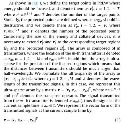
In this paper,we give the assumptions regarding to the steering vector as follows:
(1) The signals propagate in free space with no reflection or scattering, such as multipath fading or shadowing.
(2) Each node is time-synchronized with a precise oscillator synchronized to the same carrier frequency.
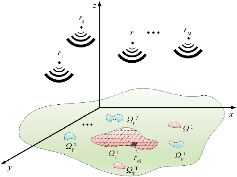
Fig.1. The spatial model of PREW.
These assumptions are typical for the study of the distributed sparse array as discussed in Refs.[30-32],which is also appropriate for the steering model in FED. Thus, the steering vector from the array r to the point σ is given by:
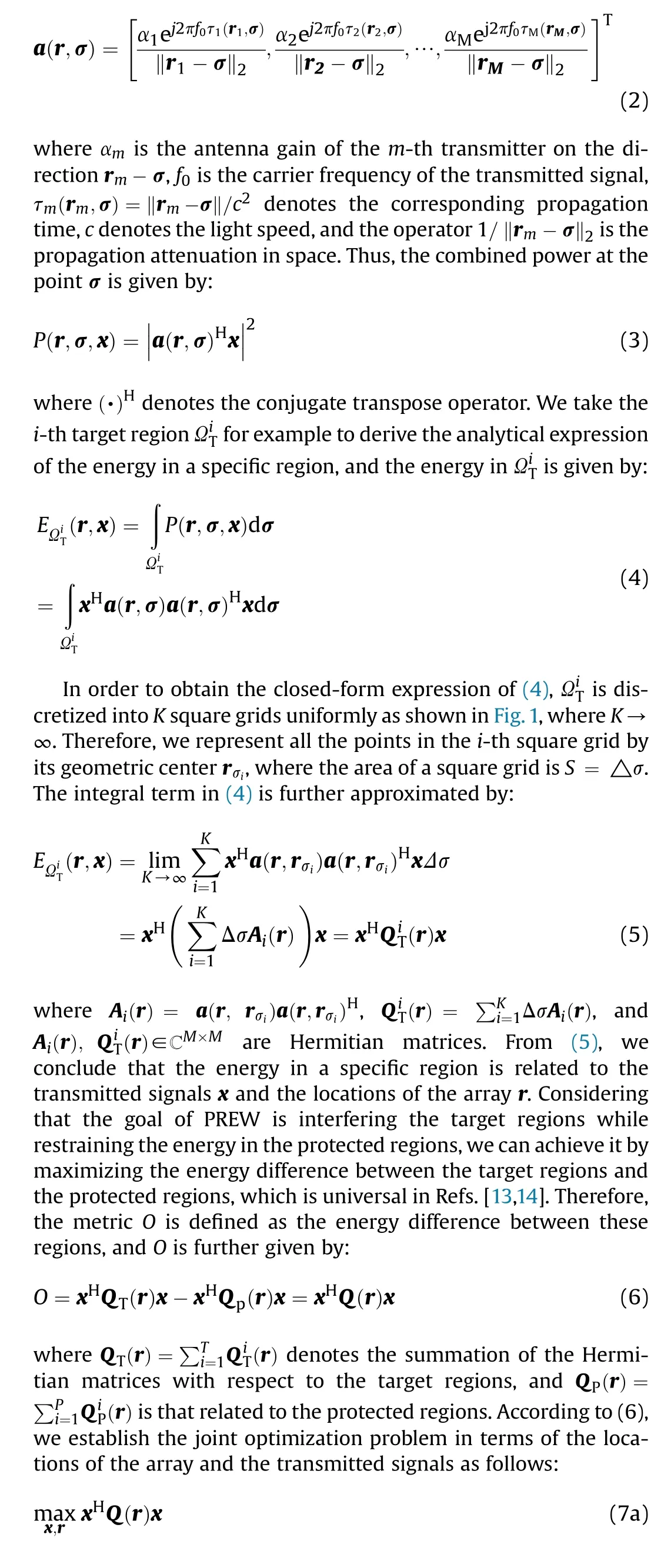

where x(i) denotes the i-th element of the vector x, and the constraint (7.b) is to ensure that the power of each transmitter is maximum and normalized by 1. The constraint (7.c) is to ensure that the array is ultra-sparsely distributed, where μ measures the sparsity and λ denotes the wavelength of the transmitted signals.
3. Algorithm design
Considering that the problem(7)is nonconvex and NP-hard,we propose a hybrid algorithm based on the PSO framework to solve it,where the locations of the array r are solved by PSO and designing the transmitted signals x is considered as a UQP subproblem for each feasible array.In this case,we propose a PSO-UQP framework for the joint optimization problem. Furthermore, two methods,which have different advantages over the MaMi framework in Ref. [14], are presented for the subproblem to calculate the fitness criterion of PSO. Differing from the traditional hybrid PSO framework that employs only one method, we set a threshold value to determine which method to adopt in order to accelerate the algorithm and guarantee the accuracy simultaneously.
3.1. The joint optimization algorithm based on PSO-UQP framework
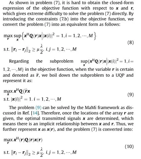
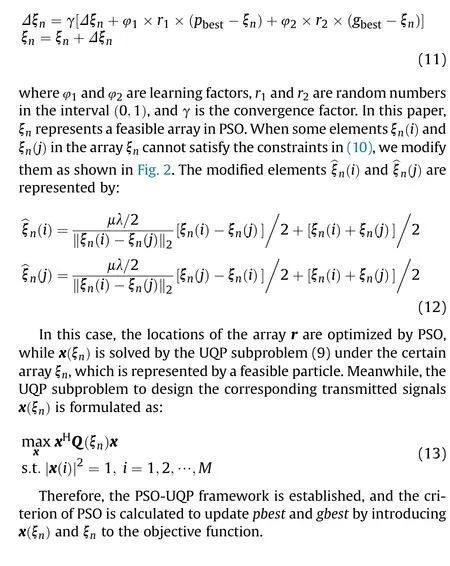
However,it is difficult to derive the analytical expression of x(r)and the objective function in (10). In this case, we adopt the PSO framework to solve problem (10). PSO is an intelligence algorithm to search the optimal solution in the complex space by the interaction of the individuals in a population of particles [33], which applies for this nonconvex and NP-hard problem. In the PSO framework, the objective function in (10) is considered as the fitness criterion. Every potential array ξ∈ℝ,n = 1,2,…,N,where N is defined as the population of particles,is considered as a feasible particle with the memory of the best location it have ever been,which is denoted as p.Similarly,gis defined as the best location that the whole population have ever been. The main properties of a feasible particle are updated as discussed in Ref. [34]:
3.2. Two methods to solve the subproblem
In the PSO-UQP framework, the subproblem can be solved by the MaMi framework as discussed in Ref. [14]. However, the computational complexity is rather high.It first converts Q(ξ)into a semidefinite matrix by calculating the maximum eigenvalue,and then introduces a series of surrogate functions to replace the objective function to search the optimum point by iteration. Thus,the computational complexity of this method is O(M+ nM),which consists of two parts. The first part O(M) is generated by calculating the maximum eigenvalue and the corresponding eigenvector of Q(ξ).The second term O(nM)is introduced by the MaMi framework,where nis the iteration steps.Though it is more efficient than the algorithms proposed in Refs.[12,13],this method still attach additional computational burden to the PSO-UQP framework. When the size of the subproblem becomes larger, the efficiency of the joint optimization algorithm is severely impacted by the method to solve the UQP subproblem.Moreover,the feasible region of x is a high dimensional complex space, which may be divergent when adopting the MaMi framework to solve the optimal solution of the subproblem. Therefore, we present two methods with different advantages to solve the UQP subproblem as the fitness criterion in this subsection.

Fig. 2. The method to modify the elements for the feasible particle.
3.2.1. A relaxation method to estimate the fitness criterion
Regarding the UQP subproblem in (13), we sum up all the M(M-1)/2 constraints together, and the subproblem is relaxed into:
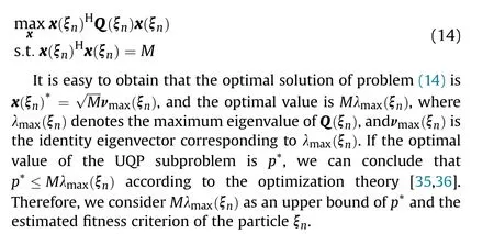
Moreover, if we calculate the maximum eigenvalue and the corresponding eigenvector directly, the computational complexity is O(M), which has an implicit decrease by O(nM)compared to the MaMi framework.In order to further improve the efficiency,we first introduce a matrix P(ξ) = Q(ξ)+ δI, where I is an M×M identity matrix and δ is a large constant. Thus, P(ξ) is an M × M order positive semidefinite matrix. Then, we adopt the power iteration method to calculate the estimated maximum eigenvalue~λ(ξ) of P(ξ). Therefore, λ(ξ) is obtained by λ(ξ) =~λ(ξ)-δ,where δ is usually 1 or 2 magnitudes larger than any eigenvalue of Q(ξ).The computational complexity of this method is O(nM), where nis the iteration steps of the power iteration method.
The relaxation method gives an estimated optimal value of the fitness criterion rather than solving pand x(ξ) directly. When there is a large optimization room for r, the PSO-UQP framework can determine the optimization direction of each particle Δξby the estimated optimal values.The impact of estimation is minimal when the growth of gis relatively large. Therefore, we can estimate the optimal value of the UQP subproblem in some iteration steps of the algorithm framework. We name this method as relaxation to estimate (RTE).
3.2.2. Dominant eigenvector-matching method
Though RTE is much more efficient than the MaMi framework,it is not accurate enough in solving the optimization direction Δξwhen the particles are close to local or global optimum points.Hence, we present the following method which is more accurate than RTE and more efficient than the MaMi framework.
We first give the definition of vector matching as follows. For two complex vectors a,b∈ℂ, a is said to be matching with b when arg[a(i)] = arg[b(i)],i = 1,2,…,N, where arg(·) denotes the argument of a complex variable[37].Considering the constraints in the subproblem,the feasible solution has the form x =[e1,e2,…,eM]. Then, the optimal solution xis matching with the eigenvector νcorresponding to the maximum eigenvalue as proved in Ref. [37], where νis calculated by the power iteration method aforementioned. Thus, xhas the closed-form expression:

This method obtains the closed-from expression of the optimal solution for the subproblem,which avoids the divergence that may exist in the iteration process of the MaMi framework. The computational complexity is O(nM +M),and it is also much lower than the MaMi framework. We name this method as dominant eigenvector-matching (DEM).
3.3. The switch method between RTE and DEM in the algorithm framework
To take full advantages of two methods aforementioned, we adopt both of them to calculate the fitness criterion in different periods of the PSO-UQP framework.We set a threshold value tv to determine which method to adopt to accelerate the algorithm. If the growth of gis larger than tv, we adopt RTE for efficiency because there is a sufficient optimization room for r and we can determine the optimization direction by the estimated fitness criterion. If the growth of gbest is lower than it, we adopt DEM for accuracy in case that the particles ignore the global or local solution. The flowchart of the PSO-UQP framework is shown in Fig. 3.
4. The maximum localization error in FED
In this section, we analyze the impact of the localization errors on the performance,and the maximum localization error is derived for FED. Considering the inevitable localization errors on the platforms of distributed array[38,39],the transmitted signals have the unexpected phase shift in the specific regions in practice, which weakens the performance of FED. When the errors are large enough, we fail to achieve the goal of FED. Therefore, it is of great significance to obtain the maximum localization error to the systematic design of PREW.
Assuming that the optimal solutions of (7) are ~r and ~x, ~O is represented by:
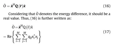
where qdenotes the i-th row and j-th column element in Q(~r),Re{·}denotes the real part of any complex number,xdenotes the i-th element of ~x, and (·)denotes the conjugate operator on any complex number.Without loss of generality,we suppose that each transmitter is equipped with an isotropic antenna, which means α=w is a constant in (2). When introducing (2) to(17), we get:
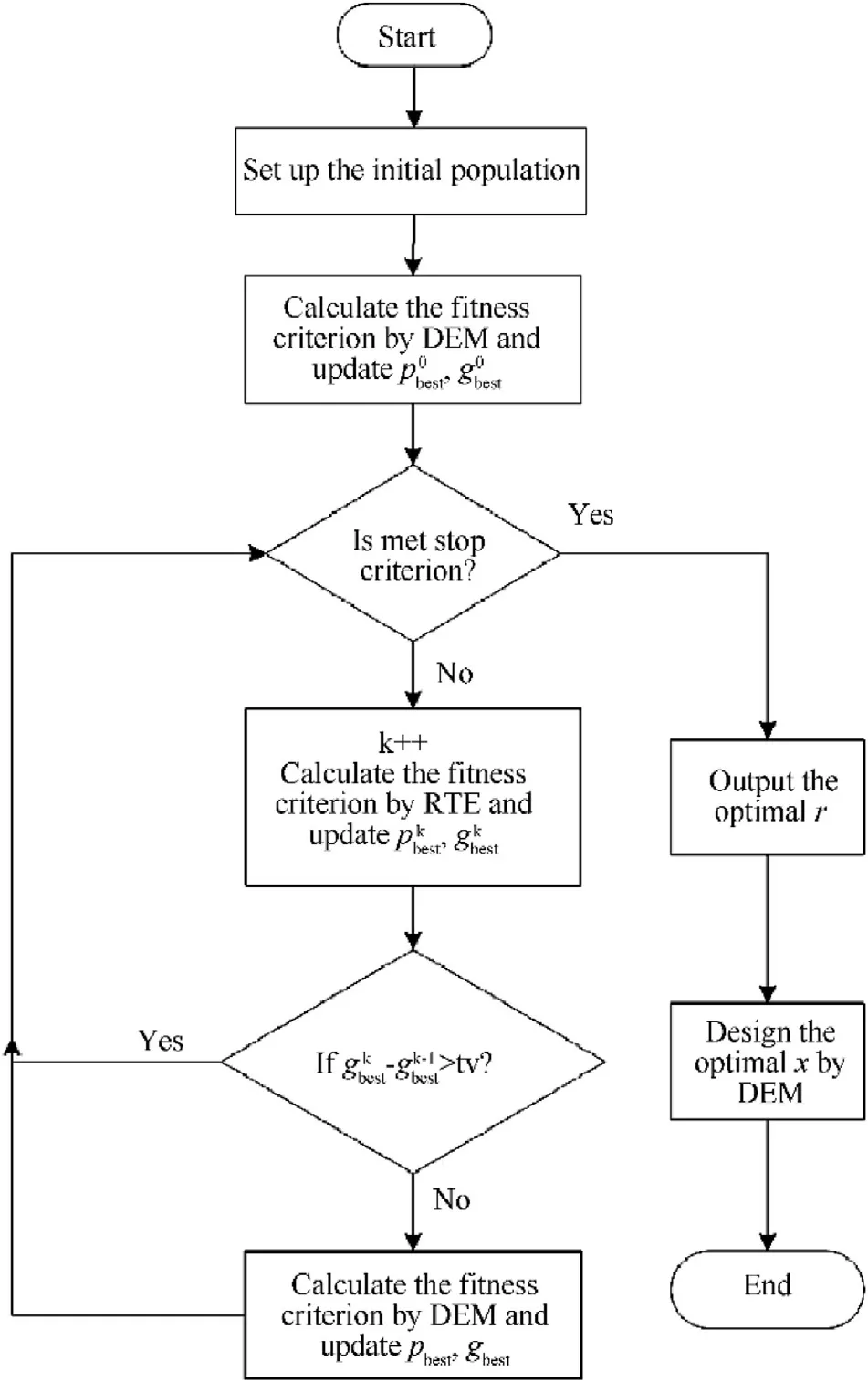
Fig. 3. The flowchart of the joint optimization algorithm based on PSO.
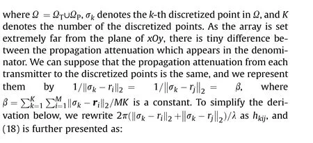


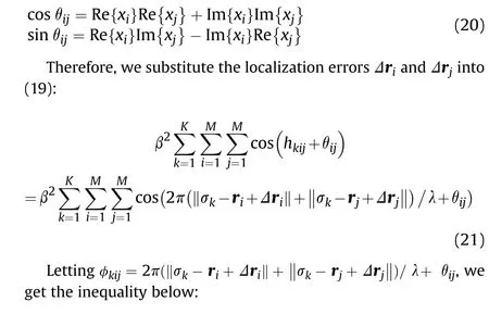
where Im{·} denotes the imaginary part of any complex number,and θis determined by xand x, which satisfies the relationship below:
It is an acceptable result for the problem, as the carrier wavelength λ is the only prior information for the array when implementing FED in different scenarios. Meanwhile, this result is of significance in practice. When the localization accuracy of distributed array is less than the maximum localization error, we can

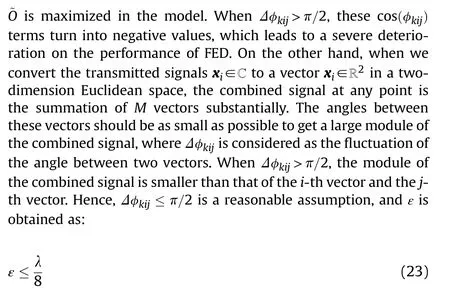
where ε denotes the maximum localization error that FED can tolerate,and satisfies the relationship ε ≥‖Δr‖.In order to ensure that there is no large fading on ~O,Δφ=4πε/λ should fluctuate in a certain range.
From the derivation above, we find that the localization errors have a non-linear impact on ~O, and it is difficult to get the closedform expression of ~O with respect to Δrand Δr. However, it is reasonable to assume that Δφ≤π/2. On one hand, most of cos(φ)terms in(21)should be obtained at relative large values as guarantee the performance of FED.
5. Simulation results
In this section,we implement several simulation experiments to show the performance of the algorithm proposed and the correctness of the maximum localization error derived. All numerical experiments are implemented on a PC with a 1.80 GHz i7-10510U CPU and 16 GB RAM via MATLAB R2016a.
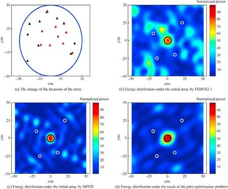
Fig. 4. The result of the joint optimization with comparison under the array consisting of M1 =10 transmitters and constraint indexes μ1 =50, rα = 30 m.
The main scenario in all experiments is set as below.The area of interest is(-50 m,50 m)×(-50 m,50 m)in the plane of xOy.The resolution,which means the size of the discretized square grids,is set as 0.25 m × 0.25 m. Each transmitter is equipped with an isotropic antenna as discussed in Section 4, where α= 1. The carrier frequency of the transmitted signal is f= 1 GHz. For flexible topology and strong survivability in practice [40], we set the randomly distributed array to implement FED.All transmitters locate in a horizontal plane at a distance d = 2000 m, and are constrained by a circle with the radius r. As to the parameters in(11),which are appropriate for all the experiments followed,we set γ = 0.729, φ= 2.1, and φ=2 respectively for the convergence and the search speed [33]. Meanwhile, rand rare generated by the function in MATLAB. The population of the particles is set as N =20,and the maximum speed of the particles is Δξ= 0.5E,where E∈ℝis a matrix with all elements being 1.
5.1. Effectiveness verification
In this subsection, we first suppose a relatively simple PREW scenario to show the effectiveness of the algorithm. The target point is centered at (0m,0m,0m), while the target region Ωis a circle with radius r= 5 m. Similarly, four protected points are centered at P= (20m,25m,0), P= ( - 20m,10m,0), P= ( -15m, - 25m,0), and P=(10m,-20m,0) respectively while the protected regions are circles with the radius r= 2m. We name those protected areas as Ω,Ω,Ωand Ωrespectively.Moreover,we set M= 10,μ= 50, and r=30m for the array.
As shown in Fig. 4 (a), we represent the initial array by black triangles,where the blue line is a circle with radius rα.Meanwhile,we show the result array by red triangles where the minimum distance between transmitters is 7.83 m,which is larger than μλ/2.In Fig.4(b),(c)and(d),we compare the performance between the state-of-the-art algorithms and the joint optimization algorithm by the energy distribution in the interested area. We name the algorithm proposed in Ref. [13] as FEDUS2-1, and the algorithm proposed in Ref.[14]as MFED.The energy of each point is calculated by(5), and normalized by 1/d, which is universal in the existing references [12-14]. Moreover, the energy is without logarithm operation in order to show the tiny change of the focal spots,so the energy level in the scale is without units.We represent the effect of energy focusing by the relative value, where the red point represents that the energy is focused, while the blue point represents that the energy level is relatively low.
We use black circles to denote the target region Ω, and white circles to denote four protection regions Ω,Ω,Ωand Ω.We see that the result of the joint optimization is better than FEDUS2-1 and MFED,where the energy in Ωis obviously higher and the energy in some parts of Ωand Ωis relatively lower.
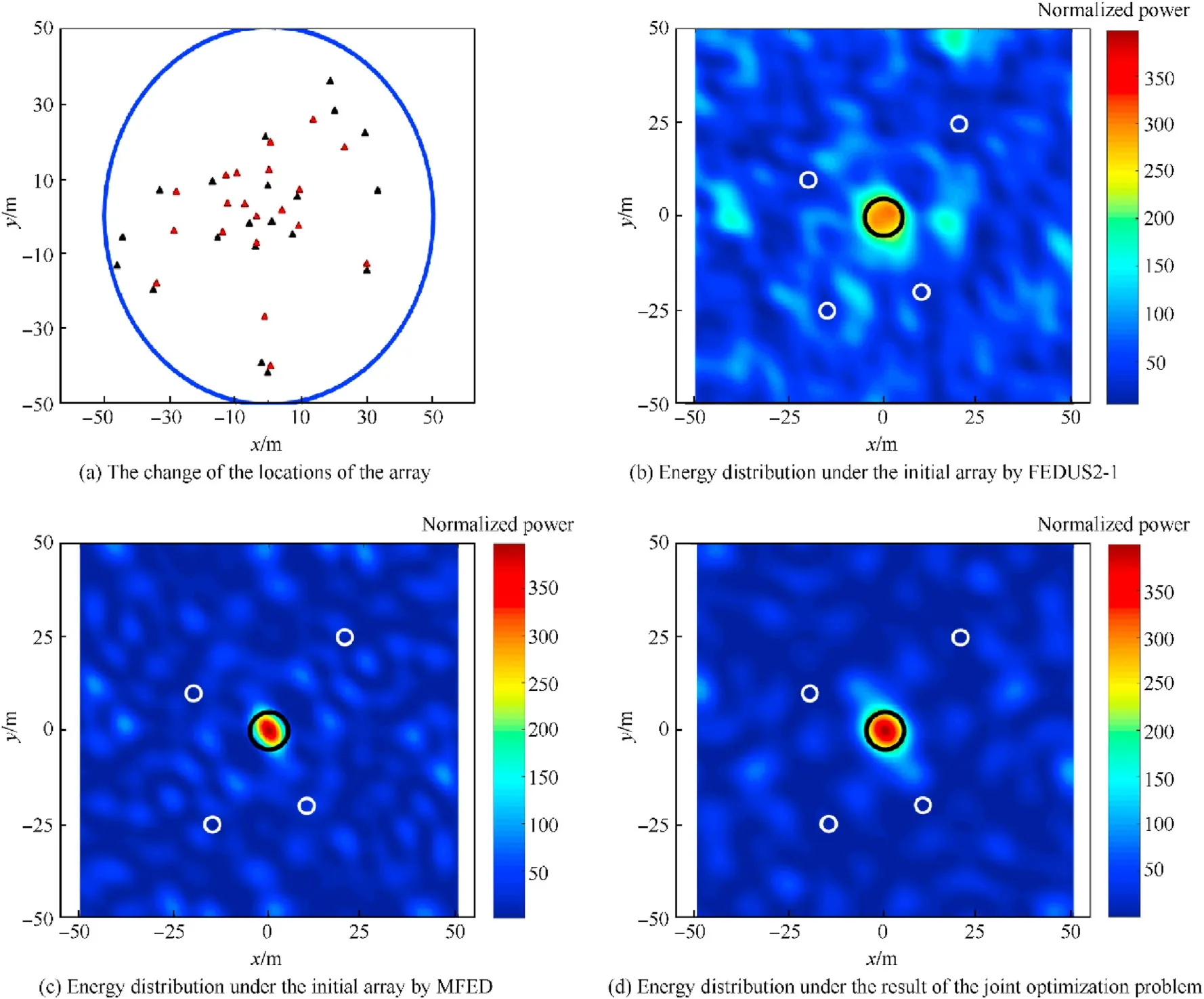
Fig. 5. The result of the joint optimization with comparison under the array consisting of M2 = 20 transmitters and constraint indexes μ2 = 20, rα = 50 m.
When the number of the transmitters increases,the constraints need to be modified to maintain a sufficient optimization room for the locations of the array.Thus,we set M=20,μ=20,M=30,and μ=16 in the next two scenarios,and increase rα to 50 m.The initial arrays are shown in Fig. 5 (a) and Fig. 6 (a) with black triangles respectively.From Fig.5(b),Fig.5(c),Fig.6(b),and Fig.6(c),the energy in some area of the target region is obviously low,where the energy cannot focus on Ωsufficiently. Meanwhile, the energy in the protected region is higher, which may cause unexpected jamming in practical. In these cases, the energy spread to the useless areas, where the grating lobe effect causes the waste of jamming resources in PREW.The result arrays are shown as the red triangles in Figs.5(a)and Fig.6(a),where the minimum distances are 3.39 m and 2.77 m respectively. We can get the energy distribution as shown in Figs.5(d)and Fig.6(d)by the joint optimization algorithm proposed.The energy in Ωis obviously increase,and the energy in the protected regions is further suppressed.
In order to further demonstrate the superiority of the model proposed than previous works, we consider a complex scenario where the state-of-the-art algorithms have poor performance. We set two target points as r=(-7m,8m,0)and r= (9m, -8m,0),and the corresponding target regions with radius r= 5m. The protected points are set as r=( -3m, - 2m,0),r= (25m, -15m, 0), r= ( - 15m, - 15m, 0), r= (10m, 15m, 0), r=(-15m,20m,0) and r= ( - 25m, 5m, 0), while the protected regions are set as the circles with the radius r= 2m. The initial array in Fig. 6 (a) is set the same with black triangles in Fig. 4 (a).
Then, we get the energy distribution as shown in Fig. 7 (b), (c)and (d). In this scenario, the target regions locate nearby the protected regions,and the energy in these regions must change rapidly in spatial. When we adopt FEDUS2-1 or MFED to design the transmitted signals merely,the energy cannot be focused onto the target regions,and the focal spots shift to the unexpected regions.Meanwhile, the energy in Ωis high because the degrees of freedom in these models are limited.When we implement the joint optimization by the algorithm proposed, the result array is shown by the red triangles in Fig.7(a).By comparing with Fig.7(b),(c)and(d), we conclude that the joint optimization algorithm has better performance in the complex scenario, where FEDUS2-1 and MFED get severer results.
To further evaluate the performance of different algorithms,we analyze some main indicators in PREW. In Table 1, we implement the joint optimization for three times in the same scenario.We set the minimum energy E, the average energy Avein Ω, and the maximum energy Eand the average energy Avein Ω. We demonstrate the superiority of the joint optimization by giving the comparison of the effective focusing ratio ηand the misfocusing ratio η, where ηand ηare defined as follows:

where Kand Kdenote the numbers of the corresponding discretized square grids,cand cdenote the intended energy levels,and I(·) is Heaviside step function. Here, we set c=60=17.8dB and c= 6 = 7.8 dB.
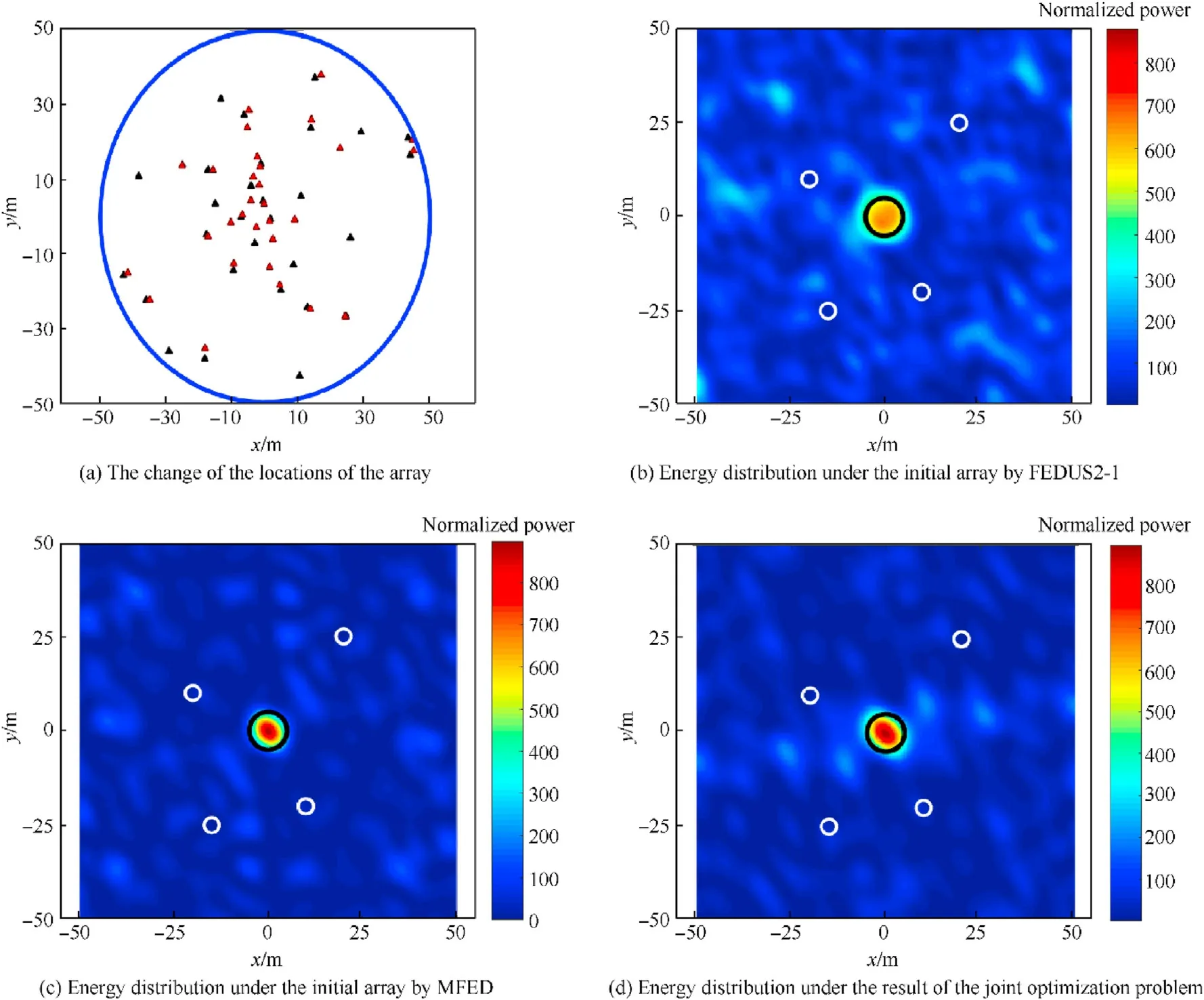
Fig. 6. The result of the joint optimization with comparison under the array consisting of M3 = 30 transmitters and constraint indexes μ3 =16, rα = 50 m.
In Table 1,it is obviously that the proposed algorithm has better performance, where O increases by 18.27% on average when compared with MFED,while ηincreases to 100%and ηdecreases to about 7% on average. We see that there are tiny differences between the indicators when we adopt the algorithm proposed for several times, because the results may be different local solutions.On one hand,the solution space has numerous saddle points,which is difficult to find the global optimal solution. On the other hand,the randomness of rand rin (11) results in the different local optimal solutions. However, these solutions get similar performance finally as shown in Table 1, and we can ignore the tiny difference of local optimal solutions.
5.2. Performance analysis
5.2.1. Comparison of different methods to solve subproblem
To compare the performance of methods to solve the subproblem, we further analyze the computational complexity and the optimal results of the subproblems, which are solved by MFED,DEM, and RTE respectively. In the experiments followed, one hundred groups of the arrays, which are set randomly, are generated for different sizes of the subproblems. We define the optimal results solved by DEM, RTE and MFED as κ, κ, and κrespectively. To compare the optimal results for convenience, we normalize the optimal values κand κby κ.
In Table 2,the optimal values listed are the average values of the subproblems, and we get the conclusion that κis consistent with κ, while κis only about 1% higher than them, which demonstrates that DEM is an accurate method and RTE is a valid method to estimate the optimal value of the UQP subproblem.Regarding the computational complexity, we use nto denote the iteration steps of the MaMi framework,while ndenotes that of the power iteration method. It can been seen that DEM and RET are both more efficient than MFED, especially when the size of M is large. The computational complexity of DEM is a little higher than RTE.Because RET is an estimation method to calculate the optimal value, which pay no attention to the accurate solution. Thus, it is reasonable to adopt two methods together in the framework for better efficiency, and without loss of accuracy at the same time.
5.2.2. The effect of threshold value on the algorithm
In the experiments shown in Figs. 4-7, we set tv=3% in the PSO-UQP framework. In order to compare the effect of different tv on the performance, we set tv as 0%, 0.5%, 1%, 2%, 3%, 4% and 5%respectively. Among them, 0% means that we adopt DEM to calculate the fitness criterion in all the iteration steps,which is the slowest but the most accurate framework. Meanwhile, we repeat 50 times for each tv to compare the performance on average.
As shown in Fig. 8 (a), gis normalized by 100% under the result of the joint optimization when tv = 0%. The algorithm convergent earlier as tv increases until tv goes up to 3%,because the method to calculate the fitness criterion is switched to RTE in some steps, which has higher speed than DEM, and the optimal result varies in a tiny scale. However, we get a bit worse performance when tv increases to 4% and 5%. Because the objective function grows too fast in the early stage of iteration,the algorithm may get wrong optimization direction by too much estimation, and the algorithm has to modify the optimization direction by DEM to get an optimal solution in the last period of the iteration,which leads to worse performance and more iteration steps.
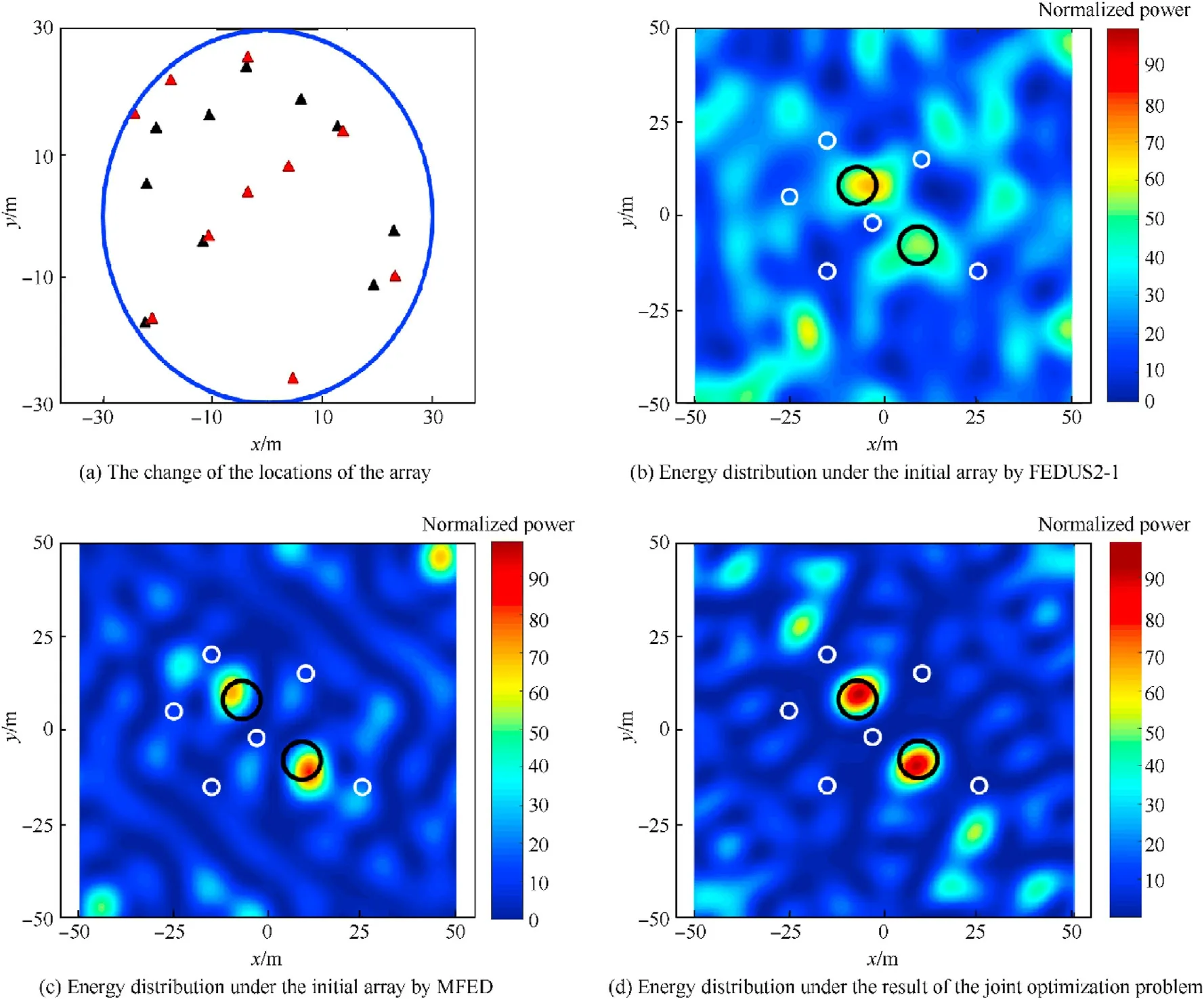
Fig. 7. The result of the joint optimization with comparison in the complex scenario.

Table 1 Performance indicators.

Table 2 The comparison of the computational complexity and results.
In Fig.8(b),the iteration steps increase with M in curves when we set different tv. Though it share the same magnitude, the algorithm convergent earlier when tv=3%.The superiority becomes more obvious when the size of the array M is large.
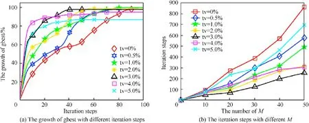
Fig. 8. Convergence performance comparison.
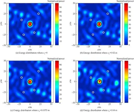
Fig. 9. Energy distribution with different localization errors.
5.3. FED with different localization errors
In this subsection, we further analyze the impact of the localization errors on the performance, and we demonstrate the correctness of the result derived. For comparison, the localization errors are set as ε=0,ε=0.02m <λ/8,ε=0.0375m=λ/8 and ε=0.04m >λ/8 respectively, where λ = c/f= 0.3m. In these scenarios, the true locations of the transmitters are in a spherical surface randomly, where the centers of the spheres locate at the corresponding transmitters as shown in Fig.3(a),and the radiuses are the localization errors set above. The transmitted signals are still designed under the ideal locations of the array as shown in Fig. 3 (a).
As shown in Fig. 9 (a), the localization error is set as 0, which means that the locations of the true array are the same with that of the ideal one, and the transmitted signals are matched with thearray. Thus, we can get three conclusions by comparing the simulation results above. First, there is almost no variation when the localization errors are less than λ/8. However, the energy distribution varies a lot when the localization errors rise up to λ/ 8. By comparing Fig. 9 (c) and (d), we can verify the correctness of maximum localization error derived,because εis only 6.67%larger than λ/8 while the energy distribution varies a lot. Second, the focused energy spread to other regions when the localization errors exist, which leads to the energy level increasing in other regions.Third, the focal spots shift within an acceptable range, though the localization errors exceed λ/8, because we extend intended points to the corresponding regions and then discretize the regions into various points,which counteracts the impact of localization errors to some extent.

Table 3 Indicators comparison under the array with localization errors.
In Table 3, we further analyze the performance when different localization errors exist. We can find that the performance varies implicitly when ε ≤λ/8. However, it is worth noting that the performance deteriorate when the localization errors increase up to 0.04 m. Aveis close to c, which leads to the focusing rate ηdecreasing severely. Meanwhile, Eincreases by 62.51%, and the corresponding point has an unexpectedly high energy level.Though we consider the errors in the model by discretizing the regions into points,the robustness is limited when the localization errors exceed the maximum localization errors, which also demonstrates the importance of the conclusion derived.
6. Conclusions
In this paper, we propose a joint optimization model and the corresponding algorithm for the locations of the array and the transmitted signals,and we derive the maximum localization error that FED can tolerate. We improve the performance by increasing the degree of freedom in the model substantially compared to state-of-the-art methods. A PSO-UQP framework is established to solve the joint optimization problem, where PSO is employed to optimize the locations of the array, and designing the transmitted signals is considered as a UQP subproblem to calculate the fitness criterion. Meanwhile, two methods are presented for the UQP subproblem, where RTE estimates the fitness criterion with more efficiency,and DEM solves the subproblem with more accuracy.We set a threshold value to determine which method to adopt in the PSO-UQP framework to accelerate the algorithm. Then, the maximum localization error is derived under some reasonable assumptions, and we conclude that the localization errors should be less than λ/8.The simulation results indicate the effectiveness and the necessity of the proposed algorithm, especially in complex scenarios. By analyzing the impact of different localization errors,we also demonstrate the correctness of the maximum localization error derived. In the future, we will further study the analytical algorithms and design the robustness transmitted signals to promote the overall performance.
Anhui Provincial Natural Science Foundation(Project for Youth:1908085QF252). Research Program of National University of Defense Technology (ZK19-10).
We declare that we have no financial and personal relationships with other people or organizations that can inappropriately influence our work,there is no professional or other personal interest of any nature or kind in any product, service and/or company that could be construed as influencing the position presented in,or the review of,the manuscript entitled,“A Joint Optimization Algorithm for Focused Energy Delivery in Precision Electronic Warfare”.
杂志排行
Defence Technology的其它文章
- Blast response of clay brick masonry unit walls unreinforced and reinforced with polyurea elastomer
- Adaptive robust feedback control of moving target tracking for all -Electrical tank with uncertainty
- Effects of phase change material (PCM)-based nanocomposite additives on thermal decomposition and burning characteristic of high energy propellants containing RDX
- A novel feature extraction method for ship-radiated noise
- Mechanical properties of thermal aged HTPB composite solid propellant under confining pressure
- An optimized run-length based algorithm for sparse remote sensing image labeling
