基于锥形七芯光纤的紧凑型超声波传感器
2022-04-01杨熙阴欢欢邵志华乔学光
杨熙,阴欢欢,邵志华,乔学光
(西北大学物理学院,西安710069)
0 Introduction
Traditional detection approaches usually employ the Piezoelectric Transducers(PZTs)as the signal source and receiver[1].However,these current-driven transducers have some inherent drawbacks(susceptibility to electromagnetic interference,narrow response frequency band and not resistant to high temperature).Fiberoptic sensors have attracted significant attention in ultrasonic detecting due to their outstanding advantages,such as:anti-electromagnetic interference,small size,easy reuse and bandwidth of response frequency[2].
The majority of fiber-optic ultrasonic sensors are based on Fiber Bragg Gratings(FBGs)[3]and Fabry-Pérot interferometers(FPIs)[4-5].FBG′s response sensitivity to Ultrasonic Waves(UWs)is determined by reflectivity and spectral bandwidth,when using the spectral filtering technology.LI Yuan et al.proposed an allfiber multi-channel ultrasonic sensor by using a switchable FBGs filter in an Erbium-Doped Fiber Laser(EDFL).UWs could be detected by monitoring the laser intensity modulation via the ultrasound-induced relative spectral shift of the matched FBGs in the filter[6].However,the response frequency range of ultrasonic sensors based on FBG is relatively narrow.In addition,FPI sensors are also capable of detecting UWs with high sensitivities.FPI ultrasonic sensors generally consist of a diaphragm and a fiber-optic end-face as two reflectors.The diaphragm materials include polymer,metal films and graphene films,etc.[7-10].For example,GUO Fanwen et al.proposed a fiber-tip sensor using an ultra-thin silver diaphragm for high-sensitivity and high-frequency ultrasonic detection.The sensor has a 300 nm thick diaphragm on a tube with an inner diameter of 75 μm[11].The static pressure sensitivity is measured to be 1.6 nm/kPa,and the lowest order resonant frequency is measured to be 1.44 MHz[11].However,the complex preparation of diaphragm materials,poor chemical stability and heat resistance limit the sensor′s application.In comparison,the inter-mode interference sensors based on Tapered Seven-core Fibers(TSCFs)can be another remarkable candidate for UW detection.The ultrasonic response of the sensor is improved by tapering the sensing fiber.
In this paper,a compact fiber-optic ultrasonic sensor based on TSCFs is proposed and experimentally demonstrated.The tapered region of TSCFs has a strong evanescent field effect,which largely overlaps with the ultrasonic coupling agent(water).The applied ultrasonic field changes the water density and then shifts the interferometric fringe of the transmission spectrum.Herein TSCFs in different diameters are fabricated,and their mode interferences and ultrasonic measurements are comparatively analyzed.
1 Sensor fabrication and principle
The sensor comprises a TSCF sandwiched between two Single-Mode Fibers(SMFs),forming a cascade structure of SMF-TSCF-SMF,as shown in Fig.1(a).Fig.1(b)shows the waist micrographs of TSCFs with different diameters.In the SMF-TSCF-SMF structure,high order modes are easily excited due to the core mismatch of SMF and Seven-Core Fiber(SCF).Excited multiple modes continue to propagate along the TSCF and then arrive at the tapered region.Due to the sharply reduced taper diameter(as thin as several micrometers) ,the core distances are largely decreased and the evanescent fields are extended simultaneously[12-13].Thus,it is sufficient to induce diverse inter-modal coupling at the abrupt taper,including the mode coupling among cores,and coupling and recoupling of the cladding-to-core modes.Finally,most of these fiber modes are coupled back to the SMF,and highly sensitive mode interferences are obtained[14].

Fig.1 The proposed TSCF sensor
A commercial fiber fusion machine(Fujikura,FSM-80C)is used to fabricate the SMF-TSCF-SMF structure with a 9-mm-long seven-core fiber.Then a fiber flame taper(FBT-Zolix)is used to taper the SCF into TSCF in different diameters.A certain prestress is applied to keep the SCF tight and straight during the fused tapering process.To obtain a uniform and symmetrical TSCF,the tapering step is divided into two steps:setting the velocity and displacement of sliders to 2.6 mm/s and 0.5 mm,respectively,and then increasing the two drawing parameters to 3.6 mm/s and 2.5 mm separately.The tapering parameters can be adjusted as needed to fabricate TSCFs in different diameters.In this paper,SCF(YOFC,MC1010-A,China)is used to make ultrasonic sensors.The six cores of the seven-core fiber are located on the six corners of the regular hexagon,and the center of the hexagon is the middle core of the seven-core fiber.The diameter of the SCF is 150 μm,and the distance between adjacent cores is 42 μm.Taper fibers are fabricated with diameters of 11 μm,19 μm and 29 μm,and the micrographs of the tapered areas are shown in Fig.1(b).
Fig.2 shows the transmission spectra of the SMF-TSCF-SMF structure with taper diameters of 29 μm(black curve),19 μm(red curve)and 11 μm(blue curve).Owing to the core mismatch at the lead-in junction,the core-guided fundamental mode from the lead-in SMF is coupled into the cladding and core of the TSCF.According to the inter-mode interference mechanism,when the diameter of TSCF fiber is 29 μm,these excited modes propagate in the cladding and core respectively and finally couple back to the lead-out SMF together with weak core modes.No obvious modal interference is observed in the transmission spectrum of the SMF-SCFSMF structure(black curve).When the SCF is tapered to be below 20 μm,the closer fiber cores and expanded mode fields enhance the mode excitation and coupling in the TSCF,leading to the typical multi-mode interference in Fig.2(red and blue curves).Thus,TSCFs with diameters of 11 μm and 19 μm are typically used in subsequent experiments.
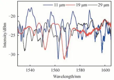
Fig.2 Transmission spectra of the SMF-TSCF-SMF structure with 29 μm diameter taper,19 μm diameter taper and 11 μm diameter taper
The transmission spectra of TSCF with diameters of 11 μm and 19 μm in water and air are shown in Fig.3 As can be seen,the spectra of TSCF before and after water entry change greatly when the diameter of TSCF taper is too small.Therefore,a tapered optical fiber with a diameter of about 19 μm is used as the ultrasonic receiver in this experiment.High order modes are more easily excited because of the taper structure of SCF.As the taper diameter decreases,the transverse modes of the input light expands and couples with the cladding modes.According to the coupled-mode theory[14],the coupling coefficient(K)within the TSCF can be expressed as

Fig.3 Transmission spectra of TSCF with different diameters before and after entering water

whereais one core diameter,λis the optical wavelength in vacuum,ncoandnclare the effective Refractive Index(RI)of the core and the cladding modes,respectively.k0andk1represent the modified Bessel functions of the second kind.βpis the propagation constant.It is clear that the modal excitation and coupling in Figs.2(a)and(b)largely depend on the taper diameter of the TSCF(proportional to core diametera).The coupling between TSCF cores increases with the decrease of core distance.
On the other hand,the core and cladding diameters in the tapering region become thinner due to the tapering.The light in core can be transmitted along with the surface of the tapered SCF due to the evanescent wave[15].When the TSCF is immersed into water,the fundamental guided mode of the microfiber partially spread into the water in the form of evanescent field.The transverse mode field and the corresponding effective indexneffcan be changed by varying the RI or density of water,based on the evanescent field interaction.Considering the applied acoustic pressure is weak,the RI of water change can be approximately condemned as linear.Through the firstorder Taylor′s expansion,the relation between the RI and the acoustic pressure can be given by[16,17]

wherepis the applied acoustic pressure,p0=100 kPa,k=1.5×10⁻¹⁰Pa-1,nw,0=1.33 is the RI of water at static condition.Due to the axial constraints,the axial elongation of the fiber is zero.Therefore,only the index change contributes to the phase change[18].As the optical signal enters TSCF,multiple modes are excited and coupled.The transmission spectrum of TSCF is the superposition of multiple modes,and the mode field distribution after a propagation length ofLin TSCF can be given by[18]

whereψm(r),cmare the mode field profile,excitation coefficient,and the propagation constant of each mode in TSCF the mode number in TSCF,respectively.Mis the mode number in TSCF.Therefore,the change of effective RI of the transmission mode will cause the output intensity of the sensor change.In addition,it has been demonstrated in Refs.[19,20]that theneffwithin the TSCF changes with the external RI.Therefore,the liquid RI(nw(p))change around the sensor finally results in variation of the output optical intensity.
2 Experimental results and discussions
The fiber-optic ultrasonic detection system is shown in Fig.4.A tunable laser(Santec,TSL-710)with a 100 kHz linewidth as the light source is launched into the sensor through a fiber.The light power is converted into an electrical signal by a photodetector(PD,New Focus)with a bandwidth of 10 MHz and finally monitored by an oscilloscope(RIGOL,DS2302A).The function generator(OLYMPUS,5077R)generates a rectangular pulse signal with amplitude of 4 V and repetition frequency of 100Hz to drive the PZT(EasyNDT,0.5P25SJ,SIUI,1Z20SJ50DJ,EasyNDT,5P20SJ).The response characteristics of TSCF to UWs are tested.Experiments are carried out in water for better ultrasonic propagation and coupling.Edge band filtering method is used to demodulate the ultrasonic signal received by TSCF sensor.
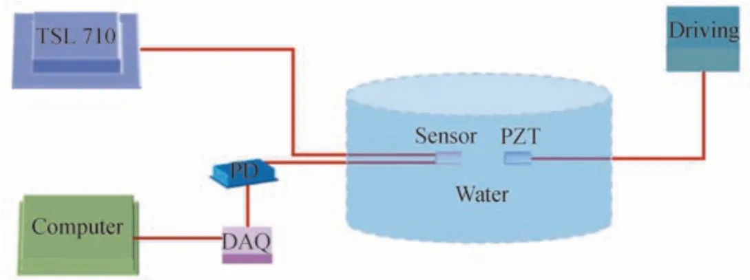
Fig.4 Schematic diagram of the ultrasonic detection system
As expected,the continuous UW signal presents good uniform and stability in time domain,as shown in Fig.5(a),where the frequency of PZT is 1 MHz and the amplitude is 4 V,the output power of the tunable laser is 20 mW and the distance between the sensor and PZT is 2.5 cm.Fig.5(b)shows the time domain response of the TSCF to the UW single.The response amplitude of the TSCF sensor is of about 0.43 V.

Fig.5 1 MHz sensor ultrasonic response
To demonstrate the stability of the sensor,the repetition frequency of the signal generator is fixed at 100 Hz and the driving amplitude is 4 V to drive PZT to emit ultrasonic with a frequency of 1MHz.The TSCF sensor response sequence is collected at room temperature,as shown in Fig.6(a).The corresponding fluctuations of peak voltages of sensor response signal are shown in Fig.6(b).The maximum fluctuation of the output voltage is only 0.004 V.Compare with the signal voltage(about 0.224 V),the fluctuation can be neglected.Therefore,the uniform pulse array confirms the sensing stability.The stability and accuracy of wave length and high power of TSL-710 ensure the good stability of the sensing system and the high sensitivity detection of UWs.
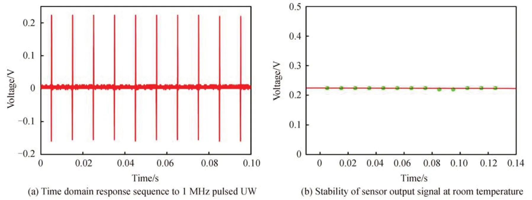
Fig.6 Sensor stability test
The response to UW of sensor is performed at the different distances between PZT and sensor.In the experiment,two devices are hold in the same axis,and the sensor is moved along the axis by moving stage.UWs are recorded in the range of 1 cm to 5 cm with a separation of 0.5 cm.As shown in Fig.7(a),the voltage is 0.43 V when distance between the sensor and the PZT is 3 cm.The voltage signal changes with the distance change between PZT and the sensor as shown in Fig.7(b),which increases at first and then decreases.The main reason is that the PZT used in the experiment is a focused emission source with a focal length of 3 cm.The UW focuses on the sensor when the distance between PZT and sensor is the PZT focal length,and the sensor receives the maximum ultrasonic energy.When the distance between sensor and PZT is not equal to the focal length of PZT,the UW energy received by the sensor is greatly reduced.
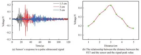
Fig.7 Experimental measurement
The sensor also measures UWs at several frequencies of 250 kHz and 5 MHz,and the results are shown in Fig.8.These experimental results show that the sensor has good ability to measure broadband UWs.Fourier transform is used to convert the time domain signal of the sensor into spectrum information.As shown in Fig.9,the main frequencies of 500 kHz and 5 MHz are consistent with the actual PZT transmission frequency.
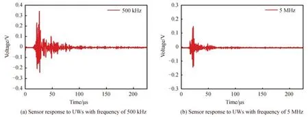
Fig.8 Ultrasonic response of sensor
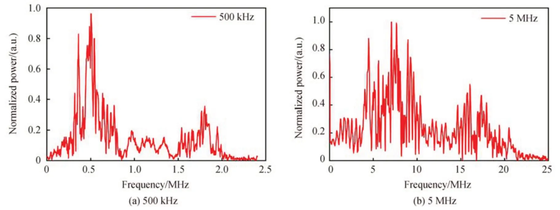
Fig.9 Spectrum response characteristics of sensor to pulsed UWs with frequency of 500 kHz and 5 MHz
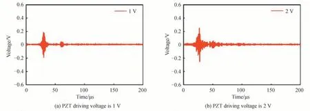
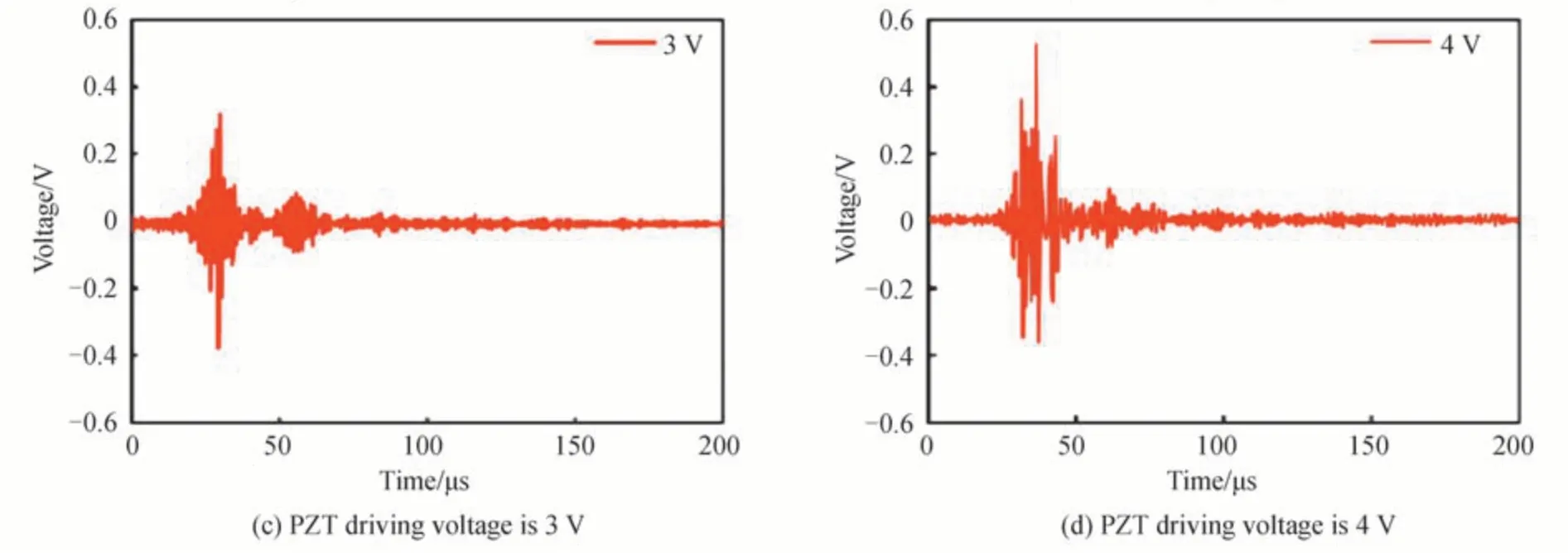
Fig.10 Variation of sensor response amplitude with ultrasonic intensity
The change of sensor time domain signal with PZT driving voltage is shown in the Figs.10.PZT voltage gradually increases from 1 V to 4 V,and the amplitude of ultrasonic signal received by the sensor is also gradually increasing.
3 Conclusion
In conclusion,a compact fiber-optic taper sensor based on Tapered Seven-Core Fiber(TSCF)is designed for high frequency Ultrasonic Wave(UW)detection.Due to the tapered region of TSCFs has a strong evanescent field effect,when placing the sensor in water,the UW signal periodically changes the refractive index of the surrounding liquid and modulates the transmission spectrum according to the evanescent-field interaction between the liquid and the transmitting light.The TSCF with different diameter is analyzed theoretically,and the TSCF with region diameter of 19 μm is selected for experimental test.By testing the response of the TSCF to ultrasonic signals with different frequencies and intensities,it is proved that the sensor has good ultrasonic response characteristics.