Performance analysis and design of loitering munitions:A comprehensive technical survey of recent developments
2022-03-29MarkVoskuijl
Mark Voskuijl
Faculty of Military Sciences,Netherlands Defence Academy,Den Helder,The Netherlands
Keywords:Loitering munition Unmanned aerial vehicle Flight performance Design
ABSTRACT Loitering munitions are increasingly used in armed con flicts.An extensive database of loitering munitions is developed based on information available in the public domain.This database includes dimensions,weights,and performance parameters such as flight endurance and communication range.Based upon this dataset,6 categories of loitering munitions are identi fied and statistical trends in the form of equations are provided for each category.The statistical trends are supported by aircraft performance theory tailored to loitering munitions applications.Altogether,the combination of the database,statistical trends and aircraft performance theory can be used to analyse the flight performance and design considerations of new loitering munitions of which only limited non-technical information is available in the public domain such as pictures and news articles.Based on the statistical trends and aircraft performance theory it is concluded that for long range applications,the preferred design solution is the conventional con figuration.The cruciform con figuration is bene ficial in case precision flight path control is of prime importance.The tandem wing con figuration combines the bene fits of a canister launch and relatively high aspect ratio wings suitable for long range flight.Finally,the delta wing design provides a large internal volume and a high terminal attack airspeed.Two example case studies are included to illustrate the flight performance capabilities of two types of loitering munitions used in the current con flict in Yemen(a long range conventional design and a delta wing con figuration).
1.Introduction
At a relatively low cost,unmanned aerial systems equipped with a warhead can be used nowadays to target amongst others,tanks,military vehicles and military personnel.This development is rapidly changing the battle field and allows countries with limited funding and non-state actors to purchase off the shelf air power[1].Weaponized kamikaze drones have been used with frequent success in the recent Nagorno-Karabakh con flict between Armenia and Azerbaijan.Egozie has appropriately designated this con flict as the first loitering weapon systems war[2].This development can also be observed in the present con flict in Yemen.Ansar Allah,the Houthi rebel movement has for example used long range unmanned aerial systems in combination with land cruise missiles to target oil re fineries in Saudi Arabia[3].The weaponized kamikaze drones or unmanned aerial systems equipped with a warhead described above are designated in this research article as loitering munitions.These unmanned aerial vehicles are intended to detonate on impact with their target much like a traditional air to ground missile.Consequently,the loitering munitions are not intended for single use and not to be recovered.The de finition by the UK Ministry of Defence is used to classify loitering munitions in order to make a clear distinction with cruise missiles,precision guided munitions and unmanned combat aerial vehicles:
“Loitering munitions are low-cost guided precision munitions that can be maintained in a holding pattern in the air for a certain time and rapidly attack land or sea non-line-of-sight targets.Loitering munitions are under the control of an operator who sees a real-time image of the target and its surrounding area,giving the capacity to control the exact time,attitude,and direction of the attack of a static,relocatable,or moving target,including providing a contribution to the formal target identi fication and con firmation process”[4].
The first loitering munitions such as the Israeli Aerospace Industries Harpy intended for suppression of enemy air defences,were developed in the 1990s.At present however,many different designs are being marketed[5].The different types of loitering munitions currently used worldwide(listed in Appendix B)can be divided based on their con figuration into six main categories:
·Conventional fixed-wing
·Canard
·Delta wing
·Cruciform wing
·Tandem wing
·Rotorcraft
One should realize that in the(near)future other con figurations may be developed which would require an extension of this list.Furthermore,designs which fit in multiple categories are also a possibility.For example,one could think of a fixed-wing design with dedicated rotors for a hover and vertical take-off capability.
In terms of the propulsion system,nearly all loitering munitions use propellers or rotors to provide thrust.The power is typically provided by either an electric engine or a gasoline engine.Nearly all fixed-wing designs have a single pusher propeller.
The loitering munitions covered in the present research are used for a variety of targets.They are employed for anti-personnel,antiarmour,anti-structure and suppression of enemy air defences applications.The speci fic application determines the required type and size of the warhead.Rotary wing loitering munitions are a special category which are used for urban combat.Apart from the type of target,the mission is characterized by the required loitering time(endurance)and the distance of the target(range).
Literature in the engineering sciences on the topic of loitering munitions is primarily focused on guidance,navigation and control aspects including target recognition and swarming techniques.Accurate flight path control under real world conditions such as wind and turbulence is of prime importance for loitering munitions.This topic is addressed by Refs.[6,7].Besides the ability to follow a prescribed flight path with high accuracy it is also key for mission success to select an effective flight path and to identify ground targets.Optimal path planning strategies for loitering munitions are described in Ref.[8].Wang et al.[9,10]investigated precise ground target localization using a video camera as sensor for loitering munition applications.On a higher level,collaboration aspects between multiple loitering munitions must be addressed.Research on swarming technologies for loitering munitions can be found in Ref.[11].
A limited number of research articles investigate design aspects of subsystems of loitering munitions or speci fic vehicles.Liu et al.[12]focus on fuse warhead coordination for loitering munitions.The aerodynamic characteristics of a speci fic loitering munition design were investigated in Ref.[13].Research on the aerodynamic design of gun-launched loitering munitions was presented in Ref.[14].A design method for electric propulsion systems for small loitering munitions is presented in Ref.[15].A broader perspective on propulsion systems for loitering munitions is provided in Ref.[16].
There appears to be no scienti fic literature in the field of engineering that addresses overall con figuration design and flight performance aspects of loitering munitions.The primary aim of this research article is therefore to provide a comprehensive technical overview of current loitering munitions from a design and aircraft performance perspective.For this purpose,an extensive database of loitering munitions is developed based on information available in the public domain.This database includes dimensions,weights,and performance parameters such as flight endurance and communication range.Con figuration design aspects such as the type of propulsion system,the launch method and the planform are also included.Based upon this dataset,statistical trends are provided for different categories of loitering munitions.The statistical trends are supported by aircraft performance theory tailored to loitering munitions applications.Altogether,the combination of a database,statistical trends and aircraft performance theory can be used to analyse the flight performance and design considerations of loitering munitions of which only limited non-technical information is available in the public domain such as pictures and news articles.
This article is structured as follows.In section 2,the relationship between design criteria for loitering munitions and aircraft performance theory is established.A detailed theoretical background of the aircraft performance theory used is given in Appendix A.Sizing correlations and statistical trends are presented in section 3.These sizing correlations are based upon the loitering munitions database which is provided in Appendix B.Two example case studies are presented in Section 4.The first case study addresses the flight performance of a long range fixed-wing loitering munition with a conventional con figuration(high aspect ratio wing and conventional empennage)used in the Yemen con flict.The second case study is dedicated to a relatively new loitering munition with a delta wing design.Finally,conclusions and recommendations will be made.
2.Aircraft performance and design criteria
In this section,five high level performance and design criteria are addressed from a theoretical perspective.The total flight time capability of a loitering munition(endurance)is treated first.Next the terminal dive attack airspeed is discussed.The ability to achieve precision control of a trajectory in the presence of external disturbances is the third performance criteria.This ability is also directly related to the inherent controllability of the loitering munition which in turn depends on its con figuration.The other two criteria addressed are the ability to perform hovering flight,relevant for urban warfare and the size needed for the launch system.In the final paragraph,a summary is given of the performance and design criteria in relation to the aircraft con figuration and its design parameters.
2.1.Loitering endurance
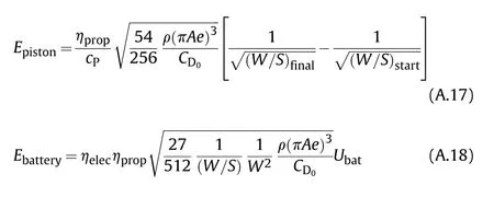
If a flight is conducted at a constant(optimal)angle of attack and a constant altitude,endurance can be calculated with Eqs.(1)and(2).To arrive at these equations it is assumed that the power speci fic fuel consumption and the propeller ef ficiency are constant over the range of flight speeds of interest.For a detailed derivation of these equations,the reader is referred to Appendix A.1.
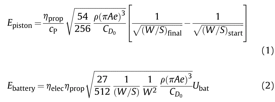
These equations demonstrate which design parameters are of importance for loitering endurance(E).The propulsion system should have a low power speci fic fuel consumption(c)or energy consumption(η)and a high propeller ef ficiency(η)at the airspeed at which the aircraft loiters.The aspect ratio(A)and Ostwald factor(e)are important aerodynamic design parameters.Furthermore,low altitude flights lead to longer endurance.The zero lift drag coef ficient(C)should be as small as possible.Finally,a low wing loading de fined as aircraft weight divided by wing surface area(W/S)and a large fuel fraction(ratio of fuel weight over maximum take-off weight)are design parameters in case of aircraft equipped with internal combustion engines.For electrically powered aircraft the wing loading and the aircraft weight should be as low as possible.A large amount of electric energy(U)is evidently also bene ficial.However,the energy stored in the batteries has a direct relation to the aircraft weight even though these parameters appear separate in the equation.Some loitering munitions offer the possibility to use either a small or large warhead.With a smaller lightweight warhead,endurance is improved.In short,a conventional aircraft con figuration with a long slender wing and a lightweight design is most suitable to achieve good loitering endurance performance.In addition,an ef ficient propulsion system is needed.Finally,a relatively low airspeed is required during loitering and an appropriate size warhead should be selected.
2.2.Terminal attack dive airspeed
The maximum airspeed(V)of a loitering munition in a terminal attack dive is de fined by Eq.(3).


For shallow descent angles,the time rate of change of potential energy is small and the power required to overcome the zero lift drag is an order of magnitude larger than the power required to overcome the lift induced drag.For steep descent angles,the time rate of change of potential energy becomes an important factor.Hence,it can be concluded that the parameters in the lift-induced drag term have little effect on the maximum airspeed in a terminal attack dive.For signi ficant descent angles it is even helpful to have a large aircraft weight.
2.3.Precision trajectory control
It is of key importance to the design of a loitering munition that the flight trajectory can be controlled precisely,especially in the final phase of the flight.In this phase,atmospheric disturbances such as gusts and turbulence can be encountered.In addition,the target may be moving dynamically.
2.3.1.Atmospheric disturbances
If an aircraft encounter a gust,it will experience an increase in the load factor.As a result it will deviate from its flight path.The load factor increase(Δn)due to a vertical gust with a velocity(U)can be represented with the next equation.

A derivation of this equation is presented in appendix A.3.Thus,the main design parameters that in fluence the sensitivity of an aircraft to a gust are the wing loading(W/S)and the lift curve slope(d C/dα).A high wing loading and a low value of the lift curve slope are bene ficial for the gust sensitivity.In addition,operational parameters such as the airspeed and the flight altitude also have an in fluence.The factor K is related amongst others to the shape of the gust and the length in relation to the vehicle size.The equation demonstrates that the change in load factor due to a gust increases with airspeed.The delta wing con figuration is known to have a small lift curve slope compared to other con figurations.A delta wing is known to be structurally ef ficient and provides a large internal volume for a payload.In case the wing loading of a delta wing is similar to other con figurations,it is least susceptible to external disturbances.
2.3.2.Agility and controllability
Aircraft with a conventional con figuration exhibit what is called non-minimum phase behaviour when changes in the flight path angle are made[17].When a horizontal flight path is flown,a down force on the tail must be created in order to rotate the aircraft noseup.Once the aircraft has rotated,the lift will increase and the flight path angle will increase.However,initially the aircraft will have a small downward motion due to the down-force on the tail plane.If the pitch control surface is located ahead of the centre of gravity,such as with the canard con figuration,the non-minimum phase behaviour will not be present and the aircraft can respond quicker to control inputs.If primary pitch control surfaces are located close to the centre of gravity,these can be used to directly control the lift force without causing signi ficant rotational motion.Direct lift control allows for an even faster response to desired changes in the flight path angle[18-20].The cruciform con figuration makes it possible to introduce direct a side force control.From a controllability perspective,the cruciform con figuration is the preferred solution followed by the canard and tandem con figurations.There are signi ficant challenges with respect to the directional stability and control of the delta wing con figuration since it does not feature a conventional vertical tail and rudder[21,22].In some designs vertical tails are added to the wing tips.These tails however have a relatively small moment arm with respect to the centre of gravity and also a relatively small area.Altogether,this leads to a small tail volume.For directional control,drag rudders at the wing tips can be used.This approach has been applied amongst others on the B-2 stealth bomber[22].Finally,in case different size warheads are possible on a speci fic design,the selection will impact the weight and balance and thereby the manoeuvrability.
2.4.Size of launch system
There are various methods to launch loitering munitions.The launch method for each loitering munition analysed in the present research is provided in Appendix B.1.The smallest unmanned aerial vehicles which weigh only a few kilograms can be launched by hand.A more common approach is to use a launch rail.Launch rails for small loitering munitions can be carried and set-up manually.In case the loitering munition is large,a mobile launch rail can be constructed or it can be placed on the back a vehicle or a maritime platform.The disadvantage of using a launch rail is the large volume it requires.If loitering munitions can be folded,they can be stored in what is called a canister.Since these canisters have a relatively small volume,multiple canisters can be placed on a single ground vehicle,maritime platform or even aircraft or helicopter.A small loitering munition stored in a canister can also be carried as a backpack by a soldier.An example is the Hero-30 loitering munition which is stored in a canister fromwhich it is launched by means of a pneumatic system[23].The capability to transport and launch multiple loitering munitions from a single vehicle is obviously very advantageous from an operational perspective.However,it does have a major impact on the design of the loitering munition since it needs to fit inside a canister.Besides the methods mentioned above,there are some alternative methods to launch loitering munitions.For example,the Burevestnik-MB for example can be stored under the wing of an aircraft[24,25],much like an air to air missile whereas the Defendtex Drone-40 is launched by a grenade launcher[26].Finally,rotary wing loitering munitions are capable of vertical take-off and landing and do not require a special launch mechanism.Pictures of commonly used approaches are presented in Fig.1.
2.5.Summary of design criteria
In the previous paragraphs it is explained how aircraft design parameters in fluence performance criteria relevant for loitering munitions.The relations between design parameters and performance criteria are summarized in Table 1.
It can be observed from Table 1 that various performance criteria are con flicting.A conventional design is likely the best solution if only loitering endurance is considered.However,a conventional con figuration with a high aspect ratio wing is dif ficult to fold into a canister for launch.In case both these requirements are important,an intermediate solution such as a tandem wing may be the best compromise.A design with a canard will also performwell in terms of loitering endurance but probably not as good as a conventional con figuration.On the other hand,in terms of manoeuvrability,a canard will outperform a conventional con figuration.A delta wing design has a relatively high wing loading and is therefore less susceptible to external disturbances such as gusts when symmetric(longitudinal)motions are considered.Furthermore,the internal volume is relatively large and allows for a large warhead as payload.This in turn,combined with a low wetted area allows for a high terminal attack speed.The directional control of the delta wing con figuration remains a signi ficant challenge.The cruciform con figuration is especially suitable for precision control.For such a con figuration it is a logical design solution to fold the wings.Finally,for special applications such as urban warfare it may be useful to have a design with hover capability.In that scenario a rotorcraft is the preferred con figuration.Primary disadvantages of rotorcraft are a low endurance and limited maximum airspeed compared to fixed-wing designs.

Table 1 Summary of performance criteria,design requirements and suitable con figurations.
There are of course many more aircraft design requirements that play a role in the selection of a con figuration for the design of a loitering munition.The discussion above is merely intended to provide insight in the main(con flicting)requirements and possible design solutions.In the next section,sizing correlations of loitering munitions are provided.The observations and conclusions made in the current section will help to understand these sizing correlations.
3.Sizing correlations
An extensive literature study was conducted in order to compare the characteristics of different loitering munitions.This study has resulted in a loitering munitions database which is provided in Appendix B.The database consists of 52 loitering munition designs which are manufactured in 16 different countries.The largest designs can deliver warheads up to 30 kg and have an endurance in the order of 10 h.The smallest designs on the other hand,have a flight endurance of only 10 min and a grenade size warhead.Key performance and design parameters such as endurance,weight and dimensions,are summarized in several figures.The correlations between maximum take-off mass,endurance and warhead mass are presented in Fig.2,Fig.3 and Fig.4 respectively.
It can be observed in Fig.2 that the preferred con figurations for a large warhead mass(in excess of 10 kg)are the conventional-,the delta wing-and the canard con figuration.A large warhead mass requires a relatively large aircraft in terms of dimensions and weight.Hence,the requirement for a large warhead mass does not go well with a requirement for a canister launch.These three con figurations are inherently not suitable to be folded in a canister.A delta wing design has a relatively large internal volume for a given wing area.This makes it possible to store a large warhead inside.The conventional and canard con figuration can have a large wing span and therefore a high aspect ratio.This makes them naturally suitable for long range or high endurance missions.Hence,the same trend is observed in Fig.3.Furthermore,one can expect that the requirement of a large warhead mass is combined with the requirement for a long endurance.
The sizing correlations in Figs.2 and 3 include trend lines.These trend lines are de fined as power laws as is common in the field of preliminary aircraft design[27,28].The power laws are obtained by linear regression(least squares fit)of the logarithmic transformation of the data.This approach is described in detail by Verstraete et al.[29]who performed sizing correlations for all types of fixed-wing unmanned aerial vehicles.The power laws can be written as follows(Eq.(5)and Eq.(6)).

Fig.1.Three examples of common launch methods for loitering munitions.Left:Fire shadow loitering munition launched by rail(image by Think Defence),middle:Hero-30 loitering munition which uses a canister launch method(image by Reise Reise),right:mobile launcher of multiple Chien hsiang loitering munitions(image by Kenchen 945).
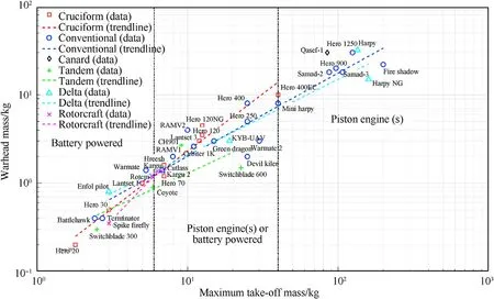
Fig.2.Relation between warhead mass and maximum take-off mass for different categories of loitering munitions.
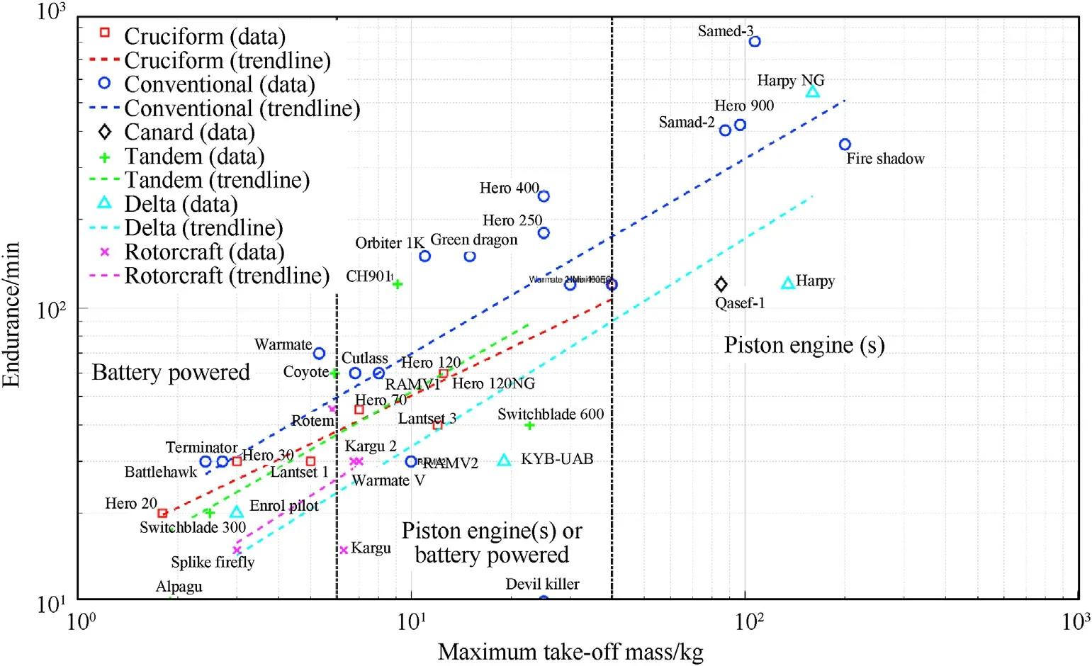
Fig.3.Relation between endurance and maximum take-off mass for different categories of loitering munitions.
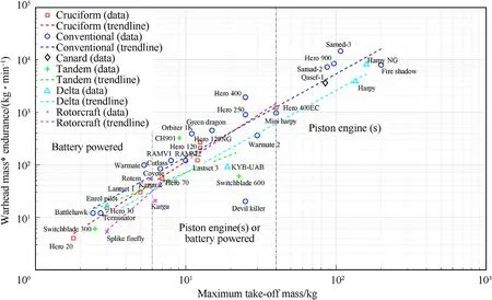
Fig.4.Product of warhead mass and endurance versus maximum take-off mass for different categories of loitering munitions.

The coef ficients A,B,C and D in the power laws are provided in Table 2 for each category of loitering munitions.Also included in the table is the number of data points(N)based on which the regression is performed and a measure of the goodness of the linear fit(R).
Figs.2-4 also indicates whether the loitering munitions are powered by batteries and electric motors or gasoline and piston engines.Below 6 kg,all designs have a battery electric propulsion system.The use of a battery-electric propulsion system has an advantage in terms of the acoustic signature(noise).Above a maximum take-off mass of 40 kg,all designs are powered by piston engines.Gasoline has an energy density which is much larger than that of state-of the art Lithium-Ion batteries.On the other hand,the ef ficiency of electric motors is higher than ef ficiency of internal combustion engines.This fact does not make up for the difference in energy density.This is why for aircraft with a high endurance,the use of a battery-electric is infeasible.It is expected that these limits will gradually shift over time as the battery energy density increases.
The comparisons in Figs.2 and 3 are not conclusive because there is a trade-off between payload(warhead mass)and flight range and endurance.To account for this,Fig.4 presents the product of warhead mass and endurance as a function of maximum take-off mass.
The product of warhead mass and endurance makes it possible to compare the ef ficiency of different loitering munition con figurations.This product is comparable to the well-known product of passengers and flight distance(pax-km)used in civil aviation studies.The trends show clearly that rotorcraft have the lowest ef ficiency due to their poor aerodynamic ef ficiency in cruise flight compared to fixed-wing aircraft.But,they have the capability to perform hovering flight which is essential for urban combat.The conventional con figuration in general has a high endurance for a given maximum take-off mass due to the ef ficient aerodynamic design(high aspect ratio wing).The cruciform design is clearly less ef ficient.There are not suf ficient data points for the other con figurations(tandem,delta wing and canard)to make firm conclusions with respect to their ef ficiency.Except for one speci fic tandem con figuration design,the conventional con figuration outperforms the tandem,delta wing and canard con figurations in terms of efficiency.The trend lines are obtained using the same approach as was done for Figs.2 and 3.The power law and the corresponding coef ficients are provided in Eq.(7)and Table 3.
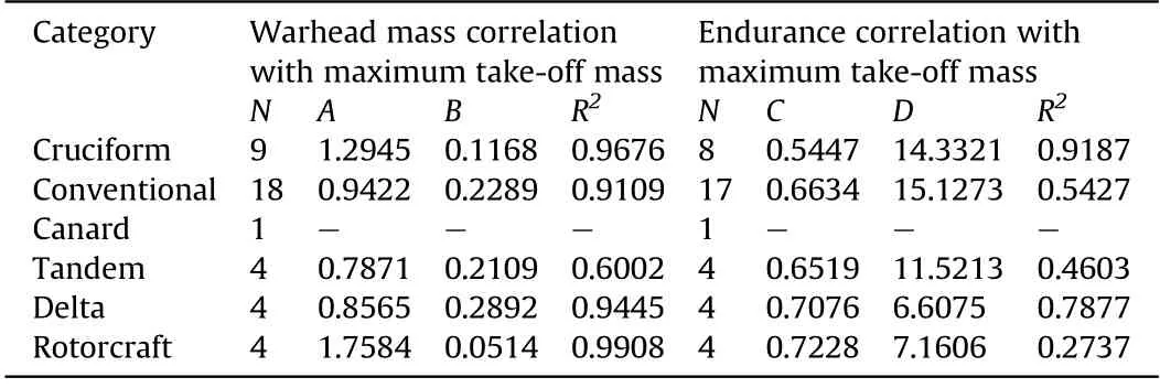
Table 2 Coef ficients for the power law correlations of warhead mass and endurance with maximum take-off mass.

Table 3 Correlation of the product of endurance and warhead mass(kg min)with maximum take-off mass.

In the above discussions,the wing aspect ratio was mentioned several times as an important design parameter to achieve high endurance.The aspect ratio is therefore presented as function of endurance in Fig.5.
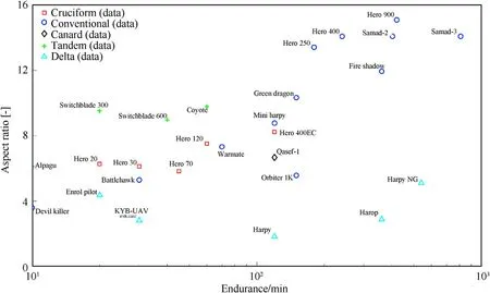
Fig.5.Wing aspect ratio and endurance for different categories of loitering munitions.
The wing aspect ratio is a key factor with respect to aerodynamic performance(lift over drag ratio)and thereby also with respect to endurance.Other factors such as the detailed aerodynamic shape(fuselage shape,aerofoils,excrescences,etc.)and advanced systems such as active flow control and morphing wings also signi ficantly affect the aerodynamic performance.This explains part of the variations in the data reported in Figs.1-4.The analysis of loitering munitions reported in this article is however largely based on data obtained in the public domain such as pictures.From these public domain sources it is usually not possible to determine details of the aerodynamic shape and information about the use of advanced systems.An impression of the possible variations in aerodynamic performance for a given wing planform is given by means of an example.It was demonstrated in Ref.[30]that the maximum lift over drag ratio of a tactical unmanned aerial vehicle with a total mass of 50 kg and a conventional wing design with an aspect ratio of 10 could be improved by approximately 16%through the use of aerodynamic shape optimization and active flow control.A second study of the same tactical unmanned aerial vehicle[31]demonstrated the bene fits of integrating the flight control system design and morphing wing systems on the flight performance.
Another interesting parameter from a flight performance perspective is the cruise speed.The cruise speed of loitering munitions is often not reported.However,the wing loading is representative for the speed at which the aircraft flies.This follows from the vertical equilibrium equation and the equation for the aerodynamic lift force(Eq.(8)).

The lift coef ficient(C)in cruise flight is typically in the range 0.3-0.6.For a given wing lift coef ficient and cruise altitude,the wing loading(W/S)determines the required airspeed.In case the dimensions of an aircraft are increased by a factor n,the wing area will increase with a factor nand the volume increases with a factor n.This is called the‘square cube law’and it explains directly why larger aircraft must fly faster than smaller aircraft with the same shape.
The square cube law can be observed in Fig.6.As maximum take-off mass increases,so does wing loading.In addition,differences between con figurations can be seen.The cruciform con figuration operates at signi ficantly higher wing loadings and therefore airspeeds than the conventional con figuration.Also the tandem con figuration typically has a higher wing loading.The wing loading of the conventional con figuration is lower because it tends to have a high aspect ratio and a relatively large wing surface area.No clear trend can be seen for the delta wing con figuration of which only a limited number of data points are available.Delta wings have a large internal volume for a given wing area.This allows for a large and heavy payload(warhead)which would result in a high wing loading.This seems to be the case for the two delta wing designs with a large maximum take-off mass.The dimensions of the loitering munitions are further analysed in Fig.7.
The dimensions are of primary importance for the launch method.The majority of loitering munitions is launched by one of the following two methods:
·Canister launch
·Rail launch
If a design can be folded into a canister,the length of the aircraft determines the minimum required length of the canister.The maximum wing span in turn is limited by the length of the canister and the con figuration type.Fig.7 shows that designs with a cruciform con figuration have a length more or less equal to the wing span.This means that the full length of the canister is used for the wing assuming that the wing is connected approximately to the middle of the fuselage.In other words,the wing span of cruciform con figurations is limited by the canister length.Quite a few designs with a conventional or canard con figuration have a wing span larger than the fuselage length.This makes it dif ficult to fold the design into a container.Such designs are typically launched from a rail.For designs with a tandem con figuration,the situation is different.These aircraft have a wing at the front of the fuselage and a wing at the rear.This makes it possible to have a wing span twice the length of the fuselage(b=2L)folded into a canister.Hence,the tandem con figuration allows for a relatively large aspect ratio whilst satisfying the requirement to be launched from a canister.Finally,delta wing designs cannot be folded easily into a canister.However,for a given wing area and internal volume,the delta wing has a low wing span compared to other con figurations.This can be bene ficial for the launcher design.The Israel Aerospace Industries(IAI)Harop loitering munition has a special delta wing design.It features wing tips which unfold directly after launch[32].By doing so,the aerodynamic performance is improved.This vehicle also has a canard con figuration which makes it inherently agile.
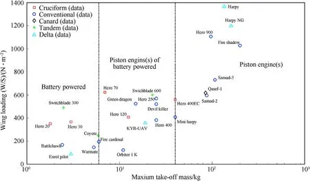
Fig.6.Wing loading and maximum take-off mass for different categories of loitering munitions.
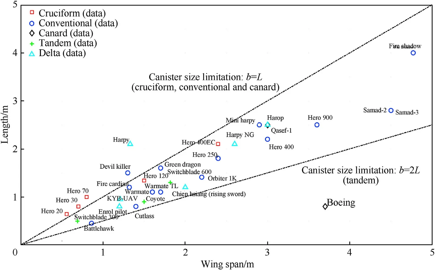
Fig.7.Wing span and aircraft length for different categories of loitering munitions.
4.Example case studies
Loitering munitions are frequently used in the con flict in Yemen.Three speci fic types of loitering munitions used in this con flict are presented as case study in the current section.The flight performance of the Samad 2 and Samad 3 is analysed first.These loitering munitions are designed for long range missions.Next,a loitering munition with a delta wing design is analysed with a focus on its susceptibility to wind gusts.
4.1.Long range conventional con figuration-samad 2/3
The Samad loitering munition is operated by Ansar Allah,the Houthi rebel movement.This loitering munition has been used in various long range attacks on targets in Saudi Arabia.Details of these attacks and the design of this loitering munition are well documented in the yearly reports of the United Nations Panel of Experts on Yemen[3,33].Based on information available in the public domain,flight performance simulation models of the Samad 2 and Samad 3 loitering munition were developed.These simulation models are largely based on empirical methods to predict the aerodynamic characteristics in terms of lift drag polars[34-40],the propulsion system characteristics in terms of thrust and fuel consumption as a function of airspeed and altitude[41-44]and the mass of the vehicle and the fuel[29].Mission analyses are performed by means of numerical simulation of the point mass equations of motion.These equations include effects of headwind and crosswind.Two lift drag polars were computed to represent the aerodynamics.The first lift drag polar was constructed based on the DATCOM method[35]in combination with an empirical method(ESDU)to estimate the drag of the antenna of the vehicle[34].The second lift drag polar was created by estimating the zero lift drag based on handbook methods[36-39]and by estimating the lift induced drag based on a vortex lattice method[40].The approach to estimate the drag of the antenna was the same as for the first lift drag polar.Results are presented in Fig.8.Higher fidelity methods to analyse the aerodynamics could not be employed due to a lack of detailed information on the geometry.The uncertainty in the aerodynamic data was accounted for by means of Monte Carlo simulations.
Details of the speci fic engines used on this aircraft are reported in the earlier mentioned United Nations report[3].The power speci fic fuel consumption of these engines are reported by the manufacturer.Less information is known about the propeller.The general dimensions of the propeller were obtained through analysis of a limited number of pictures.The thrust of the propeller was estimated using the parametric ESDU method which relies on a large amount of wind tunnel data of different propellers[41,42].Finally,estimations were made of the effect of the partial blockage of the propeller by the fuselage[43].The final static thrust calculated was within 5%of the value suggested by the engine manufacturer in case their recommended propeller was used[45].Results are presented in Fig.9.
If more details of the propeller are known,it is possible to determine the propeller thrust as a function of advance ratio by using computational fluid dynamics.Oktay and Eraslan demonstrated that accurate results can be obtained for propellers used on quad rotor unmanned aerial vehicles[46].All details on the methods used to develop the simulation models of the Samad-2 and Samad-3 are described by Voskuijl et al.[45].
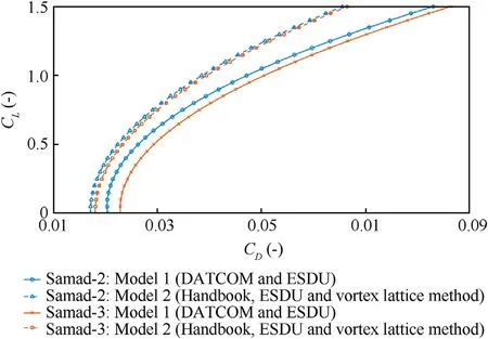
Fig.8.Lift drag polars of the Samad-2 and Samad-3 at Mach 0.15.
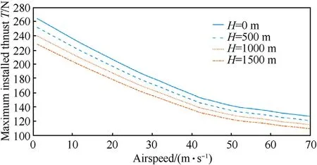
Fig.9.Maximum installed thrust as a function of airspeed and altitude(ISA condition).
On August 17,2019 an attack was made with 10 unmanned aerial vehicles on an oil re finery in Shaybah,Saudi Arabia,near the border of the United Arab Emirates.This attack was claimed by the Houthi rebel movement and the United Nations Panel of Experts on Yemen con firmed that the Samad-3 loitering munition was used[3].In order to give an impression of the flight performance capabilities of the Samad 3 in terms of range,endurance and speed,the simulation model is used to simulate this speci fic attack on Shaybah.The simulation includes realistic operating conditions including the actual weather conditions(wind,temperature and air density)of the day of the attack.It is assumed that the Samad-3 is launched from a location near Sa'dah in Yemen which is within Houthi controlled territory at a distance of 1234 km from Shaybah.Sa'dah is at a signi ficantly higher elevation than Shaybah.It is further assumed that the loitering munition follows a prede fined flight path at 500 m above the terrain and that the best airspeed for maximum range is selected throughout the flight(considering headwind and crosswind effects).The mission is divided into 6 waypoints.The weather conditions at each waypoint are provided in Table 4.These conditions were obtained from a web based application that stores worldwide meteorological data[47].Some key flight performance parameters throughout the mission are displayed in Fig.10(see Table 5).

Table 4 Atmospheric conditions during attack on Shaybah on August 17,2019 with a Samad-3.

Table 5 Comparison of sensitivity to wind gusts(flight path accuracy)between the Delta wing UAV and Samad 2/3 loitering munitions.
The baseline flight performance model indicates that the fuel tanks of the Samad-3 are approximately 20%full at the end of the flight.The total fuel volume of the Samad-3 is estimated to be 47.3 L[45].It should be noted that the simulation model has several uncertainties since it is based on a limited amount of information available in the public domain.A Monte Carlo simulation was therefore conducted to analyse the effect of these uncertainties on the outcome of the simulation.For all possible combinations of uncertainties,the Samad-3 is able to reach Shaybah from Yemen.This con firms that the Samad-3 has long rang capabilities.More details on its range and endurance can be found in Ref.[45].
Other flight performance parameters besides range and endurance are also analysed.The climbing and turning performance of the Samad-2 when operating at its maximum take-off weight and at sea level conditions(international standard atmosphere)is summarized in Fig.11.This figure is a so-called doghouse chart.The aircraft performance theory required to create this chart is presented in Appendix A.4.The figure displays for the range of achievable airspeeds in steady flight(constant airspeed)which turn rates can be achieved in combination with the achievable climb or descent rate.For example,when the Samad-2 descents with 5 m/s,the maximum airspeed(without turning)is approximately 78 m/s.At the same rate of descent,the aircraft can turn with about 46/s.In order to achieve that turn rate,the aircraft must fly at approximately 48 m/s.The corresponding turn radius and load factor at this condition are 60 m and 4 g respectively.It should be noted that the performance of this airplane improves signi ficantly when it is operating at a lower weight(for example at the final flight stage when most fuel is burnt).
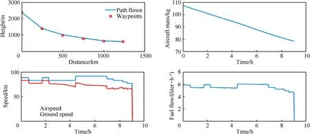
Fig.10.Simulation of the attack on Shaybah on August 17,2019 with a Samad-3 under realistic weather conditions.
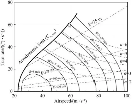
Fig.11.Doghouse chart of the Samad-2 at sea level conditions(international standard atmosphere)and maximum take-off weight.
4.2.Delta wing UAV
Since 2019,it is reported that Houthi rebels in Yemen have been using a new type of loitering munition with a delta wing con figuration for several attacks[3].Examples are the attacks on Saudi Arabian oil pumping stations in Dawadimi and A fif and the wellknown attack on the oil installations of Abqaiq on September 14,2019.This vehicle carries a warhead of 18 kg which is stored in the nose cone and appears to be designed to penetrate heavy armour[3,33].The dimensions of the Delta wing UAV are reconstructed based on the analysis of several pictures of debris available in the public domain(see Fig.12).The estimated dimensions are in close agreement with the wing span and vehicle length reported by the Panel of Experts on Yemen[3].It has a wing surface area(excluding the winglets)of 2.17 mand a high main wing leading edge sweep angle of 53.Altogether this results in a low aspect ratio(A≈1.95)con figuration.The vehicle is powered by a 28 kW Wankel engine with a single propeller.This engine has a very high power to weight ratio.
An analysis of the aerodynamic characteristics of the delta wing UAV was conducted.A vortex lattice method with a leading edge suction analogy was used to predict the lift and induced drag[49-52].This method is particularly suitable for the analysis of low aspect ratio designs.It is unfortunately not possible to use higher fidelity methods without more detailed knowledge of the aerofoils used in the design.The aerodynamic analysis is extended with a flat plate theory[36]to estimate the zero lift drag coef ficient.Results of the analysis indicate that the value of the lift curve slope d C/dα equals 2.60[rad].The lift curve slopes of the Samad 2 and 3 are predicted within the range of 5.92-5.99 by different aerodynamic analysis method.The estimated lift curves of both the Samad and Delta wing UAVs are presented in Fig.13 for angles of attack up to 10(within the linear regime).
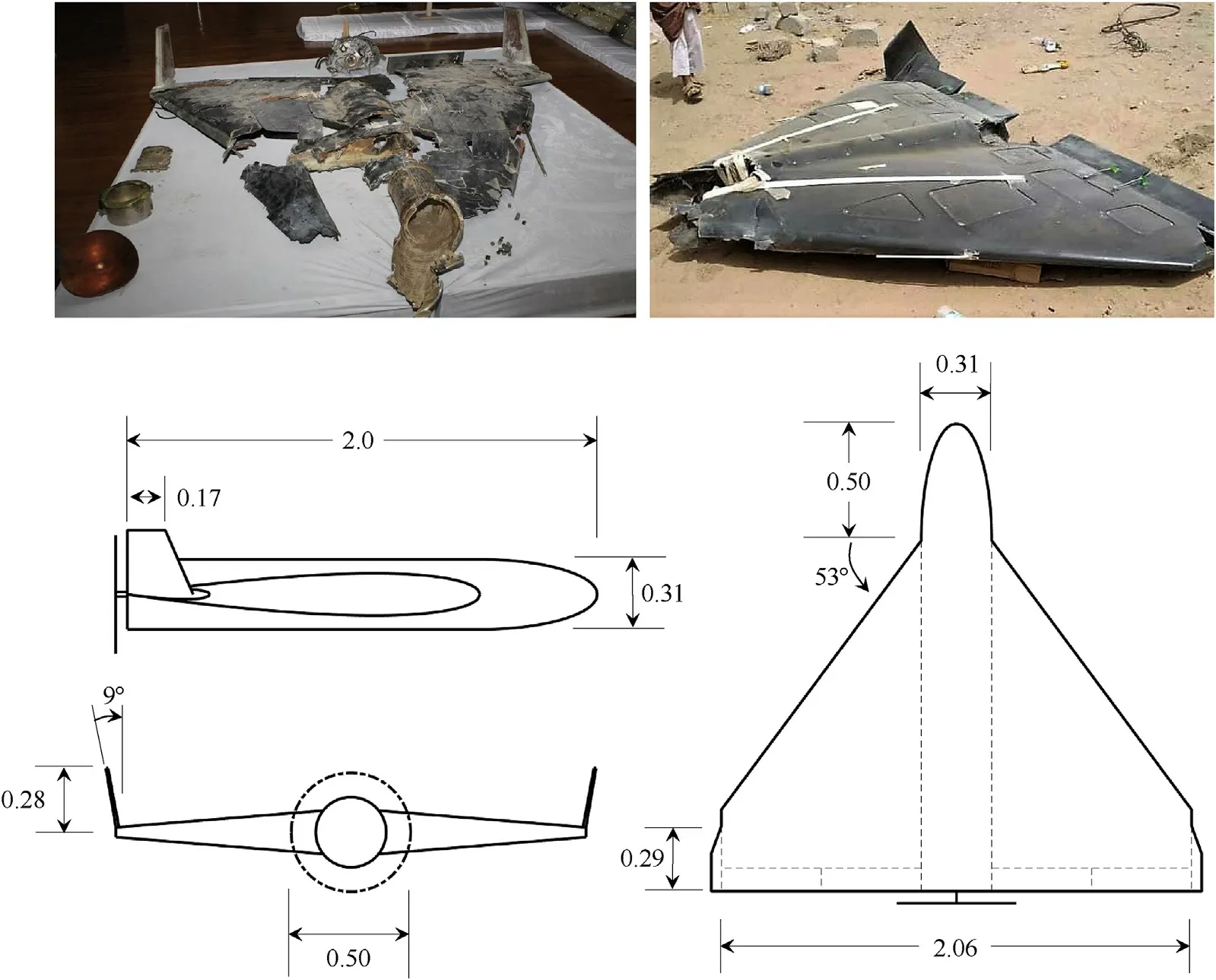
Fig.12.Debris of delta wing UAV(sources[3,48])and three view drawing(dimensions in meters)based on analysis of various pictures available in the public domain.
The maximum take-off mass of the delta wing UAV can be estimated based on aircraft design sizing correlations.Verstraete[29]has reported sizing correlations for unmanned aircraft.These relations predict a maximum take-off mass of 82 kg.However,these correlations are largely based on designs with a higher aspect ratio and are possibly on the low end.Based on the correlations presented in Fig.2 and Table 2,one would rather expect a maximum take-off mass of 124 kg.Based on the range of mass estimates,the wing surface area and the lift curve slope,a comparison between the sensitivity to wind gusts can be made(Eq.(4)).
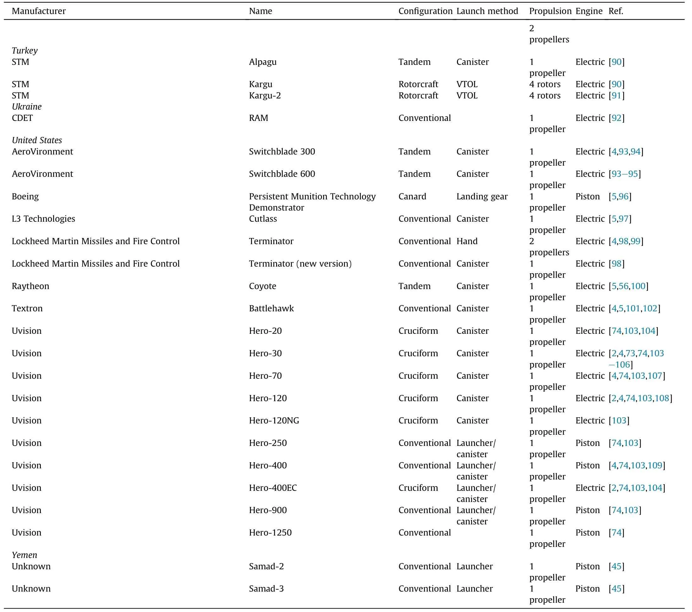
Table B1(continued)
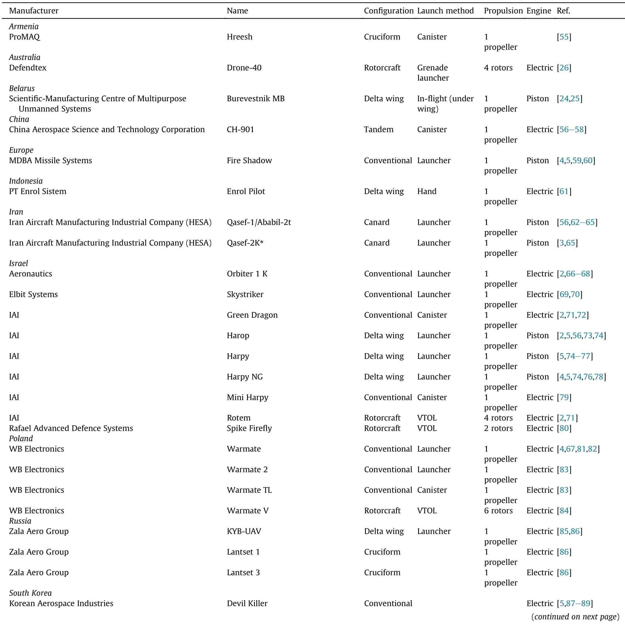
Table B1 Loitering weapon systems general characteristics

Table B2(continued)
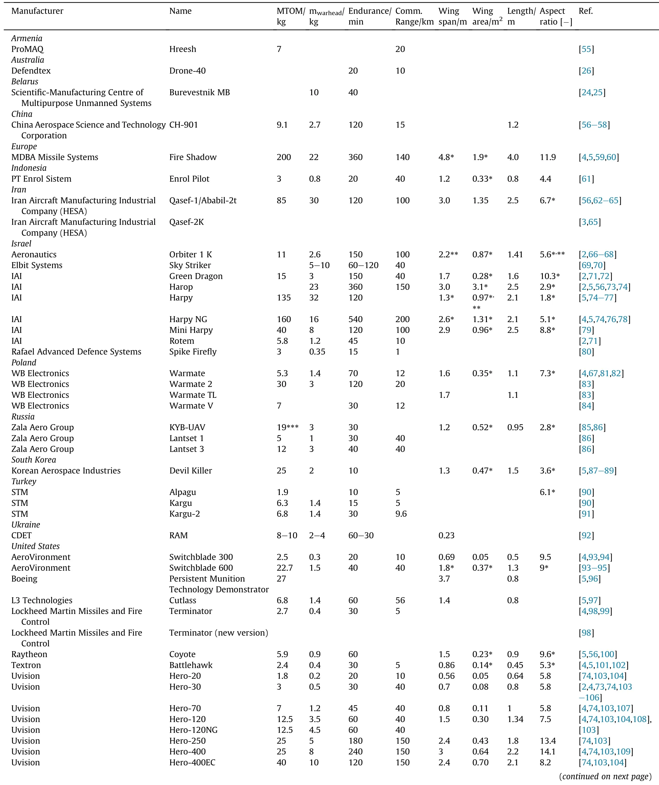
Table B2 Loitering weapon systems performance,weights and dimensions.
The comparison indicates that the conventional design of the Samad 2 and 3 which have the same payload weight as the delta wing UAV(warhead of 18 kg)is signi ficantly more susceptible to wind gusts than the delta wing UAV.Hence,precision flight path control in realistic operating conditions is easier with the delta wing UAV when symmetric flight is considered.The directional stability and control of a delta wing con figuration is a signi ficant challenge[22].In addition,the delta wing UAV has a much smaller wing span compared to the Samad 2 and 3(2.06 m versus 4.5 m)which is bene ficial for the launcher design.Finally,the delta wing UAV has an engine which delivers about twice as much shaft power than the engine installed on the Samad 2 and 3.Considering the fact that the wetted surface area of the delta wing UAV is less than the Samad 2 and 3,it will have a signi ficantly higher maximum airspeed.Altogether,the analysis described highlights the advantages and disadvantages of a loitering munition with a delta wing design compared to a loitering munition with a conventional design from an aircraft performance perspective.
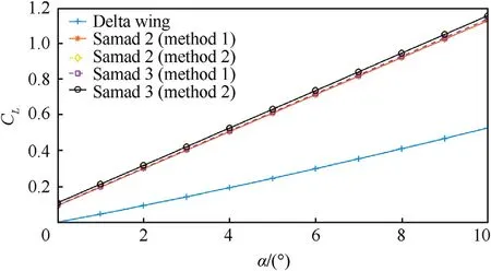
Fig.13.Estimates of the lift curves of the Samad-2,Samad-3 and Delta wing UAV.
5.Conclusions and recommendations
A comprehensive database of 52 loitering munitions developed in 16 countries was developed based on data available in the public domain.The database includes information on the maximum takeoff mass,warhead mass,dimensions,and flight endurance and communication range.In addition,the launch methods and vehicle con figurations are reported.Based on a statistical analysis of the database in combination with aircraft performance theory tailored to loitering munitions several conclusions can be drawn.Six main con figurations can be identi fied;(1)conventional,(2)delta wing,(3)tandem wing,(4)canard,(5)cruciform,and(6)rotorcraft.Loitering munitions can also be categorized based on their propulsion system(battery electric or gasoline powered)or launch method(hand launched,rail launched and canister).For long range applications,the preferred design solution is the conventional con figuration.The maximum vehicle mass and warhead mass are 200 kg and 32 kg respectively.The maximum reported endurance is 9 h and flight ranges in excess of 1500 km are estimated for some vehicles.For urban combat,rotary wing vehicles are used because of their vertical flight capability.These vehicles can typically carry grenade size warheads.The cruciform con figuration is bene ficial in case precision flight path control is of prime importance.The tandem wing con figuration combines the bene fits of a canister launch and relatively high aspect ratio wings suitable for long range flight.The delta wing design provides a large internal volume and a high terminal attack airspeed.
The statistical trends are presented in various graphs and regression analyses are performed to obtain the relations between warhead mass,endurance and maximum take-off mass for each loitering munition con figuration.Based on these trends,performance estimations can be made of vehicles of which only general dimensions are known.For example dimensions based on pictures in the public domain.
Two case studies of vehicles used currently in the con flict in Yemen are reported.A simulation of the Samad 3 loitering munition demonstrates that the attacks on an oil re finery in Shaybah,Saudi Arabia(August 17,2019)could have been launched from Houthi territory in Yemen(>1200 km range).This illustrates the long range capabilities of loitering munitions with a conventional con figuration.The second case study investigates a new delta wing design used by Ansar Allah,the Houthi rebel movement in Yemen.Compared to the Samad 2 and 3,this delta wing loitering munition is much less susceptible to atmospheric disturbances(bene ficial for precision flight path control),it has a large internal volume to store a warhead and other systems and it has a much smaller wing span(bene ficial for launcher size).
It is recommended to continuously update the loitering munitions database once new developments and designs are reported.Second,it is recommended for future research to perform high fidelity simulations of selected designs once more detail becomes available about their respective geometries(for example air foils used)and structural designs.Such high fidelity simulations can be used for veri fication and validation purposes.A third recommendation is to perform a quantitative analysis of the flight path precision capability of an attack expressed in a parameter such as the circular error probable for different con figurations such as the cruciform design.
The authors declare that they have no known competing financial interests or personal relationships that could have appeared to in fluence the work reported in this paper.
This research did not receive any speci fic grant from funding agencies in the public,commercial,or not-for-pro fit sectors.
A.1 Loitering endurance
The loitering endurance(E)is de fined as the total flight time in cruise flight.In this appendix,Eqs.(1)and(2)for loitering endurance of both gasoline and battery-electric unmanned aircraft are derived.Fuel or electric energy is also required for other mission phases such as take-off,climb and descent.These mission phases are not included in the analysis since the main purpose is to determine which design parameters have the largest in fluence on the loitering endurance.Endurance is the integral of the total time(t)from the start of the cruise phase until the end of the cruise phase(Eq.(A.1)).

In order to calculate this integral it is necessary to determine the required power for cruise flight and the associated fuel flow in case of an internal combustion engine or the consumption of the energy stored in the batteries in case of an electrically powered aircraft.The cruise flight of the aircraft can be assumed quasi-steady since altitude and flight speed(V)will only change gradually.Hence,the following equilibrium equations(Eq.(A.2)and Eq.(A.3))apply.

where Cand Care the dimensionless lift and drag coef ficients.These coef ficients depend on the shape of the aircraft,the angle of the vehicle with respect to the air flow and the Mach and Reynolds numbers.L and D are the aerodynamic lift and drag force respectively.T represents the thrust provided by the propulsion system.The power required(P)for cruise flight is the drag force multiplied with the airspeed(Eq.(A.4)).

In case of aircraft with an internal combustion engine,the time can be related to the fuel flow(F)as de fined in Eq.(A.5)and the fuel flow is related to the shaft power(Eq.(A.6)).

The shaft power(P)is converted into power available(P)for flight by means of the propeller(Eq.(A.7)).

In this equation,ηrepresents the propeller ef ficiency.For electrically powered aircraft,the shaft power depends on the time rate of change of the energy stored in the batteries and the ef ficiency of the conversion into mechanical power(η)(see Eq.(A.8)).

Combining equations A.1 and A.4-A.8 yields an equation for the endurance of aircraft powered by a piston engine(Eq.(A.9))and an equation for the endurance of an electric aircraft powered by batteries(Eq.(A.10)).
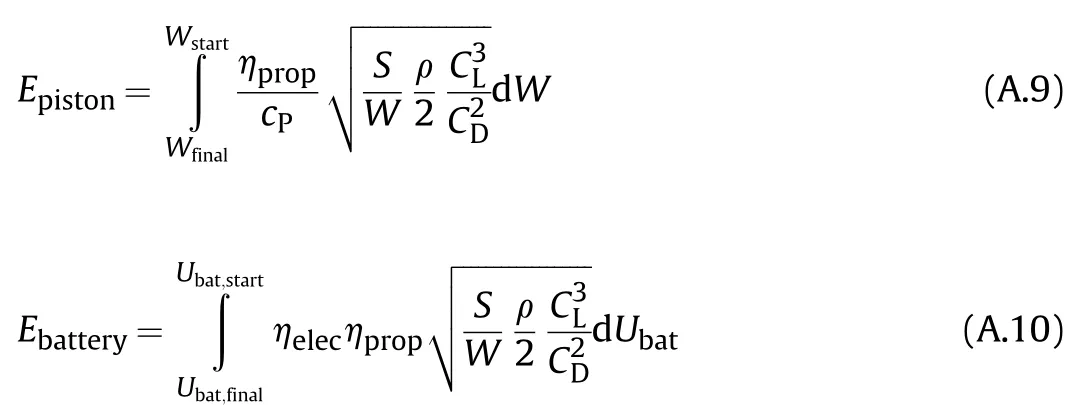
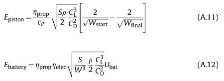
It is assumed that the ef ficiencies and the power speci fic fuel consumption are constant for the range of flight speeds and flight altitudes of interest.In case a cruise flight is conducted at constant altitude and constant angle of attack,then the air density,the lift coef ficient and the drag coef ficient are all constant.For this speci fic flying strategy,the endurance integrals can be solved(see Eq.(A.11)and Eq.(A.12)).
The lift drag polar describes the relation between the lift coefficient and the drag coef ficient.A two term lift drag polar is used in this derivation(Eq.(A.13)).

In real life applications it is more accurate to use a three term lift drag polar[53].However,this derivation is primarily intended to obtain more insight in the physics of the problem and the in fluence of aircraft design parameters on endurance.In case a two term lift drag polar is used,the optimal ratio of lift coef ficient and drag coef ficient for maximum endurance can be determined as presented in Eq.(A.14),Eq.(A.15)and Eq.(A.16).
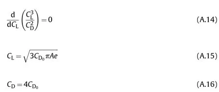
Based on this result the final loitering endurance equations(Eq.(A.17)and Eq.(A.18))can be determined.
A.2 Terminal attack dive airspeed
A schematic representation of the forces acting on a loitering munition in a powered descending flight at constant airspeed(V)
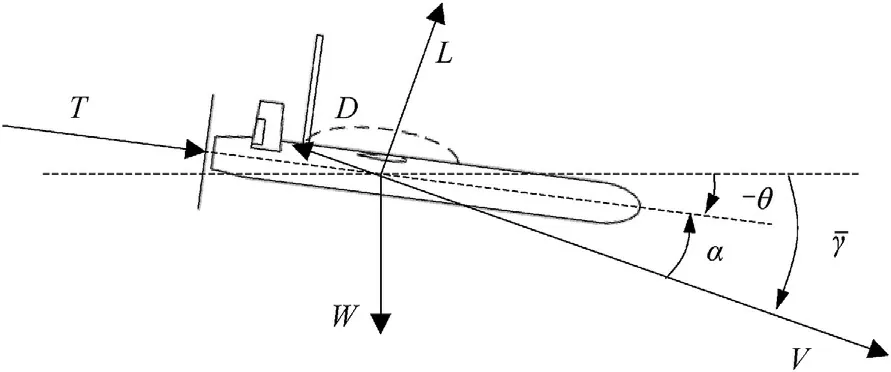
Fig.A1.Descending flight at constant airspeed and descent angle.

The angleθis the attitude of the aircraft relative to the horizon.The angle of attack(α)is the angle between the air flow and the aircraft.Based on this schematic,the point mass equations of motion can be derived for a powered steady rectilinear descending flight(Eq.(A.19)and Eq.(A.20)).

Eq.(A.2)shows that at the maximum airspeed,the lift coef ficient(C)will be small and therefore the angle of attack as well.Assuming that the thrust force is in line with the nose of the aircraft,the thrust angle of attackαwill be close to zero.The effect of the thrust angle of attack on the maximum airspeed can therefore be neglected.Equations A.3 and A.4 representing the lift and drag force can be inserted in these equations of motion.By doing so,the airspeed appears as a variable.Furthermore,when Eq.(A.19)is multiplied with the airspeed,the so-called power equation is obtained(Eq.(A.21)).

To maintain equilibrium perpendicular to the flight path,Eq.(A.22)must be satis fied.

By combining equations A.21,A.22 and the equation representing the lift drag polar(Eq.(A.13))the following relation(Eq.(A.23))is found:

In order to achieve the maximum airspeed,maximum shaft power should be provided by the propulsion system(Eq.(A.7)).

When the characteristics of the aircraft are known and the descent angle is de fined,Eq.(A.24)can be solved for the airspeed.
A.3 Sensitivity to gusts
If an aircraft encounters a vertical gust in horizontal flight,the angle of attack will change.As a consequence the lift will change and the aircraft will acquire an acceleration perpendicular to its flight path.The load factor(n),de fined as the lift divided by the aircraft weight is directly related to this acceleration.The encounter of a gust is presented in Fig.A2.

Fig.A2.Vertical gust encounter.
Assuming the aircraft encounters a sharp edged gust,the instantaneous change in the lift coef ficient can be written as follows(Eq.(A.25)):

It is further assumed that the slope of the lift curve is linear.The change in angle of attack(Δα)is related to the gust velocity(U)and the airspeed(V)of the aircraft(Eq.(A.26)).
An approximation of the instantaneous change in load factor follows(Eq.(A.27))by combining Eq.(A.24)and Eq.(A.25)and by assuming that the airspeed is signi ficantly larger than the gust velocity.


In reality,the gust will not be sharp edged.Furthermore,depending on the size of the aircraft in relation to the gust length,the wing may experience the gust at a different time than the horizontal tail plane or canard.To account for these factors,Eq.(A.26)may be multiplied with a parameter K.More details on this factor are provided by Hoblit[54].
A.4 Doghouse charts
A doghouse chart summarizes the turning and climbing/descending performance of an aircraft for a given flight altitude and thrust setting.This chart is based on the point mass equations of motion for a steady non-sideslipping banked turn[44](see Eq.(A.28),Eq.(A.29)and Eq.(A.30)):
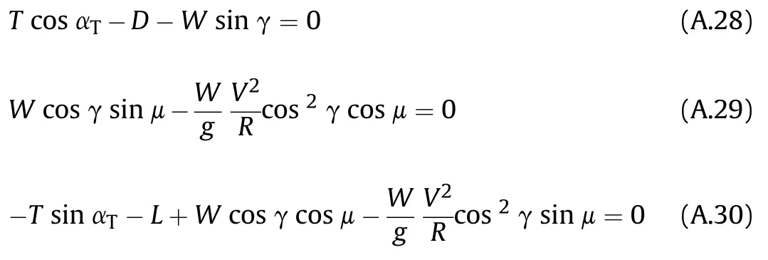
whereμrepresents the aerodynamic angle of roll.The turn radius(R)and turn rate(˙χ)are related through the airspeed(Eq.(A.31)).

To achieve the best turning performance,maximum thrust should be applied.Lift,drag in the equations above are a function of the airspeed,the air density and the lift coef ficient and drag coef ficients.The relation between the lift coef ficient and drag coefficient is determined by the lift-drag polar.The angle of attack follows from the lift curve slope if the lift coef ficient is known.Based on the inclination of the thrust vector with respect to the aircraft body axis,the thrust angle of attack can be computed.
If the thrust(T)is set at its maximumvalue and the aerodynamic characteristics of an aircraft are known,then for a given airspeed(V),air density(ρ)and turn rate(˙χ),the point mass equations of motion can be solved iteratively in order to find the required lift coef ficient(C),flight path angle(γ)and aerodynamic angle of roll(μ).The rate of climb or descent associated to a speci fic turn rate and air speed follows from Eq.(A.32).

杂志排行
Defence Technology的其它文章
- High explosive unexploded ordnance neutralization-Tallboy air bomb case study
- Dynamics and rebound behavior analysis of flexible tethered satellite system in deployment and station-keeping phases
- Finite element analysis of functionally graded sandwich plates with porosity via a new hyperbolic shear deformation theory
- Investigation on the penetration of jacketed rods with striking velocities of 0.9-3.3 km/s into semi-in finite targets
- The effect of strain rate on compressive behavior and failure mechanism of CMDB propellant
- Adaptive target and jamming recognition for the pulse doppler radar fuze based on a time-frequency joint feature and an online-updated naive bayesian classi fier with minimal risk
