Dynamics and rebound behavior analysis of flexible tethered satellite system in deployment and station-keeping phases
2022-03-29YueZhangXinJiangZhengfengBaiJiawenGuoChengWei
Yue Zhang ,Xin Jiang ,Zheng-feng Bai ,Jia-wen Guo ,Cheng Wei
a School of Space Science and Technology,Xidian University,Xi'an,710126,China
b School of Astronautics,Harbin Institute of Technology,Harbin,150001,China
c Department of Mechanical Engineering,Harbin Institute of Technology,Weihai,264209,China
Keywords:Tethered satellite system Dynamic model Rebound Deployment ANCF-ALE
ABSTRACT The tether deployment of a tethered satellite system involves the consideration of complex dynamic properties of the tether,such as large deformation,slack,and even rebound,and therefore,the dynamic modelling of the tether is necessary for performing a dynamic analysis of the system.For a variablelength tether element,the absolute nodal coordinate formulation(ANCF)in the framework of the arbitrary Lagrange-Euler(ALE)description was used to develop a precise dynamic model of a tethered satellite.The model considered the gravitational gradient force and Coriolis force in the orbital coordinate frame,and it was validated through numerical simulation.In the presence of dynamic constraints,a deployment velocity of the tether was obtained by an optimal procedure.In the simulation,rebound behavior of the tethered satellite system was observed when the ANCF-ALE model was employed.Notably,the rebound behavior cannot be predicted by the traditional dumbbell model.Furthermore,an improved optimal deployment velocity was developed.Simulation results indicated that the rebound phenomenon was eliminated,and smooth deployment as well as a stable state of the station-keeping process were achieved.Additionally,the swing amplitude in the station-keeping phase decreased when a deployment strategy based on the improved optimal deployment velocity was used.
1.Introduction
Recently,increasing attention has been paid to tethered satellite systems comprising a satellite and a tethered subsatellite for practical space missions intended for atmospheric exploration,orbital transfer[1,2],target capture[3],spacecraft reentry[4],and so on.Orbital experiments[5]and scienti fic research have shown that uncontrolled tether deployment inevitably causes intense oscillations because of the Coriolis force and external perturbation[6],resulting in the complex dynamic behavior of the tethered satellite system[7].Furthermore,the attitude of the satellite can be in fluenced by its interaction with the tether[8].Therefore,precise prediction of the tether deployment dynamics is fundamental to the smooth deployment of a satellite and the subsequent attitude stabilization,which is crucial to the success of the space mission.
In view of the signi ficance of the tether model in dynamic equations of the tethered satellite system(TSS),several dynamic tether models have been proposed,such as the rod,discrete,and continuous models.The tether is usually simpli fied as a rod without consideration of its flexibility in the rod model[9],and this model has been commonly used in control theory research owing to its simplicity[10].The incapability of the rod model to describe the bending deformation of a tether was addressed by developing the discrete model in which lumped masses and massless springs were introduced[11]to predict the deformation of a tether.The continuous model is governed by partial differential equations(PDEs)whose analytical solutions are dif ficult to obtain,and numerical methods such as the Ritz and Galerkin methods used to transform the PDEs to ordinary differential equations are characterized by poor ef ficiency[12].
Numerous studies on TSS dynamics have been performed using the aforementioned tether models.Gou et al.investigated attitude control using a fractional-order controller based on the rod model without considering the out-of-plane perturbation[13],Yu et al.[14]investigated the stability of a TSS by using a flexible rod model and considering environmental perturbations,Zhong et al.investigated the dynamics of deployment and retrieval by using a hinged-rod tether model[15],Yu[16]studied the deployment strategy of a TSS by using a mass distributed model,and Luo et al.used a discrete spring-mass model to study the attitude stabilization of a satellite with closed-loop feedback control under Jperturbation[17].
Because of the large slenderness ratio of the tether,it shows weak resistance to bending deformation.This renders it susceptible to large deformations when external forces are applied to it,which in turn result in the tether undergoing large-amplitude oscillations and even tumbling motion[18].Since the rod and discrete models adopted in the above studies have been simpli fied in the modeling of flexible tether dynamics,the complex con figuration of a tether during deployment is dif ficult to captured with these models.Motivated by the application of the Eulerian method in computational fluid mechanics,the conventional finite element was extended in an arbitrary Lagrangian-Eulerian(ALE)framework to capture the large deformation of solid mechanic problems[19,20].In this context,Nazem et al.investigated optimal dynamics of the partial space elevator with a moving climber[21].Li et al.proposed a novel concept of looped tether transportation and researched the high order dynamic characteristics of a tether transportation system[2,22].These works are implemented based on the nodal position finite element method in the framework of ALE description.In addition,Peng et al.investigated the friction effect between a sliding joint and the cable based on the ALE approach[23].Recently,absolute nodal coordinate formulation(ANCF)[24]based flexible elements have been found to be capable of accurately describing large deformations,and they have been widely adopted for the dynamic analysis of flexible systems undergoing large-scale motion[25],such as a space manipulator and satellite mesh re flector.Using a variable-length element associated with the ANCF,Kawguti et al.investigated the time-varying length of a planar cable element[26].Tang et al.[27]proposed the ANCFarbitrary Lagrange-Euler(ANCF-ALE)model and studied its application to a tethered satellite formation;they found that the model could accurately predict the dynamic characteristics of the tether during tether deployment.Since the gravitational gradient force and Coriolis force in the space orbit environment were not considered in the ANCF-ALE model,the actual dynamic characteristics of the tethered satellite in space,such as the repeated occurrence of the rebound phenomenon,cannot be obtained.Luo et al.investigated the dynamics of a spinning three-body tethered satellite formation with piecewise deployment velocity[28].In terms of the control of TSS,many meaningful works have been done by researchers[29-32].Steindl A et al.combined the optimal control theory with the finite element method to achieve a smooth deployment in the application of tethered satellites[29].Li et al.investigated the suppression of the libration motion of partial space elevator[30].The author and coworkers also proposed a new multiphysics finite element method to analyze the deorbit dynamics of space debris using a two-stage energy control strategy[31].Furthermore,in combination with a lumped mass model,a time-optimal deployment from a trivial down hanging con figuration close to the space ship to another one was derived by Pontryagin's Maximum Principle[32].
The repeated occurrence of the rebound phenomenon,which is characterized by the tether's state alternating between the stretched and slack states in the deployment or station-keeping phase,poses a major challenge to the successful deployment and subsequent attitude stabilization of satellites.This phenomenon is caused by the tether flexibility and the effect of the orbital environment.However,limited by the accuracy of the dynamic model of TSS,few studies have investigated the rebound behavior of the TSS in the deployment and station-keeping phases.Accordingly,the repeated occurrence of the rebound phenomenon was investigated in this study using an ANCF-ALE-based dynamic model that considered the flexibility and length variation of the tether as well as the orbital environment's effect on the TSS.
This paper is organized as follows:An ANCF-ALE tether element model is derived in Section 2 and a dynamic model of a TSS in the orbital coordinate frame is presented in Section 3.Section 4 outlines the optimal procedure for transforming the optimal problem into a nonlinear programming(NLP)problem on the basis of previous work[33].Section 5 discusses the veri fication of the established dynamic model through numerical simulation.Furthermore,the rebound phenomenon caused by an improper optimal deployment strategy in the deployment and station-keeping phases is discussed.Then,an improved deployment strategy for the TSS is developed to eliminate rebound behavior.Finally,Section 6 concludes the paper.
2.ANCF-ALE tether element model
In this section,dynamic equations for the ANCF-ALE tether element[27]are derived to accurately predict the dynamic characteristics of the tether in the deployment and station-keeping phases.The following assumptions were made to develop a variable-length ANCF-ALE tether element:
(a)The cross section of the tether is approximately circular,and it is perpendicular to the axis of the tether.
(b)The torsional effect of the tether during its motion is neglected.
As shown in Fig.1,two nodes and an unstretched arc-length coordinate x were used to construct the variable-length element of the tether.From a perspective in practical application,the release and retrieval of a tether are controlled by the deployment mechanism mounted on the master satellite.In general,the tether cannot be released or retrieved by the subsatellite.Considering this fact,one moving material node is introduced in the ANCF-ALE element.Thus,the arc-length coordinate of the left node of the tether element is considered to be time-varying in order to consider the variation of the tether length,and it is expressed as

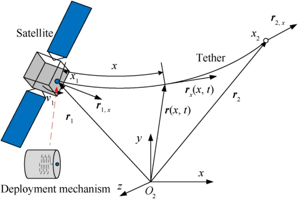
Fig.1.Variable-length ANCF-ALE tether element.
In particular,if the tether elongation velocity v(t)is not equal to zero,there exists mass flow entering/exiting the node,while v(t)=0 implies that there is no mass flow through the node,in which case the variable-length element degenerates to a constant-length ANCF element.The tether can be extended or retracted by setting the value of v(t).If v(t)>0(v(t)<0),the length of the element will increase(decrease).
It should be mentioned that the left node,with mass flowing through,is located at the boundary of the element instead of being fixed to the flowing particle.Hence,the left node is described by using the Eulerian approach while the right node.representing a material particle.is described using the Lagrangian approach.In generalized coordinates,a vector comprising positions and slopes can be expressed as

where r(i=1,2) denotes the global position vector of the nodes,r=∂r/∂x is the position gradient vector obtained by differentiation of rwith respect to the unstretched arc-length coordinate x.
Herein,Hermite interpolation functions are employed to de fine the element shape function matrix.The absolute position vector and gradient vector of an arbitrary material point on the element can be written as

where S is a time-varying shape function matrix.This matrix can be expressed as
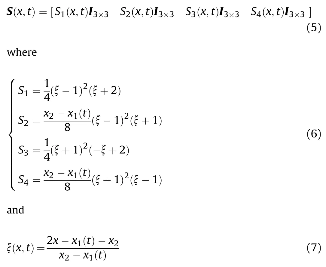
Note that the arc-length coordinate of the left node xis timevarying.The velocity and acceleration vectors of an arbitrary material point on the element can be derived by differentiating Eq.(3)with respect to time:


Notably,when˙x=0,the derived formulation in Eqs.(8)and(9)degenerates into the formulation for the case of a constantlength element.
Since the standard Lagrange equations are not valid for a system with variable mass,the more general D'Alembert's principle is used to derive the dynamic equations for the tether element.Substituting the virtual work of external forces applied on the tether element into the D'Alembert's equation yields


The virtual work of the external force and viscoelastic force can be speci fically formulated as
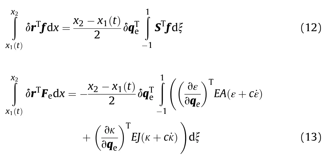
where E and J are the elastic modulus and cross-sectional moment of inertia of the tether,and c is the damping coef ficient.The variablesεandκrepresent the axial strain and curvature of the tether,and they are given by

According to Eq.(9),the virtual work of the inertial force can be expressed as

The dynamic equations of the tether element can be obtained by substituting Eqs.(12),(13)and(16)into Eq.(11)and considering that the coef ficient of virtual changeδqis zero:
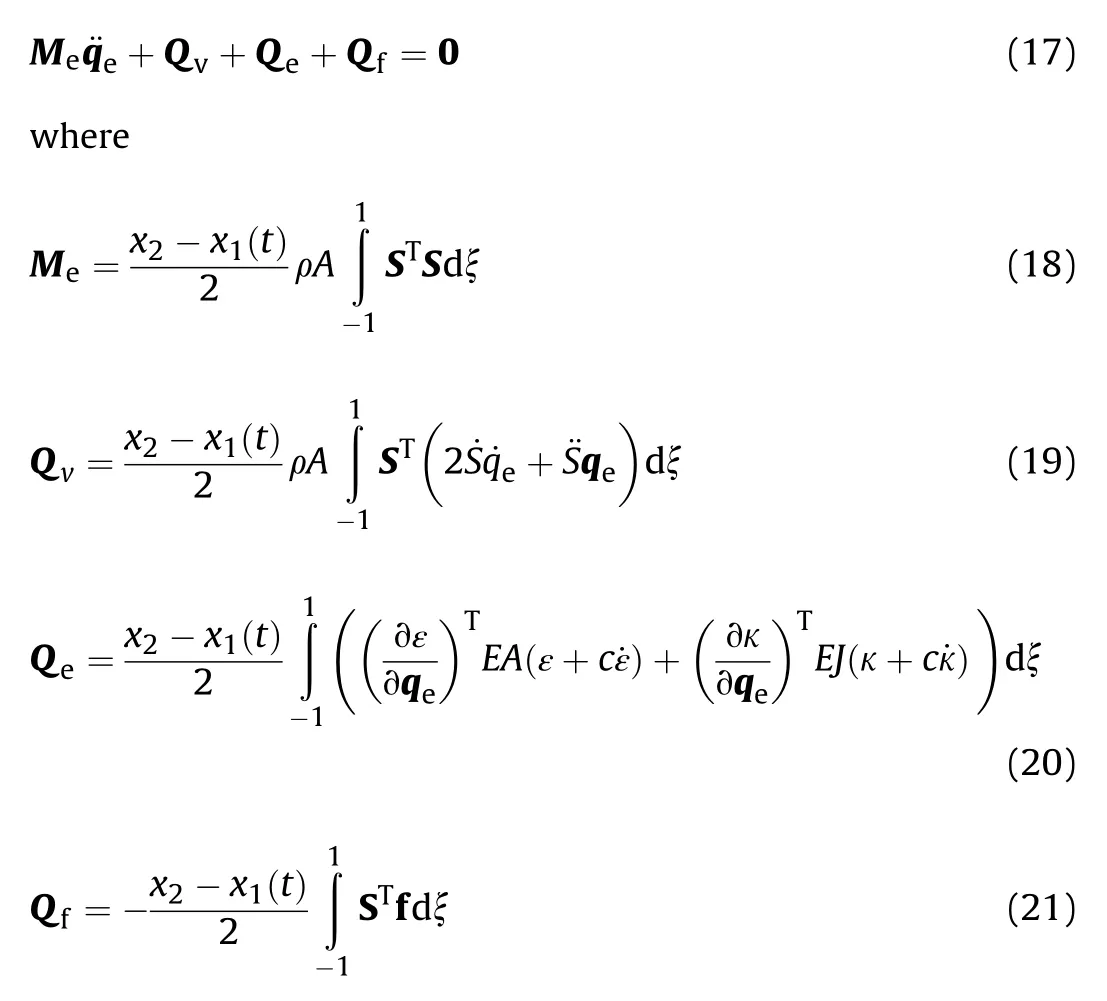
Here,Mis the mass matrix of the tether element,Qis the generalized force associated with the mass flow,and Qand Qdenote the generalized viscoelastic force and generalized external force,respectively.
3.Dynamic model of the TSS
Fig.2 shows a schematic of a TSS comprising a master satellite S1 and a subsatellite S2 in a circular Kepler orbit.The tether can be extended or retracted by using a deployment mechanism.The geocentric inertial coordinate frame(global coordinate frame)OXYZ and the orbital coordinate frame Oxyz are de fined to describe the motion of the TSS.The axis Ox of Oxyz points in the flight direction and the axis Oz is directed toward the earth's core.The direction of the axis Oy of Oxyz can be determined by the right-hand rule.As evident in Fig.2,the position of the TSS in the orbital coordinate frame can be de fined in terms of the in-plane angleθand the out-of-plane angleφ.
This paper mainly analyzes the relative motion between the satellites as well as the local motion of the tether,and focuses on the in fluence of tether characteristics on the dynamic behavior of tethered satellites during deployment and station-keeping phases.Therefore,a dynamic model of the TSS is developed in the orbital coordinate frame in this section.The generalized coordinate vector of the i th satellite can be de fined as
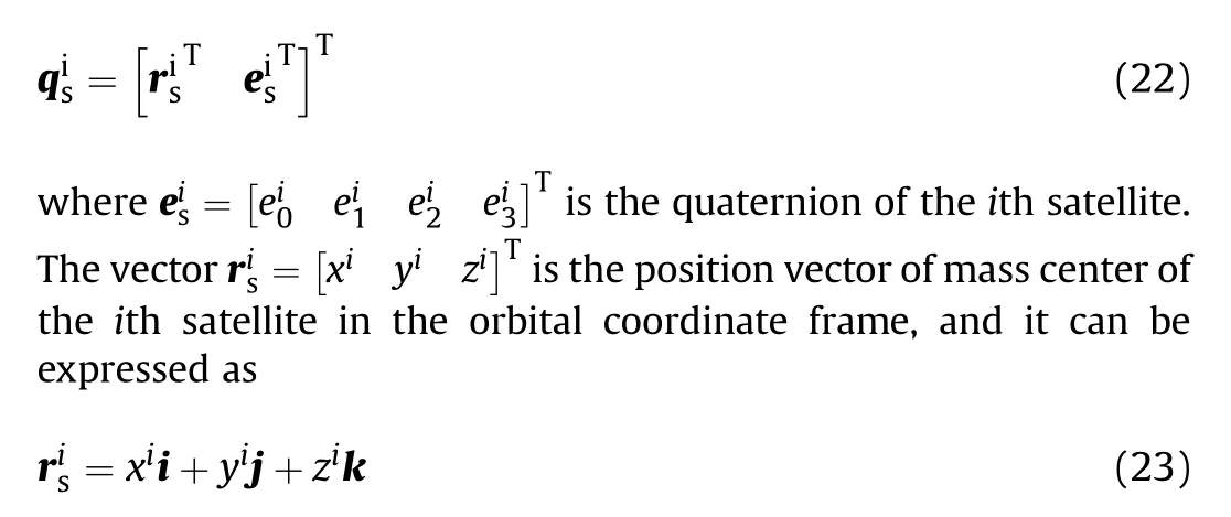
where i,j,and k are the unit vectors along the axes of the orbital coordinate frame.

If it is assumed that Ris the orbital radius and R=-Rk is the vector from point Oto point O,as shown in Fig.2,then the position vector of the i th satellite with respect to the center of the earth is The orbital coordinate frame is a moving reference system relative to the geocentric inertial coordinate frame.According to the acceleration composition theorem,in the presence of the earth's gravity,the absolute acceleration a(relative to geocentric inertial coordinate frame)and the relative acceleration a(relative to orbital coordinate frame)of the i th satellite have the following relation:
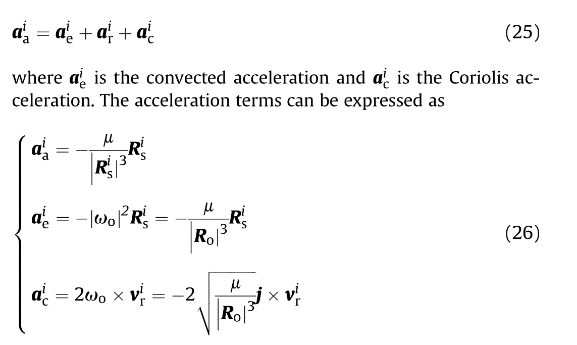
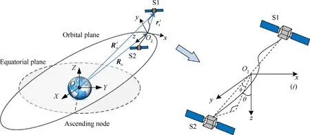
Fig.2.Schematic of a TSS.

Then,the force acting on the satellites in the orbital coordinate frame can be expressed as

In the above equation,the first term at the right end of the equation is the gravitational gradient force and the second term is the Coriolis force.
As with the satellites,the tether is also established in the orbital coordinate frame Oxyz(as can be seen in Figs.1 and 2).Similarly,the distributed external force acting on the tether element in Eq.(21)in the orbital environment can be obtained as

where r and˙r are the position and velocity vectors of an arbitrary point on the tether element(see Eqs.(3)and(8)).
The dynamic equations for the two rigid satellites with constraints can be expressed by using the Lagrange equations:
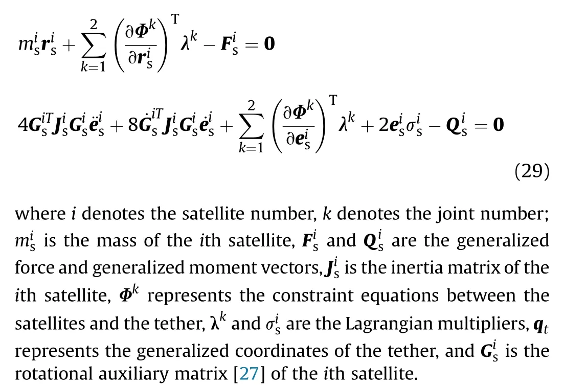
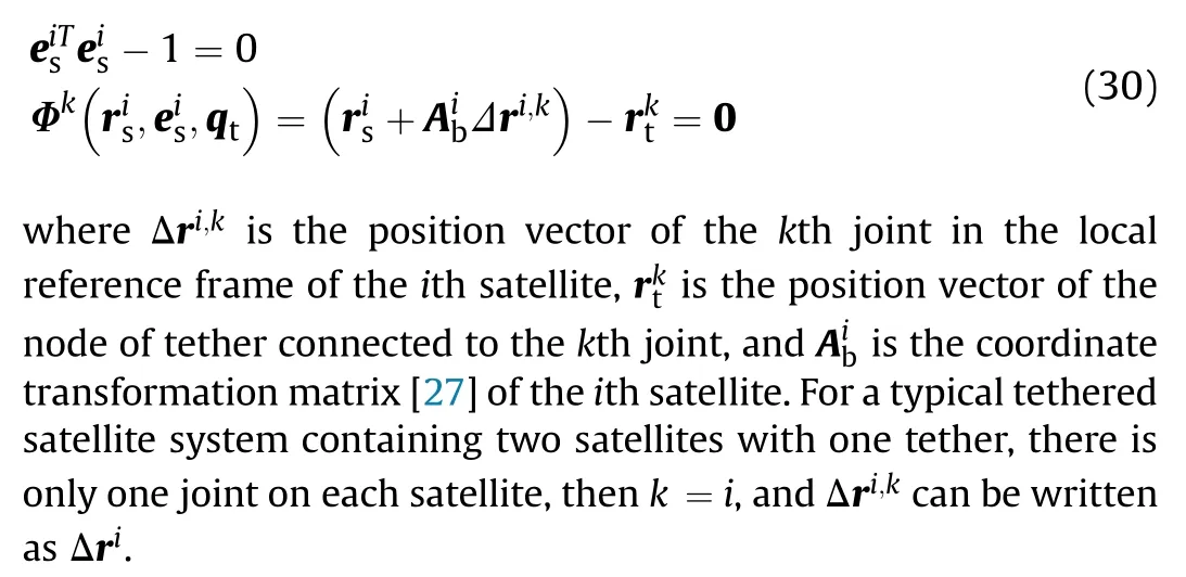
The constraint equations,including the quaternion constraint and constraints between the satellites and the tether can be expressed as
The simulation model of a tether usually consists of multiple tether elements,for a variable-length tether consisting of n-1 elements,the generalized coordinates of the tether can be expressed as follows:
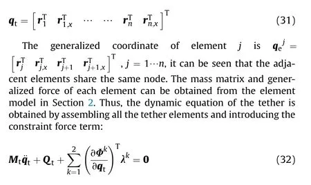
where Mis the mass matrix of the tether,and Qrepresents the generalized force of tether comprising viscoelastic forces,external forces,and forces associated with mass flow.The mass matrix and generalized force of the tether are obtained by assembling those of each element.
It should be noted that,beside the boundary element that is attached to the master satellite,the lengths of other elements remain unchanged,which means the arc-length coordinates of the nodes other than node 1 are constant,namely˙x=˙x=…=˙x=0.In addition,during the motion of the tether,the accuracy and computational ef ficiency would be reduced if the tether element becomes too long or too short.Hence,a threshold length should be introduced.A new node would have to be inserted into the element when the element length exceeds the threshold length.
Eqs.29-32 are the dynamic equations of a TSS with the form of differential algebraic equations(DAEs).The numerical solution of the DAEs can be obtained using an integration method such as the Newmark and Hilber-Hughes-Taylor-α(HHT-α)methods[34].Herein,the HHT-αmethod is adopted to obtain the dynamic response of the system.
4.Optimal programming for tether deployment
Given the under-actuation characteristic of the TSS and given that the in-plane angle is in fluenced by the tether tension,the optimal deployment velocity of the tether can be acquired through NLP,in which actual state constraints such as the initial value,final value,and path constraint are considered.The optimal problem can be transformed into an NLP problem by using a direct method such as the Gaussian pseudo-spectral method [33,35],which is employed here because of its rapid convergence rate.Since the dumbbell model is widely used for the optimal programming of a TSS[36],the optimal procedure used in this paper is based on this model.
The objective of using optimal control is to determine the state and control variables for minimizing or maximizing some performance indexes in a process;the performance indexes satisfy the physical and design constraints.The general objective function of an optimal performance index can be expressed as

where x∈ℝis the state variable vector and u∈ℝis the control variable vector.The variablesφand g are scalar functions,tis the initial time,and tis the(free or fixed)final time.The objective function should satisfy the dynamic constraint(Eq.(34)),boundary condition(Eq.(35)),and inequality path constraint(Eq.(36)):
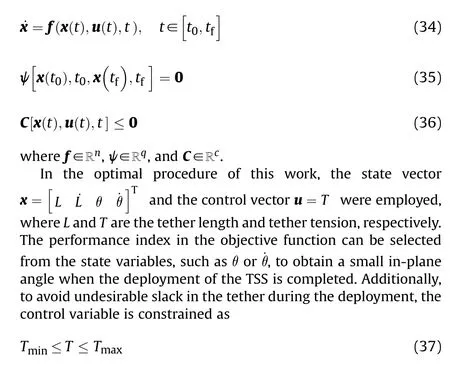
where Tand Tare the minimum and maximum tether tension.
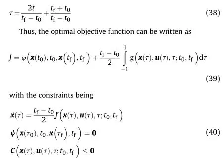
The time interval associated with the Gaussian pseudo-spectral method should be transformed from[t,t]into[-1,1]because a fixed time interval is necessary.This can be achieved using the af fine transformation
Herein,Lagrange interpolating polynomials are employed to approximate the state variables by using a set of N+1 support points,τ,τ,…,τ,τ∈[-1,1].The state variables can be approximated as

where X(τ)is a polynomial approximation of order N+1 and L(τ)is the Lagrange interpolating polynomial.
The state at the final time,X,can be included in the NLP discretization by using a Gauss quadrature:

where wis the Gauss weight,τis the Legendre-Gauss point,τ=-1 andτ=1.
The derivative of the states can be obtained by differentiating the interpolating polynomial with respect to time:

Similarly,an N th-order Lagrange interpolating polynomial can be employed to approximate the control variables,the detailed derivation can be seen in literature[33].Lastly,the objective function can be approximated using a Gauss quadrature as
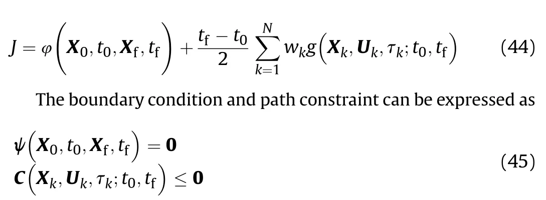
Clearly,the approximation involving Lagrange polynomials can be used to transform the problem of optimal control into an NLP problem.For a prede fined objective function for the optimal procedure and the constraint conditions,the optimal deployment velocity of the tether can be obtained.
5.Dynamic simulation of TSS
5.1.Veri fication of dynamic model
This section discusses the validation of the effectiveness of the ANCF-ALE-based dynamic model for a TSS,developed in the orbital coordinate frame.For the validation,the results derived from the dumbbell model[36]and analytical model[37]were compared with the numerical results obtained using the ANCF-ALE-based dynamic model.The formulation of the dumbbell model is expressed as

5.1.1.Veri fication without considering tether tension
For the validation of the accuracy of the dynamic model of a TSS developed in the orbital coordinate frame through comparison with the analytical model,the tether tension in the dynamic model was ignored.The relative distance and the in-plane angle of the TSS predicted by the ANCF-ALE-based dynamic model were compared with those determined from the analytical and dumbbell models.
In this case,the TSS was deployed along the z axis in the orbital frame,with an initial departure velocity of 0.2 m/s and initial relative distance L.The initial relative distance between the satellites was L=0,and that for the dumbbell model was set as L=0.01 m in view of its singularity.
The relative distance between the master satellite S1 and the subsatellite S2 obtained from the aforementioned models is shown in Fig.3,in which good agreement is observed among the values of all the models,which implies that the ANCF-ALE-based dynamic model can accurately predict the motion of the satellites in the orbital coordinate frame.
Fig.4 depicts the values of the in-plane angle of the TSS obtained from the different models.Evidently,the trends of the in-plane angle derived from the analytical model and the ANCF-ALE-based dynamic model agree well,while that obtained from the dumbbell model shows a deviation around t=5685 s.
The deviation observed for the dumbbell model probably results from the singularity in the model,hence,the relative distance and in-plane angle for the initial condition L=1 m are depicted in Figs.5 and 6,respectively.In this case,both the relative distance and in-plane angle acquired from the dumbbell model show good agreement with those obtained from the ANCF-ALE-based dynamic model,unlike the in-plane angle.
These contrasting results show that the ANCF-ALE-based model of a TSS does not show any singular problem,unlike the dumbbell model.Furthermore,the former model,which considers the gravitational gradient force and Coriolis force,can precisely describe the motion of the TSS in the orbital coordinate frame.
5.1.2.Veri fication considering tether tension
This section discusses the validation of the ANCF-ALE-based dynamic model for the prediction of the tether tension.In this case,the dynamics of a TSS with a tether of constant length L=600 m in the station-keeping phase was examined.The initial values of the in-plane angle and angular velocity were set as θ=9.7and˙θ=0,respectively.
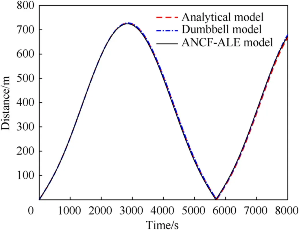
Fig.3.Distance between the satellites(L0=0).
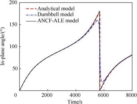
Fig.4.In-plane angle(L0=0).
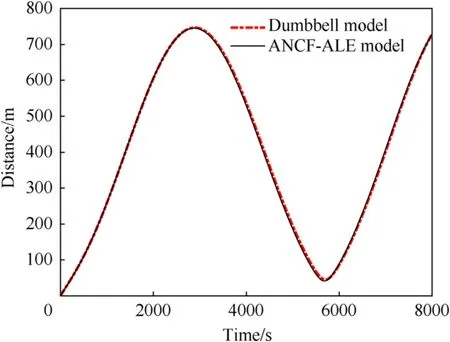
Fig.5.Distance between the satellites(L0=1).
As shown in Fig.7,the in-plane angles obtained from the dumbbell and ANCF-ALE-based dynamic models showed good agreement.Fig.8 shows the tether tension obtained from the two models,and basic agreement can be observed.In particular,for the ANCF-ALE model,an intense oscillation of the tether tension can be observed at the beginning of the station-keeping phase,and it was caused by the tether flexibility and the gravitational gradient force.Later,the tether tension decreases,resulting in a stable stretched state with a periodically varying amplitude.
Thus,unlike the dumbbell model,the ANCF-ALE-based model could predict the deformation and vibration characteristics of the flexible tether.
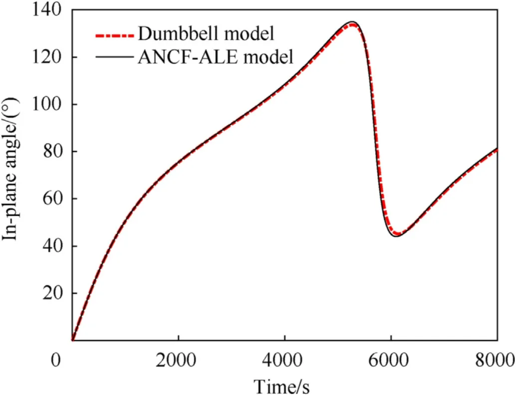
Fig.6.In-plane angle(L0=1).
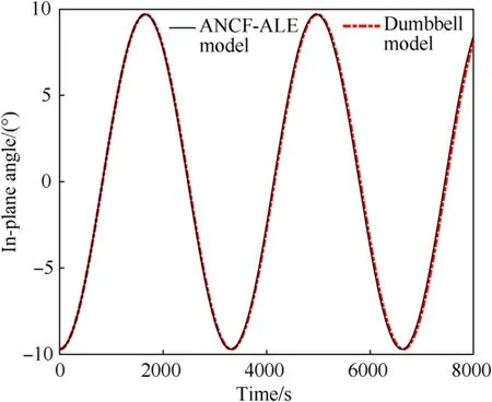
Fig.7.In-plane angle in the station-keeping phase.
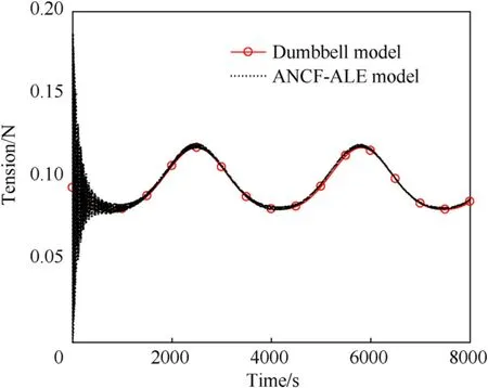
Fig.8.Tether tension in the station-keeping phase.
5.2.Dynamic analysis of TSS in deployment and station-keeping phases
In this section,the dynamic characteristics of the TSS in the deployment and station-keeping phases are analyzed.The optimal deployment velocity of the tether was acquired by using NLP.The boundary constraints and the path constraints are presented in Table 2.

Table 1 TSS deployment parameters.

Table 2 Constraints in NLP.
In practical engineering applications,the tether is deployed through the deployment mechanism.Commonly,a reliable initial deployment can be achieved provided that the initial tether tension is slightly larger than the deployment drag,which is caused by the friction effect between the tether and the pole in the deployment mechanism.If the amplitude of the initial tether tension is relatively larger and the initial deployment velocity is small,the tension of the tether is likely to have a signi ficant in fluence on the satellite motion,and even cause the rebound behavior of the tethered satellites.
Current investigations on the deployment drag usually resort to the measurement data obtained by experiment to research the relationship between the deployment drag and the tether velocity[38].The deployment drag is small in common.Therefore,researches on the deployment dynamics of the tethered satellites are inclined to neglect the friction effect and employed an unstretched state of the tether at the beginning of simulation[18,28].According to the above discussion,the deployment dynamics simulation of TSS in this paper is started under an unstretched state of the tether.
5.2.1.Dynamic analysis of TSS under an optimal deployment strategy
A dynamic simulation of the TSS in the deployment and stationkeeping phases was performed using the ANCF-ALE-based dynamic model.From the perspective of practical engineering applications,the amplitude of the in-plane swing during the station-keeping phase should be minimal.Accordingly,the objective function of the optimal procedure can be de fined as

The optimal deployment velocity of the tether was obtained using the Gaussian pseudo-spectral method,and it is shown in Fig.9.For clarity,only the variation of the tether velocity in the deployment phase is depicted;the tether velocity in the stationkeeping phase is always zero.
Curves of the relative distance between the satellites during the deployment and station-keeping phases are presented in Fig.10;curves for both the dumbbell model and ANCF-ALE-based model are shown.As evident,over the period t=0 s to 2000 s,the relative distance curves of both models agree well to a large extent.The curve for the ANCF-ALE model deviates in the period t=2000 s to 2880 s,which indicates the slackening of the tether.Furthermore,the repeated occurrence of the rebound phenomenon,re flecting intense switching of the tether between the stretched and slack states,can be observed in the station-keeping phase for the ANCF-ALE model,and it is caused by the interaction between the tether tension and gravitational gradient forces acting on the satellites.Speci fically,at the beginning of the stationkeeping phase,the rebound amplitude reaches 28 m,and it subsequently decreases to 15 m around t=8000 s under the in fluence of the damping dissipation of the tether.By contrast,the relative distance obtained from the dumbbell model was constant in the station-keeping phase.Thus,it can be concluded that the dumbbell model is incapable of predicting the rebound phenomenon during both deployment and station-keeping phases.
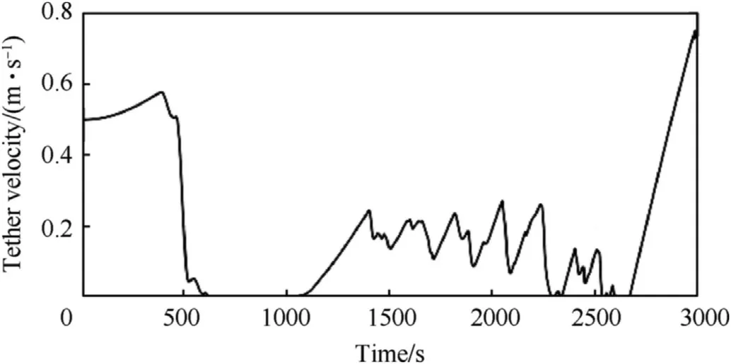
Fig.9.Optimal deployment velocity of the tether.
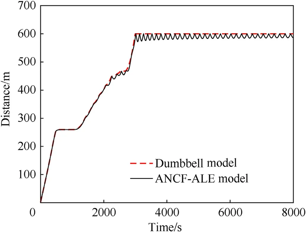
Fig.10.Relative distance between the satellites.
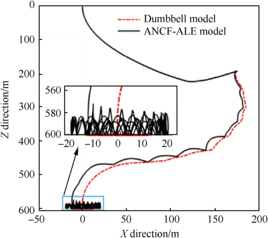
Fig.11.Motion path in the XZ plane.
The motion paths of the subsatellite relative to the master satellite are depicted in Fig.11,in which intense rebound behavior can be observed in the station-keeping phase for the ANCF-ALE model.During the deployment phase,the tether slackened and the maximal swing amplitude was approximately 180 m.The relative displacement of the subsatellite relative to the master satellite in the Z direction is mainly caused by the gravitational gradient force,and the relative displacement in the X direction is caused by the Coriolis force.
Fig.12 shows the con figuration of the TSS obtained with the ANCF-ALE model at different instants of time.The rebound phenomenon can be clearly observed.In the deployment phase of the TSS,slight slackening or rebound behavior is visible,and with the deployment of the tether and under the in fluence of gravitational gradient forces,the desired relative distance between the satellites is gradually reached and the TSS then enters the station-keeping phase.In the station-keeping phase,the switching of the tether between the stretched and slack states is observed(as shown in Figs.10-12).This repeated occurrence of the rebound phenomenon has an adverse effect on the control of the position and attitude of the TSS.
Fig.13 shows the in-plane angle obtained with different models for investigating the motion of the TSS in the orbital plane.A subtle difference between the results of the dumbbell and ANCF-ALE models can be observed after t=1335 s.In the station-keeping phase,the in-plane angle obtained from the ANCF-ALE model swings with a larger amplitude of 1.83compared with that acquired from the dumbbell model(1.16).Apart from the difference in the swing amplitude caused by the repeated occurrence of the rebound phenomenon,the swing phase angles between the two models are apparently asynchronous,which is also because of the repeated occurrence of the rebound phenomenon.
Reponses of the tether tension during the deployment and station-keeping phase are depicted in Fig.14.Apparently,the tension amplitude obtained from the ANCF-ALE model is larger than that derived from the dumbbell model,and the larger value results from the effect of the repeated occurrence of the rebound phenomenon on the tether.Owing to the flexibility of the tether and the repeated occurrence of the rebound phenomenon,the tether switches between the stretched and slack states under the in fluence of a gravitational gradient force,and accordingly,the reboundrecovery motion of the satellites affects the tether tension.During the station-keeping phase,the tension obtained from the dumbbell model basically remains unchanged because the flexibility of the tether is ignored.By contrast,the tension response obtained from the ANCF-ALE model oscillates intensively from the peak value to zero,and the peak value is gradually attenuated.The attenuation is due to the energy dissipation caused by the damping of the tether.Thus,compared with the dumbbell model,the ANCF-ALE model,which considers the flexibility and length variation of the tether,can accurately predict the in fluence of the rebound behavior on the tether tension and is therefore more suitable for engineering applications.
Furthermore,it is noteworthy that the amplitude of the tether tension increases suddenly at t=3000 s in Fig.14,which is probably caused by the rapid decrease in the tether velocity before the tether's deployment is complete.A similar oscillation appeared in the period t=1500 s to 3000 s.It can be inferred from Fig.9 that the variation rate of the tether velocity in fluences the tether tension.From this perspective,an improved optimal deployment strategy is proposed in the next section to eliminate the repeated occurrence of the rebound phenomenon.
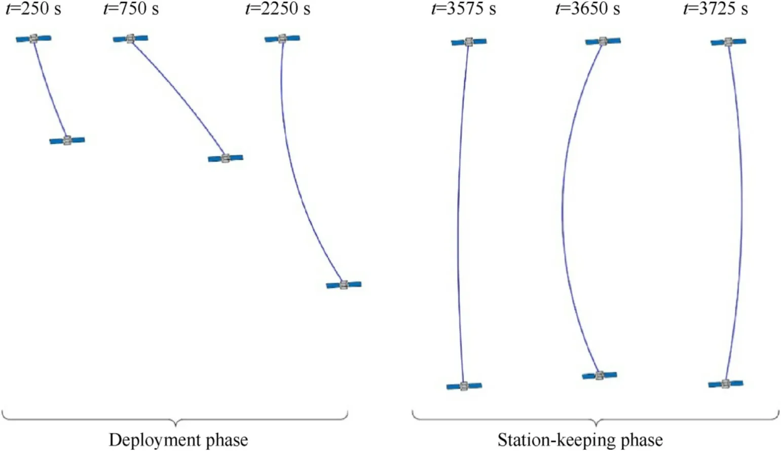
Fig.12.Con f iguration of the TSS in the deployment and station-keeping phases.
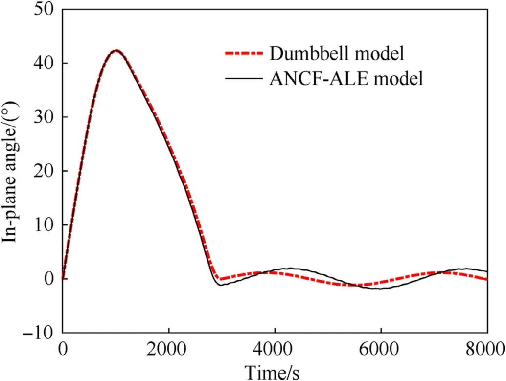
Fig.13.In-plane angle.
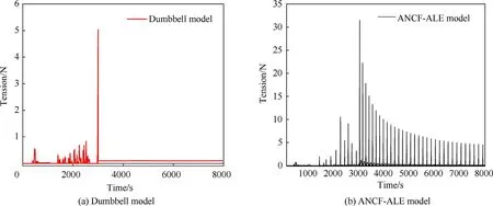
Fig.14.Tether tension.
5.2.2.Dynamic analysis of TSS under an improved optimal deployment strategy
According to the analysis above,the improper variation rate of the tether velocity induces the rebound behavior of the TSS during the deployment and station-keeping phases.Therefore,this section presents an improved deployment velocity of the tether to eliminate the rebound phenomenon.Toward this end,the objective function in Eq.(47)in the optimal procedure can be improved as follows to limit the in-plane angle and the acceleration of the tether deployment:

The improved objective function leads to an improved optimal deployment velocity,shown in Fig.15,that shows a smoother variation of the tether velocity compared with the optimal deployment velocity in Fig.9.
Fig.16 shows the relative distance between the satellites after the deployment velocity of the tether is improved.As expected,a smoother variation of the relative distance compared with that in Fig.10 can be observed,which implies that there is no repetition of the rebound phenomenon in the deployment and station-keeping phases.
The relative motion path of the satellites for the improved optimal deployment velocity is depicted in Fig.17,in which the swing amplitude during the deployment phase approaches 230 m.Compared with the motion path in Fig.11,the rebound behavior is completely eliminated.Evidently,a smooth deployment can be guaranteed with the consideration of the tether acceleration in the optimal procedure.
Fig.18 shows the con figuration of the TSS for the improved deployment strategy.Apparently,bending deformation is almost absent in the tether during the deployment and station-keeping phases compared with the con figuration of the TSS in Fig.12,which implies that the tether remains in the stretched state and the stable deployment of the TSS is easier to achieve because there is no impact force induced by the rebound behavior.
The value of the in-plane angle for the improved case is shown in Fig.19.The swing amplitude in the station-keeping phase decreases following the consideration of the variation rate of the deployment velocity in the optimal procedure.Furthermore,while there is a subtle difference between the in-plane angles obtained from the dumbbell and ANCF-ALE models because of the in fluence of the tether flexibility,the deviation value is apparently smaller than that in Fig.13 because the deployment process becomes more stable after the deployment strategy is improved.
The tether tension under the improved deployment strategy is shown in Fig.20.The tension amplitude in this case is rather small and is above zero throughout the deployment and station-keeping phases,which indicates that the tether is in the stretched state and there is no rebound phenomenon.Additionally,the values of tether tension acquired from the dumbbell and ANCF-ALE models are basically consistent with each other,the main difference being in the beginning stage of the station-keeping phase.The tether tension obtained from the dumbbell model exhibits a sudden drop from 0.168 N to 0.09 N around t=3000 s and then remains in a stable state,while the tether tension obtained from the ANCF-ALE model drops to 0.05 N and then oscillates until a stable state is reached after 30 s;the oscillation in the latter model is related to the tether flexibility.Thus,dynamic changes in the tether tension can be more accurately predicted by the ANCF-ALE model.
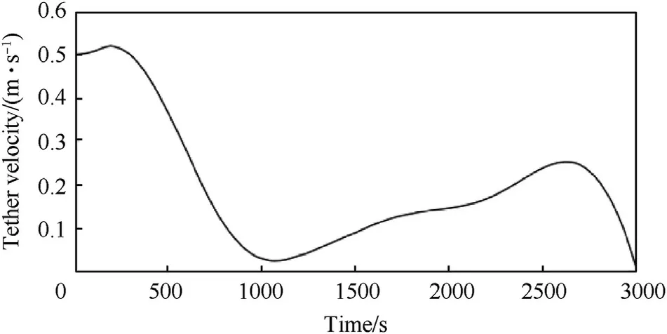
Fig.15.Improved optimal deployment velocity of tether.
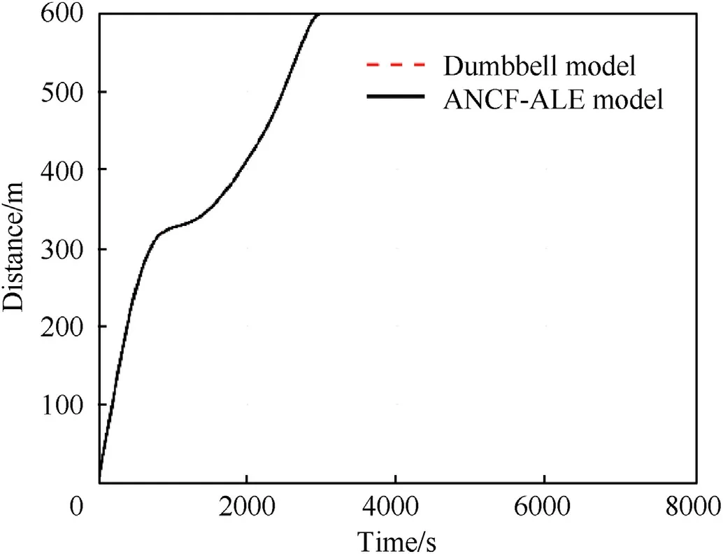
Fig.16.Improved relative distance.
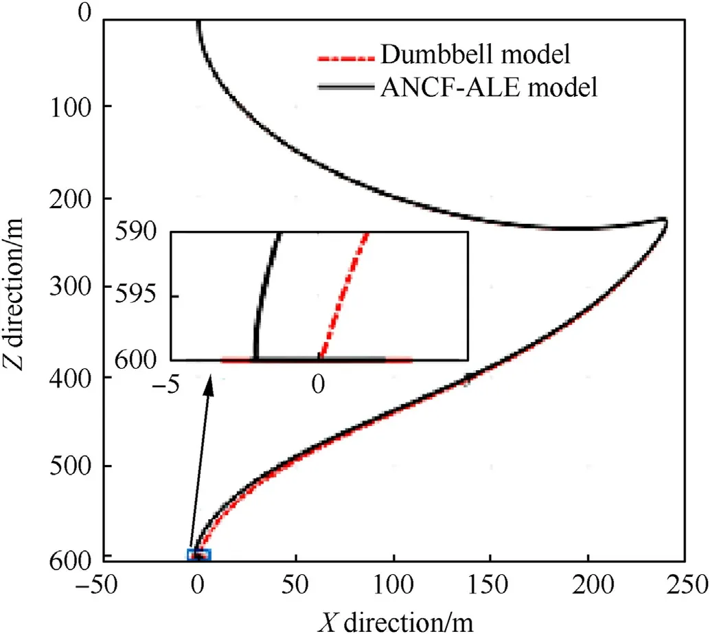
Fig.17.Improved motion path.
In conclusion,owing to the consideration of the tether flexibility,gravitational gradient force,and Coriolis force in the ANCFALE based dynamic model,the repeated occurrence of the rebound phenomenon induced by an improper deployment strategy can be captured,unlike the dumbbell model.The rebound behavior is completely eliminated when the variation rate of the tether velocity is considered in the deployment strategy,and the desired dynamic properties of the TSS,such as the stable deployment of the tether and small amplitude of the in-plane angle,are achieved.Therefore,for the reliable deployment and sophisticated dynamics prediction of the TSS,the more elaborate ANCF-ALEbased dynamic model should be used.
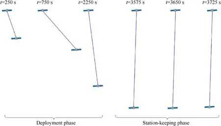
Fig.18.Con figuration of the TSS for the improved deployment strategy.
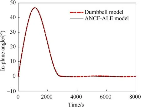
Fig.19.Improved in-plane angle.
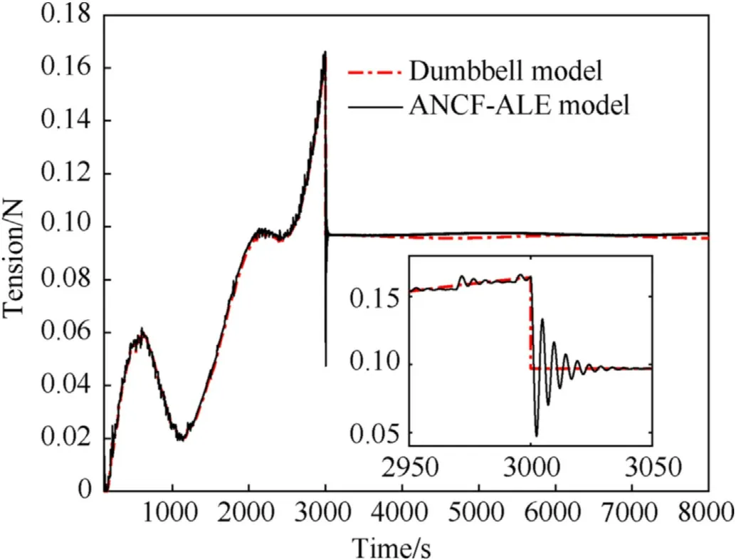
Fig.20.Improved tether tension.
5.3.Dynamic analysis of TSS considering the effect of tether deployment on the attitudes of satellites
In the analysis above,the boundary nodes of the tether are attached to the mass center of the satellites,namelyΔr=0.In this case,the attitudes of satellites will not be affected by the tether deployment.To investigate the effect of tether deployment on the attitudes of satellites,an additional simulation on the deployment and station-keeping phases in the case ofΔr≠0 is implemented.Herein the position vector of the attached points in the local reference frame of the satellites are set asΔr=[0 0 0.2]and Δr= [0 0 -0.2],and the other parameters remain unchanged.
Figs.21 and 22 show the attitude variations of the master satellite and subsatellite under the optimal deployment strategy and the improved deployment strategy,respectively.In order to analyze the in fluence of tether deployment on satellite attitude under different deployment strategies,the attitudes of satellites are not controlled in this simulation.As can be seen from Fig.21 and Fig.22(a),in the case of optimal deployment,the amplitudes of attitude motions of the two satellites exhibit rapid augments in the deployment phase,and the satellites experience intense tumbling motions in the station-keeping phase.Therefore,the rebound behavior will induce undesired tumbling motion of the satellite attitude and is fatal to the smooth deployment of tethered satellites.By contrast,moderate variations in the attitudes of the two satellites can be observed from Fig.21 and Fig.22(b),in which periodical oscillations are manifested.The amplitudes of the attitude motions under improved deployment are much smaller than those under optimal deployment,which is more conducive to the smooth deployment of the tethered satellites.
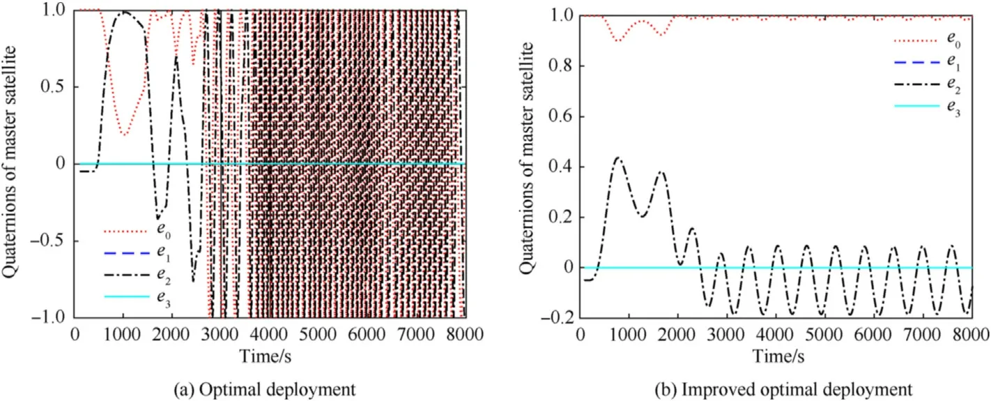
Fig.21.Quaternions of master satellite under different deployment strategies.
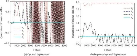
Fig.22.Quaternions of subsatellite under different deployment strategies.
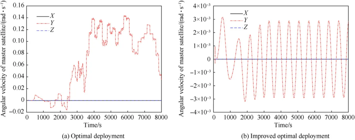
Fig.23.Angular velocity of master satellite under different deployment strategies.
Furthermore,angular velocities of the satellites expressed in the orbital frame under the optimal deployment strategy and the improved deployment strategy are illustrated in Figs.23 and 24.Obviously,the improper optimal deployment strategy will exert an intense effect on the angular velocities of the satellites,which causes a numerous augment in the amplitude of attitude motion.In contrast,small and periodical oscillations of the angular velocities can be observed in the case of improved deployment.Comparing Figs.23 and 24,it can be seen that the angular velocities of the master satellite and the subsatellite are similar under the improved deployment strategy,but they are quite different under the optimal deployment strategy.This is because the rebound behavior makes the tether switch between the stretched and slack states,which leads to a large difference in the force of the tether on the two satellites.
To investigate the effect induced by the offset of attached point Δron the dynamic behavior of TSS in deployment and stationkeeping phases,Fig.25 displays the relative motion of the satellites under the optimal deployment and improved deployment.It can be seen that the offset of the attached point has little in fluence on the relative motion path when the improved deployment strategy is applied,as can be seen in Fig.25(b).Whereas,there is a deviation emerged in the station-keeping phase under the optimal deployment,as shown in Fig.25(a).
In conclusion,the rebound behavior of the tethered satellite caused by improper deployment strategy will arouse intense oscillation of attitude in the deployment and station-keeping phases.In addition,the offset of attached point relative to the mass center of the satellite has a great in fluence on the attitude of the satellite,but has little in fluence on the relative motion path of the tethered satellites.
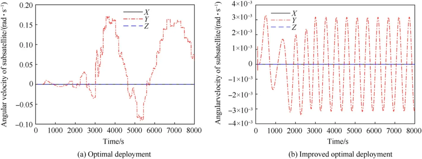
Fig.24.Angular velocity of subsatellite under different deployment strategies.
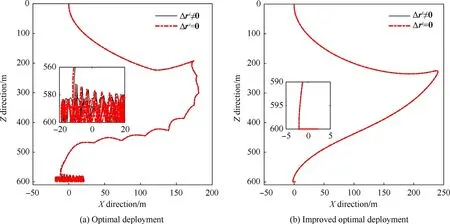
Fig.25.Relative motion path under different deployment strategies.
6.Conclusion
(1)An ANCF-ALE-based dynamic model that considers the gravitational gradient force and Coriolis force was developed in the orbital coordinate frame,and it could describe the flexibility and length variation of the tether.Veri fication of the dynamic model showed that it could predict the tether tension more precisely compared with the traditional dumbbell model.
(2)An optimal deployment velocity of the tether is presented using an optimal procedure by considering the variation rates of the in-plane angle and angular velocity in the objective function.The undesired rebound phenomenon,caused by the tether flexibility and the orbital environment effect,was observed in the deployment and station-keeping phases when using the improper deployment velocity;the phenomenon cannot be predicted by the dumbbell model.It is shown that the tether undergoes switching between the stretched and slack states in the rebound phenomenon,which in fluences the tether tension and the in-plane angle through the phase angle and amplitude,resulting in the inplane angle not meeting the expected value.
(3)Based on the observations that the variation rate of the tether velocity in fluences the tether tension signi ficantly,an improved deployment strategy,which is devised by additionally taking the variation rate of the tether velocity into account in the objective function,is proposed to obtain an improved optimal deployment velocity.Simulation based on the improved optimal deployment velocity showed that the repeated rebound phenomenon was eliminated completely and smooth deployment as well as a stable state of the station-keeping process were achieved.Additionally,the amplitude of the in-plane angle in the station-keeping phase was smaller than that in the unimproved case.The more elaborate ANCF-ALE-based dynamic model is proposed for use in the design phase of the TSS,in order to provide precise dynamics predictions and to design a reliable deployment strategy.
(4)The rebound behavior caused by the improper optimal deployment strategy may induce the tumbling attitude motion of the satellite when the attached point of the tether deviates from the mass center of the satellite,which implies the attitude motion of the satellite is susceptible to the deployment strategy.By contrast,the improved deployment strategy shows a moderate attitude motion in the deployment phase,and a small periodical oscillation of attitude in the station-keeping phase.Obviously,the improved deployment strategy is more conducive to smooth deployment and attitude stability control of the tethered satellites.
The authors declare that they have no known competing financial interests or personal relationships that could have appeared to in fluence the work reported in this paper.
This project was supported by the Natural Science Foundation of Shaanxi Province,China(2020JQ-288),Science and Technology on Space Intelligent Control Laboratory,China(HTKJ2019KL502016),China Scholarship Council(201806120093),and National Natural Science Foundation of China(61903289).
杂志排行
Defence Technology的其它文章
- High explosive unexploded ordnance neutralization-Tallboy air bomb case study
- Finite element analysis of functionally graded sandwich plates with porosity via a new hyperbolic shear deformation theory
- Investigation on the penetration of jacketed rods with striking velocities of 0.9-3.3 km/s into semi-in finite targets
- The effect of strain rate on compressive behavior and failure mechanism of CMDB propellant
- Adaptive target and jamming recognition for the pulse doppler radar fuze based on a time-frequency joint feature and an online-updated naive bayesian classi fier with minimal risk
- In fluence of metal/composite interface on the damage behavior and energy absorption mechanisms of FMLs against projectile impact
