Leap trajectory tracking control based on sliding mode theory for hypersonic gliding vehicle
2022-03-23KaiANZhenyunGUOWeiHUANGXiaopingXU
Kai AN ,Zhen-yun GUO ,Wei HUANG✉ ,Xiao-ping XU
1Science and Technology on Scramjet Laboratory,College of Aerospace Science and Engineering,National University of Defense Technology,Changsha 410073,China
2Beijing Interdisciplinary Center,National University of Defense Technology,Beijing 100101,China
Abstract:The aim of this study was to develop robust tracking control schemes for the 3D leap trajectory of hypersonic gliding vehicles using sliding mode theory.A predictor-corrector guidance method was applied to the generation of the reference trajectory,and drag acceleration was selected as the profile of reference tracking.A combined super-twisting sliding mode controller (CST-SMC) is proposed to decrease the tracking error and guarantee the tracking performance in the presence of system nonlinearities compared to three other common controllers:the linear sliding mode controller (L-SMC),global fast terminal sliding mode controller (GFT-SMC),and super-twisting sliding mode controller (ST-SMC).By using the developed controller,the system state of a second-order drag acceleration tracking error system can approach the global fast terminal sliding manifold in finite time.By using the Lyapunov approach,sufficient conditions are deduced to ensure that the tracking performance is obtained for a closed-loop system.Furthermore,we show that the controller is robust to initial uncertain parameters and other perturbations,as validated by simulation results with appropriate gains.
Key words:Predictor-corrector guidance;Drag tracking;Sliding mode control(SMC);Super twisting control
1 Introduction
Hypersonic vehicles have become a hot research field in recent years (Chen et al.,2020,2021),and their superior maneuverability and penetration will enable great changes in future military combat.However,due to their complex flight environment,strict parameter uncertainty,and strong model nonlinearity,the design of their control systems has become a very challenging research topic.A superior control system is vital for a safe re-entry flight of hypersonic vehicles.To ensure stable flight under complex constraint conditions,the control system must have a rapid response speed and disturbance rejection performance.Hypersonic vehicle control problems are generally divided into two types:trajectory tracking problems and attitude control problems (An et al.,2020).The control of trajectory tracking is the main focus of this paper.Before studying the controller,the desired trajectory is obtained using optimization algorithms,guidance algorithms or path programming methods.For hypersonic gliding vehicles,there are generally two kinds of desired trajectory:quasi equilibrium reentry trajectories and skipping re-entry trajectories(also known as leap re-entry trajectories).A quasi equilibrium trajectory is smooth and stable without large oscillations,which facilitates better track control and precision (Xu et al.,2012).Skipping gliding flight is generally applied to long range missions,which have serious trajectory oscillation amplitudes,wide flight space,and rapid state change (Wen et al.,2014).Thus,a skipping trajectory requires higher accuracy and robustness in the design of the controller.Since Sänger et al.(1952)first introduced the conceptual scheme,the skipping gliding trajectory has been continuously studied and developed into the“Tsien H.S.trajectory” by Tsien and others (Tsien et al.,1952).After that,the skipping re-entry trajectory of aerospace vehicles(ASVs)has been widely and deeply explored by a large number of scholars(Harpold and Graves Jr,1979;Li et al.,2015;Zhao et al.,2019).In this paper,the challenging skipping trajectory is considered as the reference trajectory for controllers.
Then,a specific controller will be selected to guide the hypersonic vehicle tracking the reference states.Generally,the altitude and velocity sub-systems are constructed as the reference states in the longitudinal plane (Fiorentini et al.,2009;Liu et al.,2015;Zong et al.,2015).However,a drag-based tracking strategy is a typical acceleration guidance method for shuttle entry guidance,and has proved very effective for entry missions(Zhao et al.,2016).Du et al.(2015)proposed a drag-vs-energy profile based on nonlinear model predictive control in which the drag acceleration was considered in the optimization performance index for the entry guidance problem.Zhang et al.(2016)proposed a three-dimensional acceleration profile (TDAP) planner concept that extended the traditional drag planning approach into a 3D drag space.Fu et al.(2021) also designed a drag accelerationenergy profile for generating entry landing footprints.Thus,drag acceleration has been used extensively as the tracking profile in designing standard controllers.
Currently,the conventional control approaches applied in hypersonic vehicles include linear quadratic regulator (LQR) (Lu and Zhou,2017),feedback linearization control(An et al.,2016),proportional,integral,and derivative(PID)control(Zhao and Li,2020),fuzzy control (Wu et al.,2017),and back-stepping control (Farrell et al.,2005).Furthermore,sliding mode variable structure control(VSC)shows superior performance in terms of the uncertainty of the system,as a special nonlinear control approach.Utkin (1977)first proposed the method which has been greatly developed in the last 30 years.Research on VSC has focused mainly on the sliding mode surface and reaching law.The sliding mode surface determines the convergence performance of the system,and the reaching law settles the convergence mode.The classic linear sliding hyperplane is generally chosen,where the error system asymptotically converges to zero and the convergence speed can be adjusted by some coefficients.Nevertheless,the system error will not converge to zero in finite time.Yu and Man (2009) designed a novel global fast terminal sliding mode (GFT-SM) to address the poor convergence of the nonlinear sliding mode compared with the linear sliding mode (L-SM)when the system states approached equilibrium in the traditional terminal sliding mode controller (T-SMC).The GFT-SM combines the advantages of the T-SMC and the L-SM controller (L-SMC) so that fast transient convergence can be obtained both at a distance from,and within close range of,the equilibrium.Truong et al.(2021) proposed an integral GFT-SM surface to improve the dynamic performance of the robotic manipulators compared with the terminal sliding mode (T-SM) surface.The GFT-SM controller(GFT-SMC)was also applied in the acceleration autopilot design of the skid-to-turn (STT) nonlinear timevarying missile model (Awad and Wang,2016).Xiu and Guo (2018) used the quick reaching characteristics and applications of GFT-SMC to overcome the disadvantages of the conventional sliding mode reaching law.So,the GFT-SMC has been developed to improve its performance and has been used in a wide range of applications.
The super-twisting control (STC) algorithm(Levant,1998) is one of the most powerful secondorder continuous sliding mode control algorithms,which drives the sliding variable and its derivative to zero in finite time.This algorithm is widely used to design controllers,observers,and exact differentiators with finite time convergence characteristics (Moreno and Osorio,2012).Many studies of STC algorithms have been carried out.Yan et al.(2019) proposed an adaptive super-twisting sliding mode controller(ST-SMC) method.The longitudinal model system had less chattering and better robustness.The STC worked better for the formation maneuvers of multiple robots,and dealt well with uncertainties and disturbances with unknown bounds (Zhang et al.,2020).Humaidi and Hasan (2019) presented a robust control algorithm based on an adaptive ST-SMC to guarantee the sliding surface that could reach the equilibrium point and avoid the chattering problem of a 2-DOF(degree of freedom)helicopter.
In this study,the drag acceleration control problem of a 3D trajectory was investigated using four controllers.Firstly,the L-SMC was obtained by combining the L-SM surface and exponential reaching law.Secondly,the GFT-SMC was incorporated and compared with the L-SMC in the application of hypersonic gliding vehicles.Thirdly,ST-SMC was investigated to overcome the chattering effects on controllers that lead to bad performance.Due to the asymptotic convergence of L-SMC and the bad chattering attenuation of GFT-SMC,a novel combined supertwisting sliding mode controller (CST-SMC) is proposed for guaranteeing that the system can precisely track the reference trajectory.The major contributions of this study are as follows:
1.We consider and deduce a dynamic system of drag tracking error with 3 DOFs.
2.A CST-SMC approach is proposed to improve tracking performance in the total time series compared with the three traditional sliding mode control methods.
3.Generally,in the process of controller performance verification,the system response under various uncertain disturbances (such as parameter perturbation,state error,and environmental disturbance) can best reflect the quality of the controller design and its antiinterference ability.Thus,we discuss the robustness of CST-SMC under parameter perturbation and initial state measurement errors,and verify its effectiveness.
This paper is organized as follows.In Section 2,we describe the generation of the reference trajectory using a predictor-corrector algorithm.In Section 3,we formulate the second-order drag acceleration tracking error system model.Then,in Section 4,we describe the four controllers.Finally,we report the results of the simulation in Section 5.
2 Flight modeling and reference trajectory generation
2.1 Flight modeling
Considering the curvature of the earth and the ground inertial coordinate system,the 3D dynamics of a hypersonic vehicle during the re-entry phase can be precisely described by(Lu,2014):
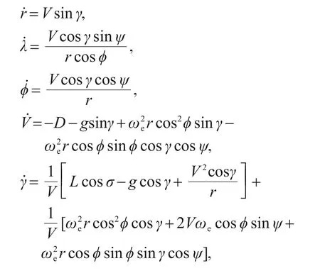
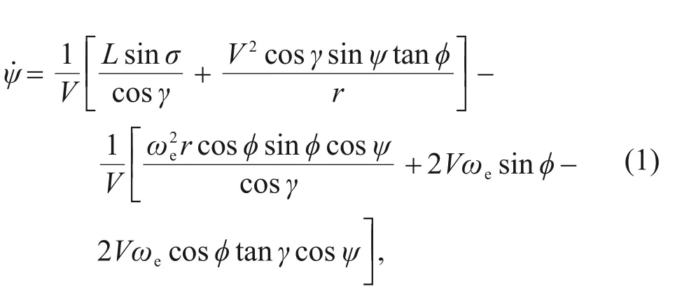
whererdescribes the relative distance from the vehicle to the center of the earth,λandφrepresent the longitude and latitude,respectively,Vis the flight speed,gis the gravitational acceleration,andγis the flight path angle.The azimuthψis defined as the angle of turning,measured clockwise from the local north.σis the control variable that controls the flight direction in 3D space,andωeis a constant representing the angular velocity of the earth.The lift accelerationL=CLρV2S/(2m)and drag accelerationD=CDρV2S/(2m)determine the comprehensive flight capability of the vehicle,wheremis the mass of vehicle,Sis the area of vehicle,CLandCDdenote the lift coefficient and drag coefficient,respectively,ρ=ρ0exp[-(r-Re)/hs] is the atmospheric density,ρ0is standard atmospheric density,Reis the earth radius,andhsis the atmospheric parameter.
2.2 Reference trajectory generation
Considering the trajectory tracking problem,generally,the guidance law or the optimization method is adopted in offline/online trajectory programming in advance for a reference path.Then,the controller is designed to control the vehicle to follow the reference states strictly.Because the predictor-corrector guidance approach has incomparable advantages in online rapid trajectory planning,in this study,this approach was used for a desired,feasible reference that satisfied constraints.The main steps of the predictor-corrector algorithm are as follows(Lu,2014).
Step 1:Select the angle of attack expressed in the given function and the bank angle which need to be calculated iteratively as the control variables.In every time step,the dynamic equations (Eq.(1)) are integrated to obtain the actual flight distance information from the current state of the vehicle to the terminal conditions,which is called the prediction process.
Step 2:The space motion is divided into two planes because the amplitude and sign of the bank angle need to be solved separately.In the longitudinal plane,the absolute value of the bank angle will be updated by calculating the difference between the predicted range and the actual range.Meanwhile,constructing the azimuth error corridor for the sign of the bank angle in the lateral plane,the judgment conditions are calculated by the current azimuth and the line-of-sight angle between the vehicle and the target.The final limited re-entry trajectory can be solved when the obtained bank angle is output to the dynamic equation (Eq.(1)).This step is called the rectification process.
Through the prediction process and the rectification process,a satisfactory re-entry leap trajectory under the complex constraint conditions can be solved,and was taken as the reference trajectory of the tracking control in this study.The detailed procedures of this algorithm are described in the following parts.
2.2.1 Constraints transformation
First,the original dynamic equation with timetas the independent variable is transformed into the new model with energyeas the independent variable.The energy expression is defined as

whereμis the constant of earth gravitation.The new model can be obtained by combining Eqs.(1)and(3),which can be rewritten as

wherexis the reduced-order state vector,x0is the initial condition of the state vector,ande0is the initial energy.
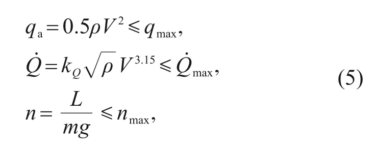
In the re-entry phase,the vehicle is constrained by several typical inequalities (Eq.(5)) such as path constraints,which include the heating rate,overloadn,and dynamic pressureqa.whereqmaxis the dynamic-pressure limit,is the heating-rate limit,kQ=9.4369×10-5×3,andnmaxis the overload limit.Several appropriate terminal conditions,such as terminal velocity limitVTAEM,terminal altitude limitHTAEM,terminal bank angle limitσTAEM,and terminal flight distance limitSTAEM,also need to be considered (Eq.(6)).It should be pointed out that the subscript TAEM represents terminal area energy management.All the above constraints need to be converted to the range of the bank angle related to velocity.
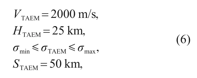
whereσmaxandσminrepresent the maximum and minimum values forσ,respectively.The relationship between flight altitudeHand flight speedVcan be obtained from Eq.(5):

whereHQ,Hq,andHnare the altitude constraints related to,qmax,andnmax,respectively.Furthermore,the altitude constraints are converted to the ranges of the bank angle amplitudes (σQ,σn,andσq) respectively(Eq.(9)) according to the quasi-equilibrium glide condition(Eq.(8)):

2.2.2 Longitudinal guidance
Step 1:To meet the terminal range-to-go,the angle of attackα0and bank angle magnitude|σ(e) |profiles are designed as linear piecewise functions,such as Eqs.(10)and(11):
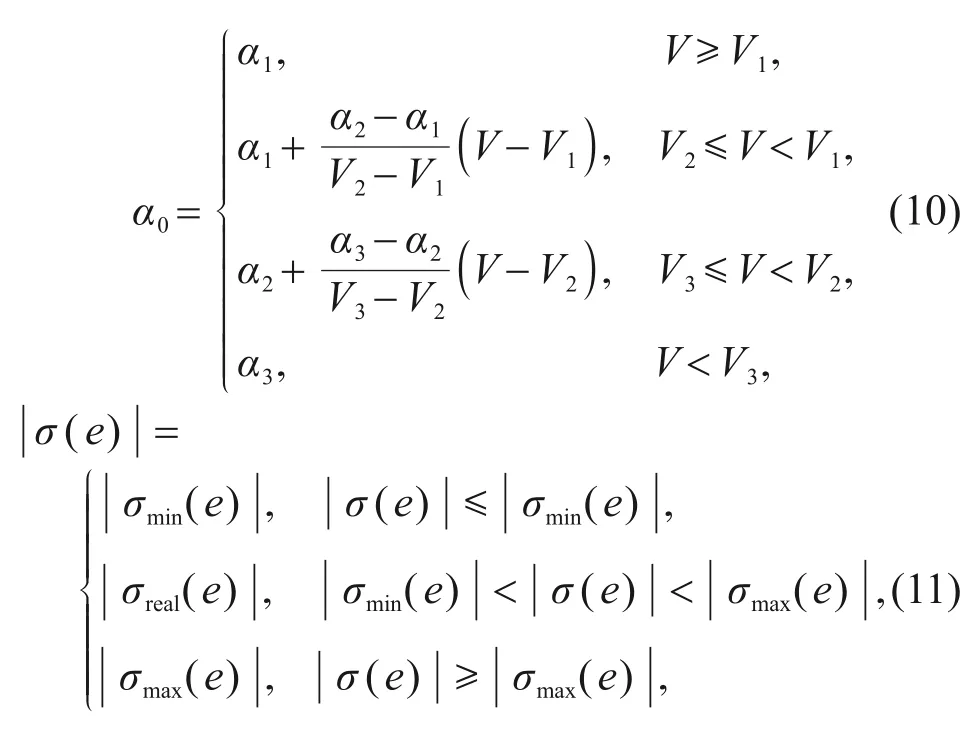
whereα1,α2,andα3are the segmented node variables of the angle of attack model,and they are fixed when the angle of attack model is given.V1,V2,andV3are the corresponding speed node variables.σrealis an intermediate variable need to be found.The expression of |σ(e) | is

whereefis the final energy condition,erealis the current energy,andσfis a sufficient constant.
Step 2:In each guidance cycle,the feasible value ofσrealis solved so that the vehicle can be steered from the current states to the final energy conditionsef,and the entry trajectory needs to satisfy the terminal rangeto-go constraints:

whereεis a positive constant,stogois the range-to-go variable,andrepresents the desired range-to-go,which is defined as the length of the great circle from the current location to the target:

whereλfandφfare the target longitude and latitude,respectively.The updated scheme is approximated by a secant method,wherez(σ)=stogo(ef)-,andkσis a positive constant that controls the convergence rate:

If the criterion condition(Eq.(13))is not met,the corrector step seeks to updateσreal(e)as the next iterationby the secant method using the current energyereal,thekth iterationand the(k-1)th iteration.
2.2.3 Lateral guidance
Afterσrealhas been found,the sign ofσ(e) is determined by a classic bank-reversal logic in the lateral guidance plane.Assuming that the current longitude isλcur,the line-of-sight angleψcurcan be expressed as

Define the current heading offset Δψas

whereψVis the actual heading angle.
A velocity-dependent interval segmentation is designed in the form of a piecewise function,where Δψ1and Δψ2are the segmented node variables,and so areV11andV22.

Once Δψincreases from one direction and exceeds its upper bound Δψupor lower bound Δψdown,the bank angle is commanded to change the sign,otherwise,it will remain.

where sgn(σ)is the sign ofσ.
Through the above algorithm,the components of the reference states and control curves are obtained(Fig.1).

Fig.1 Components of reference states and control profiles:(a) reference altitude profile;(b) reference velocity profile;(c)reference drag profile;(d)reference control profile
3 Drag tracking problem formulation
Commonly,the design of a tracking controller for a hypersonic vehicle usually focuses on the longitudinal and lateral plane motions.However,there are additional effects that need to be considered in controller design if the dynamic formula is decoupled into the longitudinal plane and the lateral plane.On the one hand,because coupling factors exist in the longitudinal and lateral channels,especially in the process of numerical calculation,the accumulation of errors and complex disturbance terms will increase the complexity of controller design.Simplified dynamic models may also produce inconsistent results.On the other hand,the amount and complexity of controllers require a high computation capacity because they could increase the computational burden of the system.
The trajectory control variable isu=cosσ,and the drag accelerationDis selected as the reference tracking profile.Then,the 3D trajectory of the vehicle can be controlled.The advantages of choosing drag acceleration as the reference instruction are obvious.First and foremost,the tracking problem can be simplified as discussed above,and the drag profile can control both longitudinal and lateral plane motions.Secondly,the drag profile can determine the flight distance to a certain extent.To ensure that the lateral plane motion is close to the desired trajectory,the same strategy as used in the predictor-corrector guidance algorithm is adopted.Therefore,the aim of this study was to design a drag acceleration tracking controller to guarantee that the vehicle can track the reference drag profile rapidly and improve the robustness of the system for the 3D leap trajectory of a hypersonic gliding vehicle.
Define the drag acceleration tracking errore1as

whereDdis the desired reference drag acceleration.The drag acceleration tracking error dynamics can be obtained by taking the time derivatives of the drag acceleration error in Eq.(20),as follows:

The expression of drag acceleration is

LetBfn=be the aerodynamic coefficient,which is taken as a constant.Then,the first derivative ofDwith respect to time can be obtained from

Similarly,the second derivative ofDis

Considering the flight characteristics of a hypersonic vehicle,the second part Δf2of Eq.(24)can be ignored.Also,the flight path angle of the vehicle is always less than 5°from the reference state curves,so we have the approximations cosγ≈1 and sinγ≈γ.
Then,substituting Eqs.(23)and(24)into Eq.(21),the drag acceleration tracking error dynamic equations can be written as

where

The second-order system with respect to the drag acceleration tracking error is constructed,and the goal of controller design is to make the tracking error converge to 0 in finite time.
4 Controller design
4.1 Traditional sliding mode controllers
There are two main assessment indices of controller performance.The first includes rapidity and accuracy,which can ensure that the system reaches the reference point precisely in a limited time.The second is the robustness of the system when subjected to interference by some external disturbances.The sliding mode theory has strong adaptability in the control of nonlinear systems,and comfortably meets these two requirements with reasonable parameters.According to sliding mode theory,the sliding mode motion is usually composed of two stages:the reaching mode motion and the sliding convergence motion.The system can move towards the sliding mode surface no matter which initial state it remains in.That is,when the system reaches the surfaces=0,it has accomplished the first stage.After that,the controller will force the system to move along the sliding mode surface and converge to the equilibrium point (origin point).The sliding convergence motion is the second stage.Two kinds of sliding mode,L-SM surface and T-SM surface,show better convergence quality with a wide application range.These satisfy the reach conditions<0,s>0 or>0,s<0,and guarantee that the system can approach the equilibrium point in finite time along the sliding surface.Yet,an unknown system sliding trajectory limits the evaluation of controller performance.The sliding mode reaching laws,such as the constant velocity reaching law and exponential reaching law,provide a solution to this problem.Therefore,in the following sections we compare and discuss the abilities of the two sliding mode surfaces and two other approaches to control the leap trajectory of a hypersonic gliding vehicle.Based on the analysis of their characteristics,we propose a combined sliding mode controller to improve global tracking performance.
Note that the following lemmas are needed in the verification of control convergence.
Lemma 1Considering a nonlinear sliding mode surfaces,

whereesis the error variable,andα,β,p,andqare all constants.If the conditions=0 has been satisfied,the equilibrium point of the system is globally finite-time stable in timets:

wheretris the reach time in which the system moves from arbitrary initial states to the sliding surfaces=0.
ProofThe expression of convergence time can be obtained by solving the differential equations=0 analytically.As soon as the system reaches the sliding mode surface from any initial states,Eq.(27) can be written as
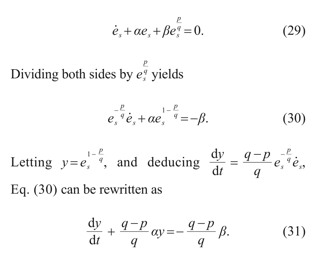
Obviously,Eq.(31) is a first-order differential equation,with the common form of

whereP(x) andQ(x) are polynomial expressions,andxrepresents the arbitrary variable.Then,the general solution is

whereCis a constant.
Substituting the terms corresponding toP(x) andQ(x)in Eq.(31)into Eq.(33),we can obtain:
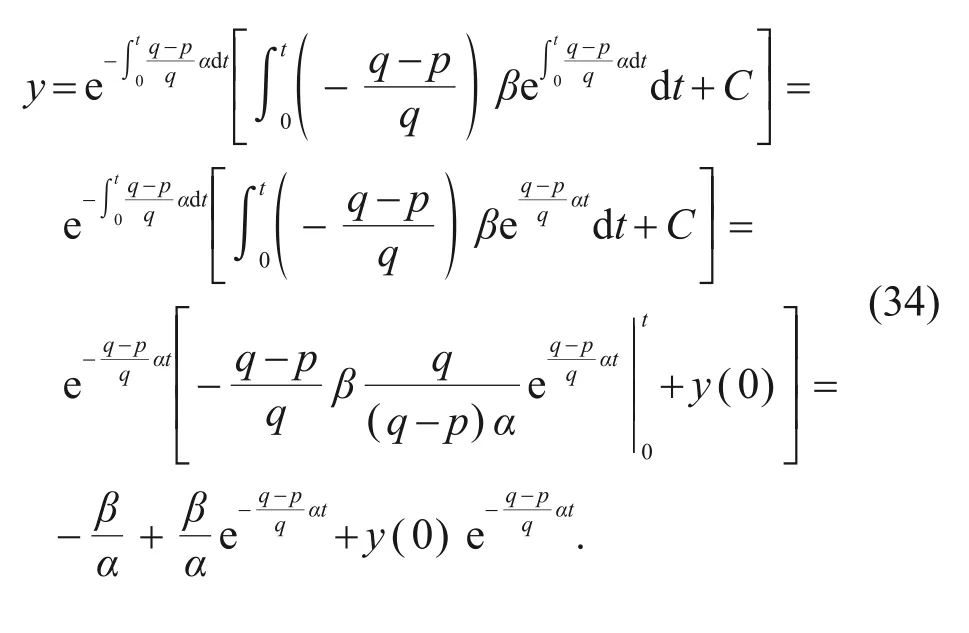
Then,fores=0,y=0,andt=ts,
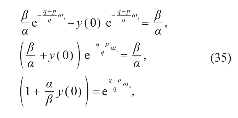
wherey(0)=es(0).Hence,the total convergence time is determined by

The system will reach the balanced states in finite time through the appropriate parametersα,β,p,andq.
Lemma 2The non-Lipschitz continuous nonlinear system is given as

wherexLis the continuous nonlinear system vector,andt0is the initial time.Suppose there exists a continuous and differentiable functionVL(xL) and real numbersαV>0 and 0 <βV<1,and the conditionsare satisfied.Then,the origin is a finite-time stable equilibrium of Eq.(37).IfTsis the settling time,then for allxLin some open neighborhood of the origin,

Oncet≥Ts,s==0.
Lemma3 For the system,

wherekx1andkx2are constants.x1,x2∈R indicates the system states are continuous.Then,the system is finite-time stable.
4.1.1 Linear sliding mode controller(L-SMC)
Let the L-SM surface be chosen in terms of drag acceleration errore1such that

wherecis a constant.
Differentiate Eq.(40),

To ensure the sliding mode surface can converge to zero in finite time,the following reaching law is considered:

whereηandksare constants.Substituting Eq.(42)into Eq.(41),the controllerucan be obtained:

Theorem 1For the dynamic model Eq.(1) of a hypersonic gliding vehicle,if the L-SM manifold is chosen as in Eq.(40),the reaching law is Eq.(42),and the continuous L-SMC is designed as Eq.(43),then the tracking errore1will converge to zero as timet→∞,and the state variables will converge to their desired values.
ProofChoose the following Lyapunov function candidateVL:

Derivate Eq.(44)using Eq.(41),

Substituting Eq.(43)into Eq.(45)yields,

Sinceη,ks>0 in Eq.(46),andis negative definite,then≤0,which implies that the system will reach the sliding mode surface in finite time.Once the conditions=0 is satisfied,the following equation can be obtained:

Solving Eq.(47)analytically,

Then,the tracing errore1will converge to zero as timet→∞with a convergence ratec.Note that the system arrives asymptotically.
4.1.2 Global fast terminal sliding mode controller(GFT-SMC)
Define the following sliding mode manifold:

The same reaching law is applied:

Then,the GFT-SMC law can be deduced from Eq.(50)and the derivative of Eq.(49):

Theorem 2For system Eq.(1) and tracking error dynamic Eq.(25) with the GFT-SM surface Eq.(49),the designed controller Eq.(51) will force the statese1ande2to converge to zero in finite time,and then the system states will be consistent with the desired states.
ProofTaking the time derivative of the surfaces,and applying the control law given by Eq.(51),we have the following deduction:

Let the Lyapunov function candidate be such that:

DifferentiatingVLwith respect to time and substituting Eq.(52)yields

It is clear from Eq.(54) thatwhenη,ks>0.Therefore,the system can reach the sliding surface in finite time under the reaching law Eq.(52).Once the system remains on the sliding mode surface,the following dynamic is guaranteed with reasonable parametersα,β,p,andq:

From Lemma 1,this dynamic ensures the finite-time convergence ofe1ande2to zero in timets.Furthermore,the system states will be consistent with the desired states.
4.1.3 Super-twisting sliding mode controller(ST-SMC)
The ST-SMC is a kind of second-order control algorithm,which differs from the exponential reaching law used in Sections 4.1.1 and 4.1.2.The algorithm consists of two parts:the discontinuous time differentiation of the sliding mode variable,and the continuous function in terms of the sliding mode variable.System chattering can be effectively suppressed by this algorithm compared with other first-order sliding mode control laws,and the robustness of traditional sliding mode controllers can be retained.
Considering the global fast terminal sliding manifold in terms ofe1ande2:

Then,the finite time ST-SMC is designed as

whereυ>0 andω>0 are constants.The reaching condition iss<0.Substituting Eqs.(56) and (57) into it yields:

Thus,the system satisfies the reaching conditions from any initial state to the surface.
Theorem 3For the dynamical vehicle model Eq.(1) and the sliding surface Eq.(56),the system tracking errors Eq.(25) will converge to zero eventually,and the vehicle will be situated at the desired point in finite time by controller Eq.(57).
Proof(1) Prove the sliding mode variableswill converge in finite time.
Taking the time derivative of Eq.(56),we can obtain:

Substituting Eq.(57)into Eq.(59),we can obtain:

According to Lemma 3,the sliding mode variables can converge to zero in finite time.
(2) Verify the convergence of the drag tracking error in finite time.
Once the system reaches the sliding mode surface,the condition will be satisfied,then

From Lemma 1,this dynamic ensures the finite-time convergence ofe1ande2to zero in timets.Furthermore,the system states will be consistent with the desired states.The proof is finished.
4.2 Combined super-twisting sliding mode controller(CST-SMC)
Considering the characteristics of the exponential reaching law and super-twisting sliding mode algorithm (see Remarks 1 and 2 for details),a novel combined finite time super-twisting sliding mode controller(CST-SMC)is designed,which also adopts the GFT-SM surface:

The CST-SMC is designed as

wherek2>0 is a constant.
Theorem 4For the hypersonic gliding vehicle dynamic system Eq.(1),the T-SM surface Eq.(62)and the CST-SMC Eq.(63) can ensure that all the states information can track the reference trajectories in finite time.
Proof(1) Prove the system error can reach the sliding manifolds=0 in finite time.
Substituting Eq.(63) into Eq.(25),we have the detailed expression:


The novel reaching law is designed as

Dividing Eq.(65)into two sub-systems,
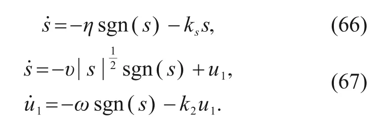
The exponential approach term=-kssin system Eq.(66) has the solutions=s(0) e-kst,which implies that progress towards the sliding surface is a gradual process and does not satisfy the condition of finitetime arrival.In this case,if a constant speed reaching term is included,the reaching speed will decrease toηas soon assis close to zero,so the finite-time arrival of the system can be guaranteed.
We discuss mainly the stability of system Eq.(67).Define a 2D vectorw:

Derivate Eq.(68) according to the property of matrix derivation:
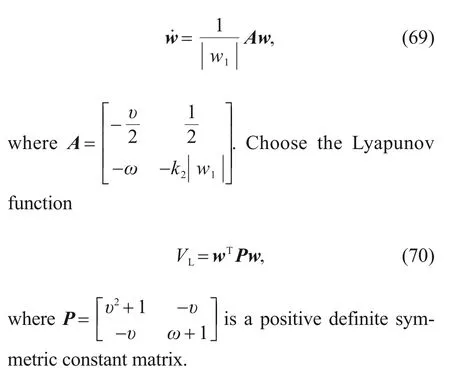

whereP,A,andQare related by

Supposeλmin(Q) is the minimum eigenvalue about matrixQ,then the following inequality holds:

Substituting Eq.(73)into Eq.(71),then

Similarly,we supposeλmin(P) andλmax(P) are the minimum eigenvalue and maximum eigenvalue about matrixP,respectively,so the inequalities can be obtained from Eq.(70):

In conclusion,we have the final expression reflecting the properties of the Lyapunov function:

According to Lemma 2,the system is finite-time stable if the parametersυ,ω,andk2satisfy the Lipschitz conditions.The convergence timeT2is

Suppose the convergence time(T1)of system Eq.(66)meets the expressionT1≤Tc(whereTcis the fixed time),and then the original system Eq.(65) has the reaching timeTr:

The system will meet the conditions=0 because of Eq.(79).
(2) Verify the drag acceleration error converges to zero in finite time.
Once the error variablese1ande2reach the sliding mode surfaces==0,Eq.(62) can be further represented as

By Lemma 1,the above system Eq.(64) will show finite-time stability to the equilibrium point.
Remark 1The GFT-SM surface has unique advantages over the L-SM surface.It can ensure that the system reaches the sliding mode surface rapidly and guides the system to converge to the origin point in finite time,compared with the asymptotic convergence of L-SM.Also,the small enough indexp/qconstricts system movement within a small neighborhood of the sliding surface.Moreover,it is more robust in response to system perturbation and disturbance.
Remark 2The reaching speed decreases gradually from a huge number when the state errors of the system are away from the surface in the exponential approach law.We know the crucial factor is the linear term.Considering the linear term in Eq.(42)can adjust the convergence rate of the system,we added a linear expression in terms ofsto the dynamic formulau1of the STC algorithm,to improve the dynamic response of the higher-order term.In addition,the ST-SMC algorithm can effectively suppress the chattering problem,so the system can quickly reach the sliding mode surface.
The control scheme adopted in this study is shown in Fig.2.After the feedback control process,the tracking state parametersr*,λ*,φ*,γ*,ψ*,andV*are finally obtained.
4.3 Parameter discussion
For the leap gliding trajectory,the reference drag trajectory is a continuous curve.However,the performance of the tracking controller varies along the entire time series.Taking GFT-SMC as an example(Fig.3),the tracking results of the middle segment are not acceptable compared to those of the initial and ending segments.The reasons are as follows:
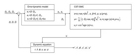
Fig.2 A block diagram of the drag tracking control problem using CST-SMC
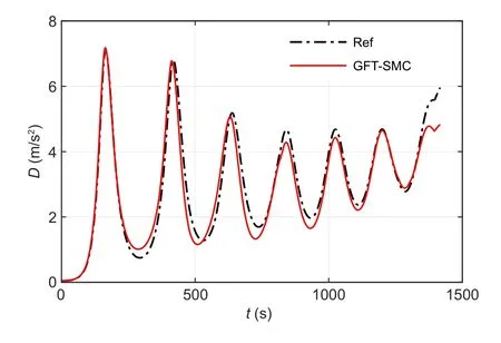
Fig.3 Drag tracking profile of GFT-SMC.Ref represents the reference drag trajectory
1.Adaptability of multi-parameters.The leap gliding flight has more severe and frequent state changes.Because the oscillation characteristics of the trajectory differ from those of cruise flight and quasi-equilibrium gliding flight,the constant gains cannot always meet the tracking requirements accurately along the total time series.Thus,adaptive parameters can be introduced to match the system changes.It is vital to determine the influence of every parameter on the system,to enable selection of feasible parameters.The parameters of controller Eq.(63) were analyzed.Increasingkscould increase the velocity approaching the sliding surface without being too large.On the contrary,the gainηof the constant approaching term=-ηsgn(s)needs to be small enough assconverges to zero in order to meet the lower terminal speed.αandβalso have clear physical meanings,which determine mainly the convergence time in different phases.If the system states are far away from the origin points,βwill play a major role in controlling convergence time,whileαworks mainly if the system nears the points.The purpose of adjustingαandβis to improve the approaching velocity as soon as possible.In the STC algorithm,parametersυandωcan influence the steady-state error and eliminate chattering.k2can change the dynamic response of higher-order terms of the system.Before the parameters are decided,the magnitude and range need to be estimated according to the error system,and then every parameter needs to be modified carefully.In this study,the piecewise function was planned to reduce the drag tracking error in the whole tracking process.
2.Different controllers perform differently in the same system.By comparing the CST-SMC with traditional controllers,the advantages of CST-SMC were highlighted.
In addition,the CST-SMC proposed here theoretically can be applied to any nonlinear system models.However,considering the different characteristics among the models,the control results may be worse than those of the classical controllers,so it is not possible to guarantee that the performance is optimal for all nonlinear models.In this study,we considered the re-entry trajectory tracking control problems for a class of hypersonic gliding vehicles.Of course,in addition to the vehicle model (CAV-H,a generic high-performance common aero vehicle) (An et al.,2020) and its reference trajectory used in the simulation,CST-SMC is commonly used for other spacecraft and equilibrium gliding trajectories (such as the Mars entry trajectory).The above parameter discussion is crucial for designing controller parameters rapidly,and provides a useful reference for development.
5 Simulation results
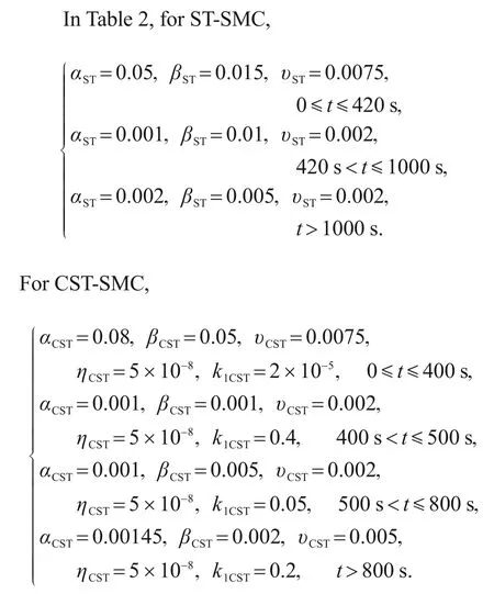
In this section,we will conduct four simulations:comparing tracking performance of the four controllers (L-SMC,GFT-SMC,ST-SMC,and CST-SMC)for a drag reference trajectory,comparing tracking performance of a PID controller and CST-SMC,verifying the robustness under the influence of parameter perturbation,and initial parameter measurement errors.The initial conditions and parameters of the controllers are shown in Tables 1 and 2,respectively.The CAV-H model was considered in the simulations.

Table 1 Initial conditions for hypersonic vehicle simulation
5.1 Case 1:simulation without parameter perturbation
With the proposed control law Eq.(63),the simulation results without parameter perturbation are shown in Fig.4.The tracking error of CST-SMC is clearly less than those of the other three controllers(Fig.4h).A superior tracking performance is obvious as the drag acceleration(Fig.4g)always moves along the desired profile,as with other longitudinal states such as altitude trajectory(Fig.4a),velocity(Fig.4c),and flight path angle(Fig.4d).The lateral state errors(Fig.4b)in the longitude-latitude plane are obvious in the process of tracking because of the poor fitting of the bank angle (Fig.4e) and azimuth (Fig.4f) profiles,but the terminal longitude error and latitude error are all less than 0.5°.This comparison of the four controllers demonstrates the superior tracking performance of the proposed method.
5.2 Case 2:simulation comparison with classical controller
As one of the most classical controllers,the PID controller has been widely applied in various control fields.In this study,we compared the CST-SMC with the PID controller,and the results are shown in Fig.5.The following conclusions can be drawn:
1.The PID controller has just three control parameters,which is convenient for adjustment,but more difficult for obtaining appropriate parameters.
2.The PID controller with constant parameters or piecewise constant parameters cannot track the reference drag curve well.The tracking errors for serious states(Figs.5a and 5b)and drag(Fig.5c)are obvious in the corresponding figures.For better control results,it is important to develop an adaptive PID controller and further consider the problem of calculation efficiency.
3.Although the expression of the CST-SMC is not as simple as that of a PID controller,it has greater control,higher control precision,and other obvious advantages.
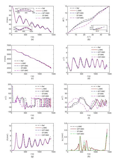
Fig.4 Comparison of simulation results of the four controllers:(a)altitude trajectory profile;(b)land trajectory profile;(c)velocity profile;(d)flight path angle profile;(e)bank angle profile;(f)azimuth angle profile;(g)drag tracking profile;(h)drag tracking error

Fig.5 Comparison of simulation results from PID and CST-SMC:(a)altitude tracking profile;(b)land trajectory tracking profile;(c)drag tracking profile;(d)drag tracking error
5.3 Case 3:simulation with parameter perturbation
Normally,the air densityρ,aerodynamic parametersBfn,and lift-to-drag ratiokL/Dwill inevitably generate parameter perturbation due to the strict flight environment and high re-entry speed.Here,we consider constant parameter perturbation and stochastic parameter perturbation to verify the robustness of the proposed controllers.The constant and random parameter settings are shown in Table 3,where rand is a random number taken from[-1,1].

Table 3 Settings of constant parameter perturbation and stochastic parameter perturbation
(A)Constant parameter perturbation
The simulation results in Fig.6 confirm that our proposed method has better tracking robustness for the reference states with constant parameter perturbation.Figs.6a,6b,and 6d show that the system has lower errors when using the CST-SMC,where theY-axis is calculated by(i=H,V,D),ande1irepresents the tracking error ofi.The land trajectory is expressed by Fig.6c,which shows the differences in the reference trajectory among all four controllers,but they all reach the terminal constraint position (50°,15°) in finite time.Note that the bank angle produces severe tracking error,and thus the land trajectory is different.
(B)Stochastic parameter perturbation
Note that the altitude error (Fig.7a) and speed error(Fig.7b)of the L-SMC and GFT-SMC are several times higher than those of the proposed CST-SMC.Fig.7d shows that,owing to the influence of stochastic parameter perturbation,the curves exhibit oscillation.Similarly,the system performs better using the CST-SMC method under stochastic parameter perturbation.
5.4 Case 4:simulation with the initial parameter measurement error influence
The settings of the initial parameter measurement errors are shown in Table 4.In setting 1,the altitudeHand velocityVsuffer a small disturbance;in setting 2,the influence of changed lateral parameters will be examined;in setting 3,all the initial states will be disturbed.
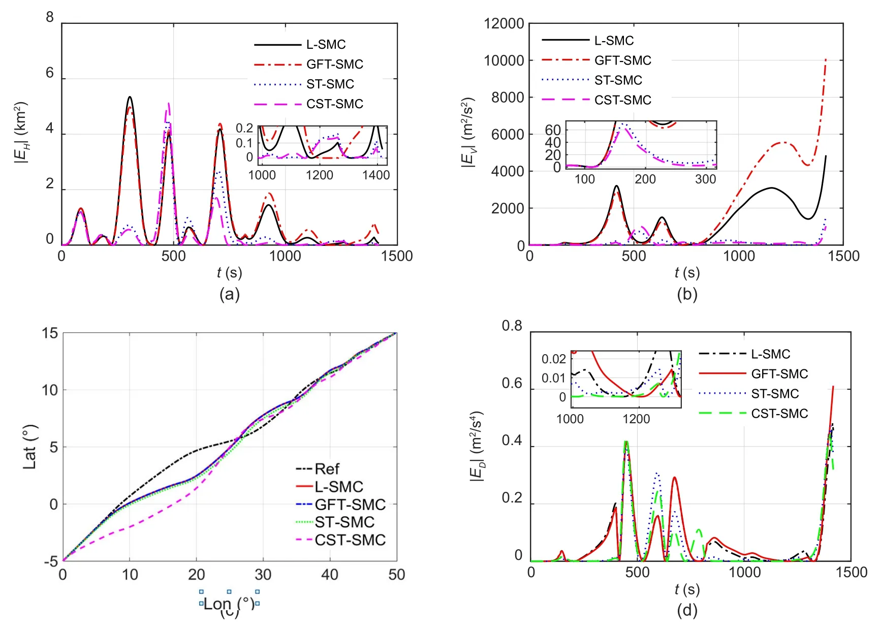
Fig.6 Tracking results with constant parameter perturbation:(a)altitude tracking error;(b)velocity tracking error;(c)land trajectory profile;(d)drag tracking error
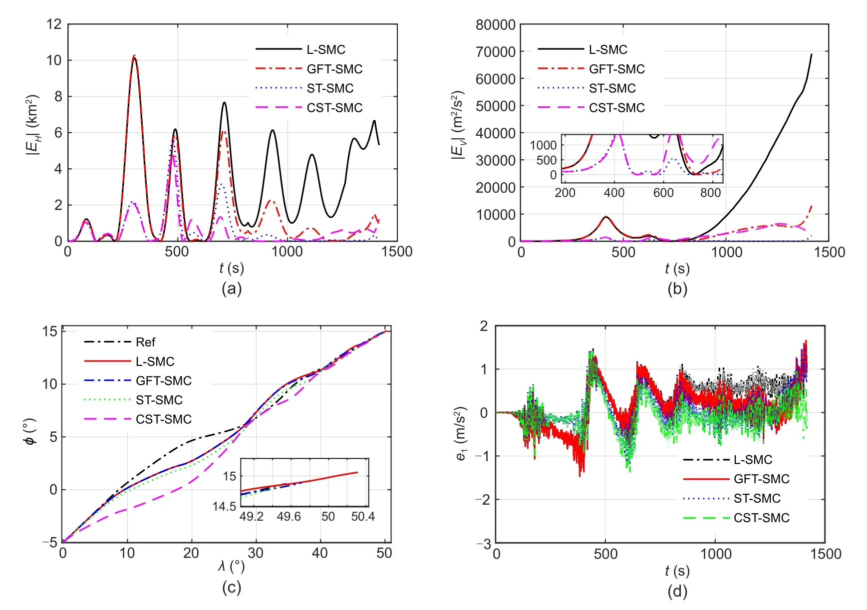
Fig.7 Tracking results with stochastic parameter perturbation:(a) altitude tracking error;(b) velocity tracking error;(c)land trajectory profile;(d)drag tracking error
From Figs.8a and 8b,the curves of setting 1 and setting 3 have obvious errors due to the initial disturbances of altitude and velocity.Fig.8c shows that the performance of our proposed controller is robust and insensitive to initial altitude and velocity measurement errors.The bank angle profile in Fig.8d satisfies the constraint scope.
Based on the simulation results of the three cases,the proposed CST-SMC can adapt to different initial parameter measurement errors and ensures that hypersonic gliding vehicles can precisely track the reference trajectory under constraints.Moreover,the CST-SMC achieves faster convergence of the sliding surface in finite time and reduces the tracking errors compared with the other three controllers.
6 Conclusions
This study was concerned with the 3D trajectory tracking problem of hypersonic gliding vehicles.The reference trajectory was obtained by the predictor-corrector guidance method.The drag acceleration was chosen as the reference profile to be tracked and the bank angle as the control variable.Then,a CST-SMC based on the T-SM surface was proposed for guaranteeing the finitetime convergence of the drag tracking error even with parameter perturbation and initial parameter measurement uncertainties.We also deduced three traditional sliding mode controllers,the L-SMC,GFT-SMC,and ST-SMC,and compared their control performance with CST-SMC in simulations.The results showed that the CST-SMC has much better tracking performance than the other three controllers in the presence of various uncertainties,and has great application potential.

Table 4 Settings of the initial parameter measurement errors
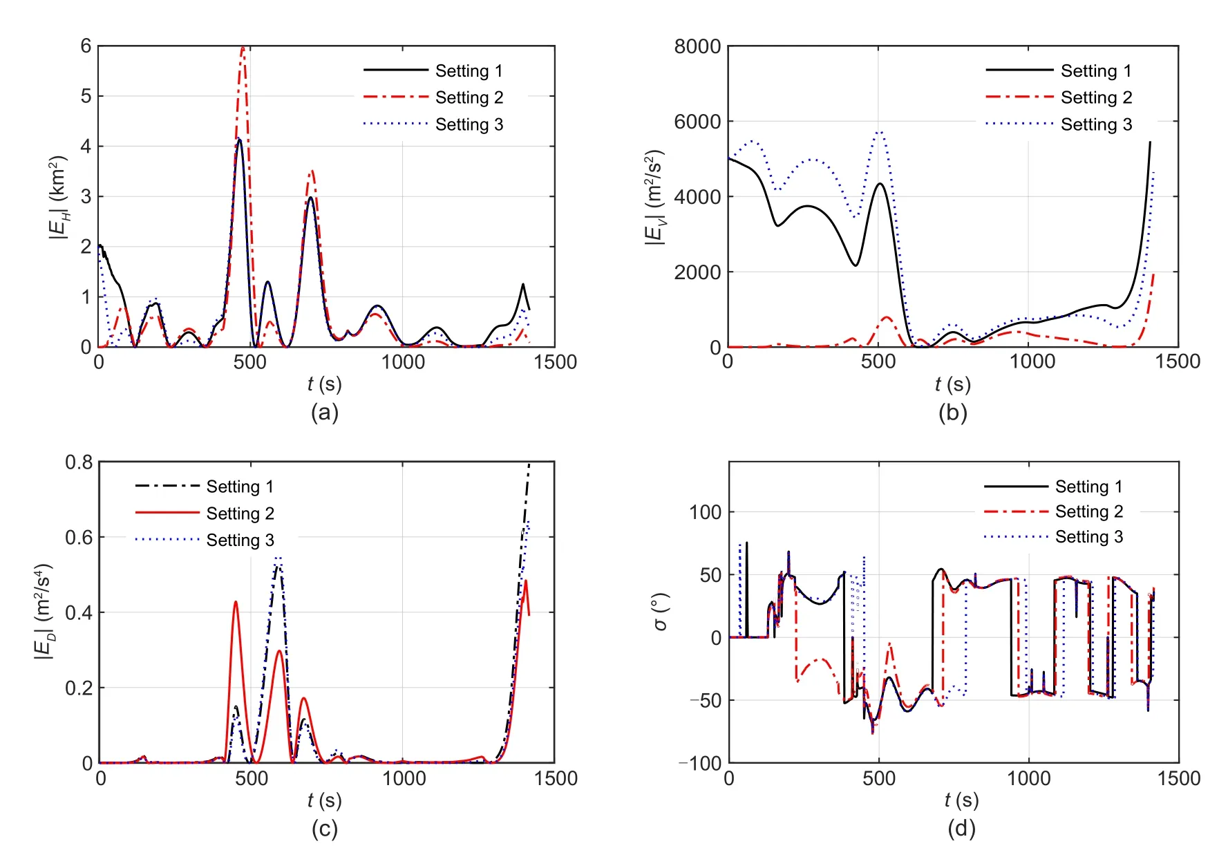
Fig.8 Simulation results with the influence of initial parameter measurement uncertainties:(a) altitude tracking error;(b)velocity tracking error;(c)drag tracking error;(d)bank angle profile
Acknowledgments
This work is supported by the National Natural Science Foundation of China(No.11972368)and the Natural Science Foundation of Hunan Province(No.2021JJ10045),China.
Author contributions
Kai AN designed the research and processed the corresponding data.Zhen-yun GUO wrote the first draft of the manuscript.Wei HUANG and Xiao-ping XU helped to organize the manuscript.Kai AN and Wei HUANG revised and edited the final version.
Conflict of interest
Kai AN,Zhen-yun GUO,Wei HUANG,and Xiao-ping XU declare that they have no conflict of interest.
