Particle captured by a field-modulating vortex through dielectrophoresis force
2022-03-12BingYan严兵BoChen陈波ZeruiPeng彭泽瑞andYongLiangXiong熊永亮
Bing Yan(严兵), Bo Chen(陈波), Zerui Peng(彭泽瑞), and Yong-Liang Xiong(熊永亮)
School of Aerospace Engineering,Huazhong University of Science and Technology,Wuhan 430074,China
Keywords: field-modulating vortex,dielectrophoresis,fluid-particle interactions
1. Introduction
Lab-on-a-chip (LOC) technology, and its advantages of portability and integration, have attracted a lot of attention.The LOC can integrate expensive and large-volume laboratory instruments on a tiny chip without sacrificing performance. It can implement a multifunction process by integrating many components,such as sample pretreatment,sample transportation,particles manipulation,the detection and analysis of onchip reactions and consequences,etc.[1]Particle manipulation is a key process that can affect detection accuracy. Dielectrophoresis (DEP) is commonly used for particle manipulation, and it has unique advantages in many respects, such as low cost,fast speed,high efficiency,high sensitivity,excellent controllability,etc.
In DEP, particles are suspended and subjected to a net force due to the polarization of an uneven electric field and the generation of relative motion. The electric field gradient is an important factor for DEP performance. Pure DEP technologies are divided into the microelectrode-based DEP(eDEP) and insulator-based DEP (iDEP). In the early stages,eDEP was widely used to manipulate particles in a microfluidic system because the system could utilize low voltages,small electrode volume, and electrodes of any shape.[2]According to the arrangements of microelectrodes embedded within microchannel,eDEPs are divided into planar electrodes(2D eDEP)(here,2D is an abbreviation for two-dimensional),multilayered electrodes (3D eDEP) (here, 3D is an abbreviation for three-dimensional), and microarray dot electrodes.[3]Thin-film 2D electrodes produced with a simple manufacturing process could meet the requirements of DEP and manipulate particles.[4-6]In a 3D eDEP system, the DEP force generated among the multilayered electrodes was used to manipulate target particles.[7-9,11]Standard photolithographic technologies were used to fabricate microarray dot electrodes,[3]which generate a DEP force that can be used to manipulate particles.[12]However, the eDEP has a narrow control range,so its efficiency is low. To address this, researchers have embedded insulating posts in channels to amplify the working region of the DEP. This approach is called iDEP, and is widely used to manipulate the particles and cells.[13-16]However,when high voltages are used in an iDEP system,temperature inside the device increases to a high level due to Joule heating. Since pure DEP technology has its own shortcoming, many researchers have also combined DEP with other microfluidic technologies to manipulate particles, such as the hybrid dielectrophoresis-inertial method,[17]combining DEP with deterministic lateral displacement,[18]combining DEP and electroosmotic micro-vortex,[19-22]and other approaches.These combined technologies can not only make full use of the advantages of pure DEP technology, but also avoid their shortcomings.
When particles move in the vortices,the influence of vortices on particles depends on the parameters of the particles,such as their sizes[23,24]and densities,[25]as well as the properties of the fluid. In the microfluidic technology, it has also been found that the orbit of a particle in a vortex is related to the size of that particle.[26,27]Small particles move in the outer orbits, while large ones travel along the inner orbits nearer to the vortex center.[28,29]Shenet al.[30,31]found that the orbit of a particle varies with size, density, and inlet Reynolds number, and observed that the area of the orbit of small particles is smaller than that of large particles. Haddadi and Di Carlo[32]studied the interaction between vortex flow and neutrally buoyant spherical particles in channels,and corroborated that the particles of a limited size spiral toward a unique limit cycle orbit. Further,this spiraling flow generates exchanges of fluid mass between the main flow and the vortex flow. Moreover,researchers also found that the motion of a particle differs from tracers that follow streamlines in practical applications,as the presence of a finite size particle can disturb the surrounding fluid flow.[33]However,there are few studies on the combined dielectrophoresis or field-modulating vortex manipulation of particles. In addition, most of the researches are only limited to the influence of the flow field on the particles,ignoring the influence of the particles on the flow field. In this paper,the fluid-particle interactions in a microfluidic system, where the efficient particle manipulation is realized by combining DEP and field-modulating vortex,are investigated numerically by a finite difference method (FDM) for electric field distribution and a lattice Boltzmann method (LBM) for the fluid flow. The influence of the density, diameter and initial position of the particle, and the velocity of the fluid flow on the dynamics of the system are studied systematically. The movement of particle and the capture of particle by vortex in the presence of nDEP force are compared with those in the absence of nDEP force,and the mechanism of field-modulating vortex and DEP combined to manipulate particles is analyzed.Furthermore, the flow field around the particle is analyzed to explore the underlying mechanism.The results obtained in the work may provide theoretical support for engineering applications of field-controlled vortices to manipulate particles.
2. Mathematical model
In this work, electroosmotic flow appears in a channel,full of electrolyte solution, after an external electric field has been applied along it. When a modulating electrode is embedded on the channel wall, slip velocity is used to disturb local flow field,and thus generating a vortex. Because the aspect ratio of the cross-section is large, the fluid flow in the channel can be approximately regarded as a 2D flow between parallel plates.[34,35]The 2D geometrical model is shown in Fig.1. The corresponding characteristic constants are input as follows: the width of the channelH=100 μm,and the length of the main channelLc=5H=500 μm. A modulating electrodeLe=1/10Lcis used to generate the modulating field.

Fig.1. Geometry of the 2D model.
2.1. Governing equation of electric fields
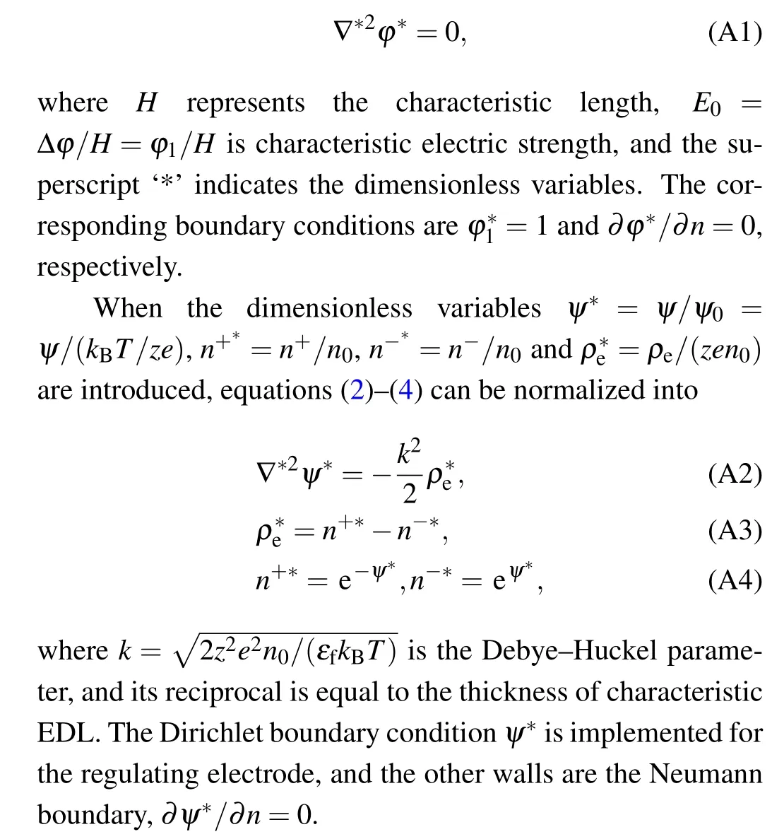
The electric field contains two parts: the driving electric field and modulating electric field. A driving electric field is generated when the electrodes are located on the inlet part and on the outer part,respectively as shown in Fig.1,and the electric potentials are appointed toφ1andφ0=0. The driving field is governed by the Laplace equation as follows:[36]

whereεfis the permittivity of the electrolyte.eandzare respectively the elementary charge and the valence of the ions(|z+|=|z-|=z)for the symmetric solution).n+andn-represent the concentrations of the positive and negative ions,respectively. Here,n0=CNadenotes the ion number concentration of the solution, whereCis the molar concentration of ions,and the Avogadro number isNa=6.022×10²³. In addition, the Boltzmann constant iskB=1.380×10⁻²³J/K. The corresponding boundary condition isψ=ψ1for the modulating electrodes, but for the remaining walls, the boundary conditions are∂ψ/∂n=0.
2.2. Governing equation of flow field
In this work,the fluid is considered as incompressible and viscous, and the continuity equation and the Navier-Stokes equation are expressed as
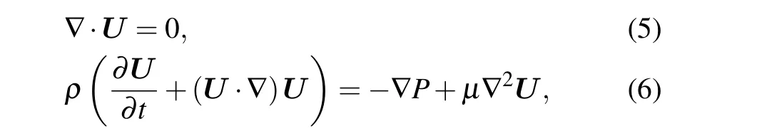
respectively, whereρandμdenote the density and viscosity of the fluid, respectively.Urepresents the velocity vector of the flow field,andPis pressure. The boundary conditions arep=0 for both the inlet and the outlet. For the channel wall,the slip velocityU=U0=-εEψ/μis applied to the modulating electrode,and for remaining walls,U0=0,whereEis the electric field strength.
2.3. Governing equation of particle motion
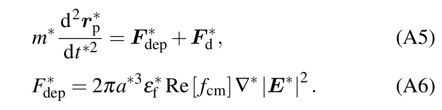
The particle motion obeys Newton’s second law,and it is subjected to DEP forceFdepand the hydrodynamic forceFd.Thus,the governing equation is given as follows:

whererdenotes the radius of this particle,and Re[fcm]represents taking the real part. In addition,fcm=(σp-σf)/(σp+2σf)is the Clausius-Mossotti factor for the direct current(DC)electric field, whereσfdenotes the conductivity of solution,andσpis the conductivity of the particle.The particle is spherical,solid and uniform,and the conductivity of the particle isσp=σp,bulk+2Ks/r, whereσp,bulkis the bulk conductivity,which is approximately zero for polystyrene dielectric particles, andKsis surface conductance, which is changed from 0.2 nS to 2.1 nS.[38]
When a solid particle moves,a momentum exchange occurs between this particle and the flow field. Thus, momentum exchange is used to calculate the hydrodynamic forceFd.The detailed process of the momentum exchange method is described in the next section.
3. Numerical method
In this work,the fluid-particle interactions in a microfluidic system are investigated numerically by an FDM for electric field distribution and an LBM for the fluid flow.A uniform mesh is used for the numerical solutions of the abovementioned equations,in which the solution domain is represented by s series of cells of sizeh.
3.1. Solution of electric field by FDM
To obtain the distribution of the electric field across microchannels, the finite difference method is used to solve the Laplace equation and the Poisson-Boltzmann equation. Thus,an over-relaxed iterative scheme is applied, and iterative solutions continue until their convergences. The corresponding equations are given as follows:
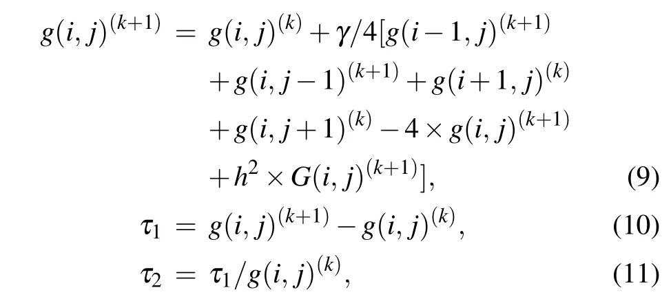
whereg(i,j)represents the electric voltageφ(i,j)orψ(i,j),kis the number of iterations,andγis the over-relaxation factor,which ranges from 0 to 2. Here,if the notationG(i,j)equals 0, equation (9) is used to solve the Laplace equation. When equation(9)is used to solve the Poisson-Boltzmann equation,the notationG(i,j) is equal to-ρe/ε. Theτ1andτ2are absolute error and relative error,respectively. When the absolute error and relative error are both small enough, the results are considered to be convergent.
3.2. Solution of flow field by LBM
The lattice Bhatnagar-Gross-Krook (LBGK) model is the most widely used in LBM,which can function with a single time step and does not require internal iterations. Thus,the lattice Boltzmann equation[39]is employed in the present simulation,i.e.,
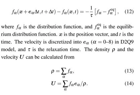
For a straight microchannel wall,bounce-back conditions are adopted.[40]After completing the stream steps,for the boundaryy= 0, the corresponding boundary conditions are implemented, includingf2=f4,f5=f7, andf6=f8. For the boundaryy=H, the slip velocityu=u0is applied to the modulating electrode, with the remainder of the boundary atf4=f2,f7=f5, andf8=f6. For a moving curved boundary,the treatment proposed by Lallemand and Luo[41]is adopted,namely,an extension based on the combined method of bounce-back and interpolations is used to treat the curved boundaries.[42]
3.3. Momentum exchange between particle and flow field
The method of momentum exchange is based on the bounce-back scheme. After the collision step is completed,the solid wall can obtain the momentum from the fluid node.At the same time,the fluid node can also obtain momentum by bouncing from the solid node.[39,43]Thus,along this direction,the hydrodynamic force on a solid boundary node at timetis given as
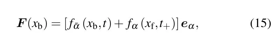
wheret+is the post collision time,xfis the position of the fluid node,andxbis the position of solid node. Therefore,the total hydrodynamic force on the particleFdis given by
4. Results and discussion
In this paper, an aqueous solution of potassium chloride at temperatureT= 293 K is taken as a working solution. The corresponding properties of the fluid are densityρ= 1000 kg/m3, viscosityμ= 10-3Pa·s, and permittivityεf=78ε0, whereε0=8.85×10⁻¹²F/m denotes vacuum permittivity.[38]A solid spherical particle is the goal particle.Grid independence is analyzed by studying the trajectories of a particle under different grid distributions as shown in Fig.2.Finally,a grid distribution of 1000×200 is selected. The simulation results are expressed in the dimensionless form. For the specific functioning of the dimensionless model,please refer to Appendix A.
4.1. Model validation
To validate the numerical results,the profiles of the electric field and the flow field obtained by different methods are compared. When a modulating electric field isψ1=-2, a cross section at the head of the modulating electrode is selected,and the distribution of the modulating electric field on this cross section is compared as shown in Fig.3. The results are similar to those calculated by COMSOL. When the slip velocity isu0=2×10⁻², the flow field is obtained by using different methods as shown in Fig.4. The forces on this particle, obtained by different methods, are validated, when this particle moves near to the modulating electrode. As shown in Fig.5,the changes of the forces with their locations are similar,but their magnitudes are different. This is because only the effects of the flow field on the particle are considered by using the COMSOL calculation,and the influence of this particle on the flow field is ignored. In the current method in which the FDM is combined with the LBM,the interaction between the particle and the flow field is considered. Moreover, the DEP force exerted on this particle in thexdirection is small, and can be neglected. In this work, the movement of this particle in theydirection is mainly studied.
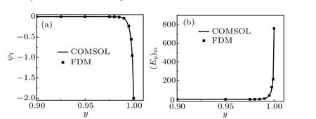
Fig.3. (a)Distribution of modulating electric voltage ψ1,and(b)distribution of modulating electric field intensity(Ey)m.

Fig. 4. Schematic diagram of flow field obtained with (a) COMSOL, and(b)LBM.
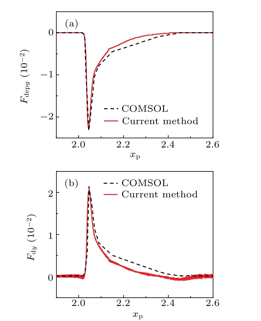
Fig.5.Variations of(a)DEP force Fdep,and(b)hydrodynamic force Fd with location xp.
4.2. Comparison between results with and without DEP force
When the slip velocity isu0= 2×10⁻², a flow field is produced as shown in Fig. 2(a). The vortex is generated around the modulating electrode due to the disturbance of local flow field.When a particle with a radius of 5 μm is released from the initial positionyp=0.5,it moves with the fluid within the channel.This particle is carried downstream of the channel when it is not subjected to a DEP force as shown in Fig.6(a).Since there is only a weakly repulsive effect,it can move closer to the wall as it decelerates as shown in Fig. 6(b). However,when a negative DEP (nDEP) force is exerted on this particle,it cannot approach to the modulating electrode due to the strong repulsive effects of the nDEP force, and is eventually pushed into the vortex. Its trajectory first drops sharply and then smooths out as this particle is pushed away from the modulating electrode by the nDEP force,because the net force on the particle varies with its position. Since the nDEP forceFdepis active and the hydrodynamic forceFdis passive,Fdvaries withFdep. According to Eq. (8),Fdepis related to the gradient of the square of strength of the electric field,which means thatFdepis related to the distance between this particle and the modulating electrode. A particle moves near the modulating electrode and as this particle approaches to the modulating electrode,Fdepyis enhanced as shown in Fig.7(a). When it is away from the modulating electrode,Fdepydecreases. Meanwhile,Fdyalso changes in a similar way toFdepyas shown in Fig.7(b),but their functions are opposite. Since the net forceFyis equal to the sum ofFdepyandFdy,its variation can reflect strength between the two forces. As seen in Fig.7(c). WhenFdepyexceedsFdy,Fyis negative.On the contrary,Fyis positive asFdepyis less thanFdy. When theFyis equal to 0, it moves with the fluid flow.
As a particle moves with the fluid, an interaction occurs between the particle and the flow field. As a hydrodynamic force on this particle is obtained through momentum transfer with the flow field,the flow field is also subjected to the same magnitude and opposite force. To study this effect, a streamline that is formed at the same location of the channel inlet is selected as shown in Fig.8,and the variation in the streamline is used to describe the effect. Since the hydrodynamic force varies with the position of the particle,the effects of the particle on the flow field change with its position. As it moves near the head of the modulating electrode(xp≈2.07),as figure 9(b)shows, the variation in the flow field is significant because the hydrodynamic force is greater (Fdy ≈2.1×10⁻²). As it moves to the center of the modulating electrode (xp≈2.27),as illustrated in Fig. 9(c), the hydrodynamic force decreases(Fdy ≈0.2×10⁻²), so the variation in the flow field is weak.As it continues to move downstream (xp≈2.4), as shown in Fig.9(d), there is little variation in the flow field because the force decreases toFdy ≈0. Accordingly, the hydrodynamic force on a particle is stronger, which means that the interaction between this particle and the flow field is stronger, and the influence of the particle on the flow field is more significant.
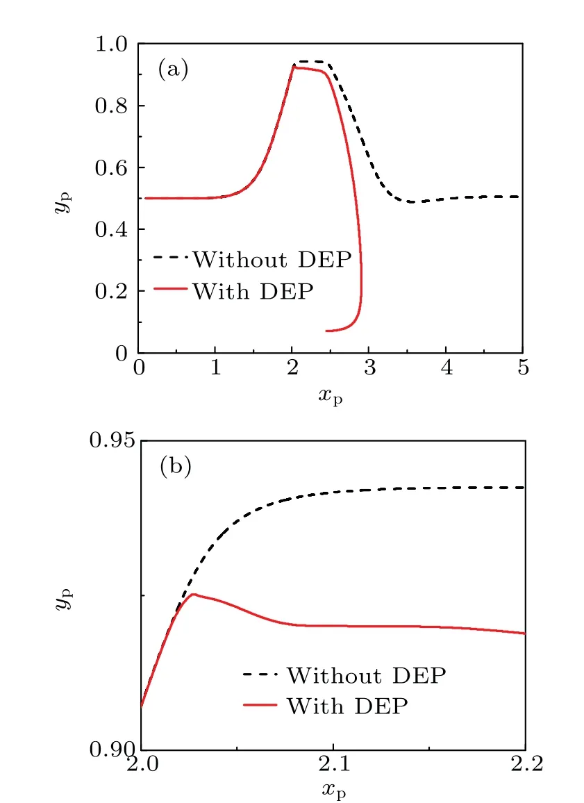
Fig.6. Schematic diagram of(a)trajectories in different conditions as particle moves within channel, and (b) local trajectories when particle moves near the head of modulating electrode.

Fig. 7. Variation of (a) DEP force Fdepy, (b) hydrodynamic force Fdy, and (c) net force Fy on particle with its position as it moves near to modulating electrode.

Fig.8. Schematic diagram of flow field as the particle moves within channel,showing(a)variation of streamlines at the same location, with particle at different positions. and variation of streamline,with this particle at xp ≈2.07(b),2.27(c),and 2.4(d).

Fig. 9. Schematic diagram of flow field in different conditions for (a) no particle moving with fluid flow, and particle moving to xp ≈2.07(b), 2.27(c),and 2.4(d).
4.3. Effect of initial position of particle
When the slip velocity isu0=2×10⁻²,a particle with a radius of 5 μm is released from a different initial positionyp.Its motion varies with theypwhen it moves with the fluid. As shown in Fig. 10(a), when the particle is not subjected to an nDEP force,it is released from the initial positionyp=0.125.As it moves near to the modulating electrode,it is closer to the vortex and carried into the vortex.As theqyincreases,this particle is closer to the wall and away from the vortex, finally,it is carried downstream of the channel. When an nDEP force is exerted on this particle,it is also captured by the vortex when its initial position isyp=0.125 as indicated in Fig.10(b).

Fig.10. A particle is released from different initial positions yp0,(a)its trajectories within channel when it is not subjected to an nDEP force,and(b)its trajectories under action of an nDEP force.
Moreover, as it is released from theyp= 0.5 and 0.8,the particle is pushed into the vortex by a strong nDEP force.Since it moves closer to the modulating electrode asypincreases, the distance between the particle and the modulating electrode is shorter. The maximum value of its location in theydirection (yp)maxincreases withypincreasing as shown in Fig.11(a).Therefore,the maximum absolute value of the DEP force|(Fdepy)|maxon this particle is enhanced asypincreases as seen in Fig.11(b),and the maximum absolute value of the hydrodynamic force|(Fdy)|maxand the net force|(Fy)|maxon this particle are also enhanced. Accordingly, the particle is more likely to be trapped by the vortex as it is released from a higheryp. Further,when this particle is subjected to the nDEP force,it is captured more easily by the vortex asyp0≥0.4.
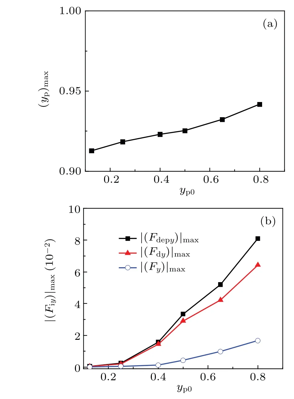
Fig.11. Variations of(a)maximum position(yp)max and(b)maximum absolute value of forces|(Fiy)|max exerted on particle with the initial position yp0.

Fig. 12. Schematic diagram of the interaction between a particle and the flow field at initial positions yp0=0.25(a),0.5(b),and 0.8(c).
Figure 12 displays the effects of a particle on the flow field,when the strongest hydrodynamic force is exerted on this particle. When the particle is released from theyp=0.25,the interference is weak, as Fig. 15(a) shows. Since a stronger hydrodynamic force is obtained when this particle is released from a higheryp, the interference is more significant. As shown in Fig. 15(c), as the initial position increases toyp=0.8,the influence becomes more significant,and the flow field around the particle becomes obviously distorted.
4.4. Effect of particle density
For similar particle volumes,particle mass varies with its densityρp. In this subsection,a particle with a radius of 5 μm is released at the initial position(yp0=0.5). When it moves in the flow field(u0=2×10⁻²), its motion varies with its density. As shown in Fig. 13(a), when it is not subjected to an nDEP force, its density is respectivelyρp=0.2, 1, or 5, and is carried downstream of the channel. Since its velocity decreases more slowly for the particle with higher density, the particle with a higher density approaches to the modulating electrode,and it is closer to the channel wall. When an nDEP force is exerted on the particle,it continues to be carried downstream of the channel when its density isρp=0.2 as seen in Fig.13(b).
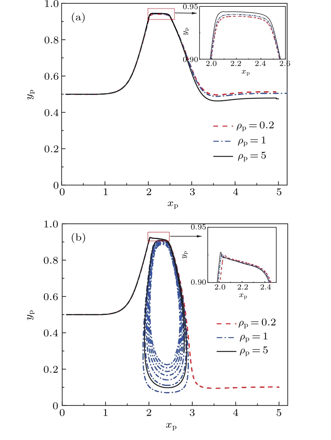
Fig.13. Trajectories of particle with different densities ρp moving with the fluid,for particle subjected to(a)nDEP force and(b)no nDEP force.
However, as its density increases to 1 or 5, the particle is pushed into the vortex by a greater nDEP force,and moves spirally and toward the center of the vortex. Since the particle has a higher density and can move closer to the modulating electrode,a stronger nDEP force is exerted on this particle as the distance between this particle and the modulating electrode shortens as shown in Fig.14. In a word,a particle with a higher density is subjected to a stronger nDEP force,so this denser particle can be captured by the vortex more easily.

Fig.14. Variation of nDEP force Fdepy on particle with density ρp when the particle is closest to the modulating electrode.
4.5. Effect of particle size
When particles of different sizes are released from the initial position (yp0= 0.5), they move in the flow field (u0=2×10⁻²). As shown in Fig. 15(a), when the particle is not subjected to an nDEP force, it is carried downstream of the channel. However,when an nDEP force is exerted on this particle,small particle is still carried downstream of the channel,but large particle is captured by the vortex. For example, a particle is carried downstream of the channel when its radius isr=2.5 μm, as illustrated in Fig. 15(b). As its radius increases to 5 μm or 10 μm, it is pushed into the vortex by an nDEP force, and moves spirally and toward the center of the vortex. It is pushed closer to the center of the vortex when the radius isr=10 μm. According to Eq.(8),the strength of the DEP force is related to the particle radius, and the nDEP force on the particle becomes stronger as its radius increases as shown in Fig.16. Thus,large particle is likely to be captured by the vortex.
It follows that a greater hydrodynamic force is generated for a larger particle due to a stronger nDEP force. For the interaction between the particle and the flow field,the influence of a larger particle on the flow field is more significant. When the radius isr=2.5 μm, the change in the flow field is not so large as observed in Fig.17(a),because the hydrodynamic force is weak. As its radius isr=10 μm, it is subjected to a stronger hydrodynamic force,so the surrounding flow field is significantly distorted as illustrated in Fig.17(c).

Fig. 15. Schematic diagram of the trajectories of particles with different radii,indicating its trajectories within the channel when(a)subjected to no nDEP force and(b)under action of nDEP force.
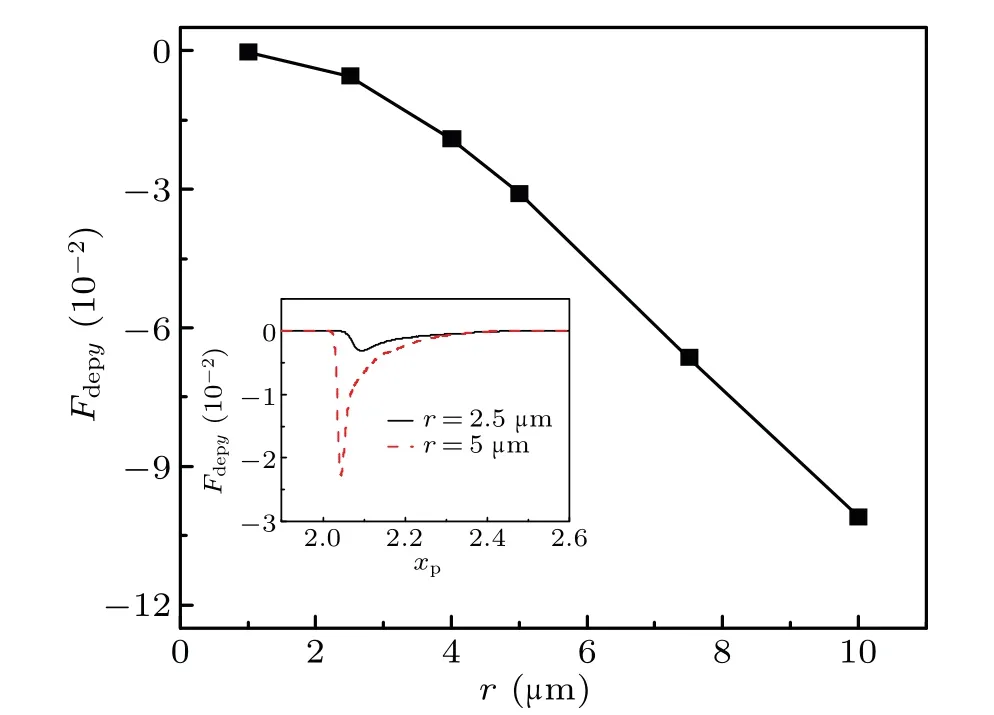
Fig. 16. Variation of nDEP force Fdepy on particle with particle radius r when moving closest to modulating electrode.
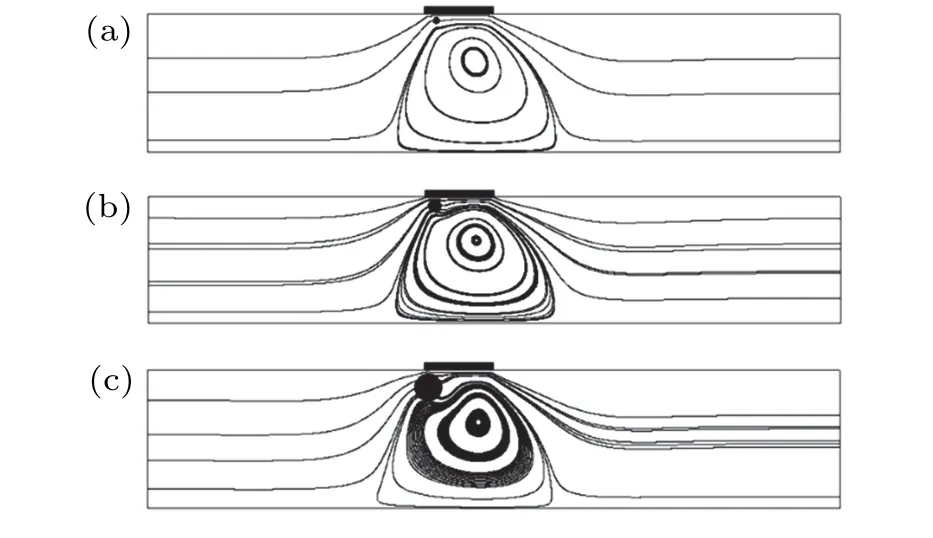
Fig. 17. Schematic diagram of influence of particles of different sizes ((a)r=2.5 μm,(b)r=5 μm,and(c)r=10 μm)on flow field when particles are the closest to the modulating electrode.
4.6. Effect of slip velocity
A particle with a radius of 5 μm is released from the initial positionyp0=0.5, and moves with the fluid. When an nDEP force acts on this particle, its motion varies with the slip velocityu0. As shown in Fig.18(a), when the particle is not subjected to an nDEP force, it is carried downstream of the channel. When it is subjected to an nDEP force, it can be captured by the vortex when the slip velocity falls belowu0=2×10⁻²as shown in Fig.18(b).
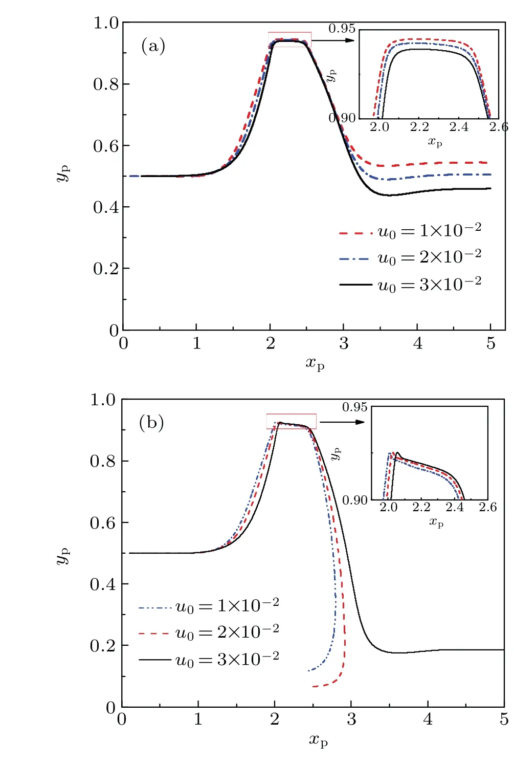
Fig.18. Trajectories of a particle when moving in a flow field with different values of slip velocities u0 (a)without and(b)with nDEP force acting on it.
As the slip velocity is higher thanu0=3×10⁻²,it is carried downstream along the channel. Moreover,as the particle moves close to the modulating electrode,its position in thexdirectionxpbecomes closer to the ending of the modulating electrode as theu0increases. However,the value of(yp)maxis approximate. Thus,the nDEP force on this particle is also approximate.Since this particle can pass through the modulating area faster at a greateru0,the time in which the DEP force acts on this particletEis shorter as observed in Fig.19(b). Accordingly, the particle is more likely to be carried downstream in a high-velocity flow field because it cannot be pushed into the vortex by the nDEP force within the short timetE. The results show that the ability of the vortex to trap this particle decreases in a high-velocity flow field,which is consistent with the finding of our previous work.[22,38,44]
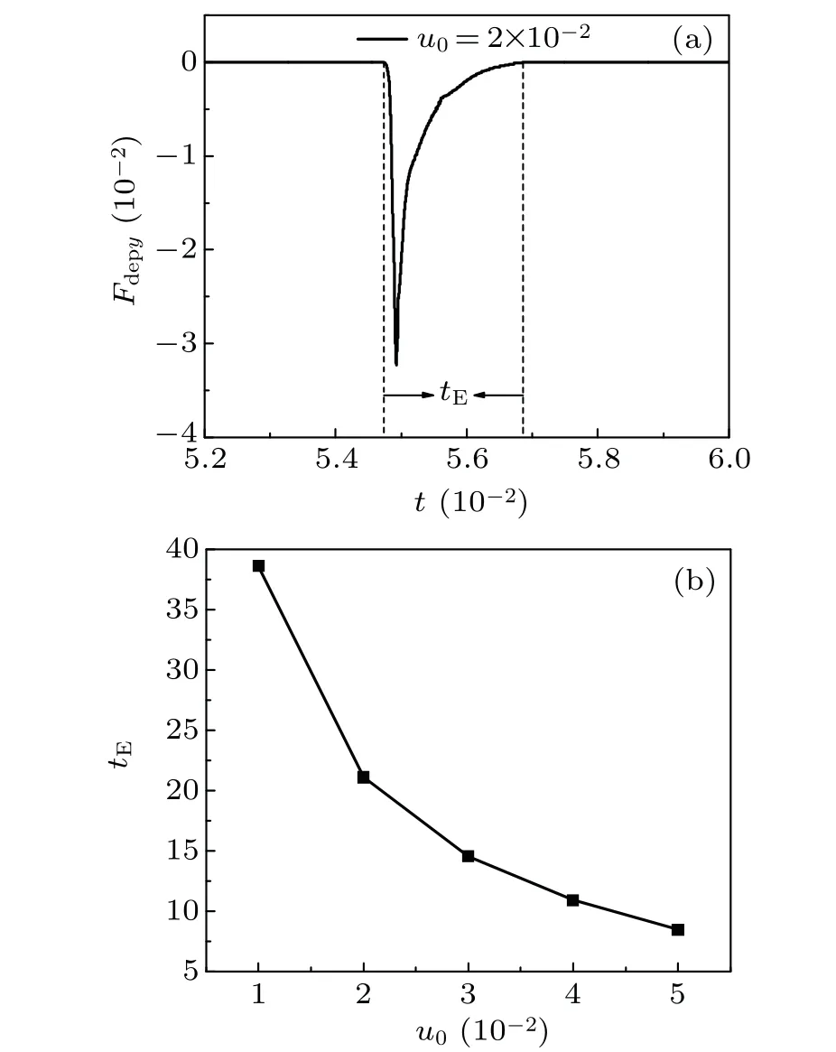
Fig. 19. (a) Variation of nDEP force on particle Fdepy with time t, and (b)variation of tE with u0.
5. Conclusions
In this work,an approach that combines the finite difference method and the lattice Boltzmann method is used to study the interactions between the particle and the flow field in a system that combines the field-modulating vortex and DEP. The particle moves with the fluid within the channel due to the hydrodynamic force.The particle without the nDEP force can be captured by the vortex when the particle is initially placed near the wall due to fluid-particle interactions. However,as theyp0increases, the particle cannot be captured by the vortex and moves downstream in the channel. It is found that when subjected to an nDEP force, the particle may be captured by the vortex over a wider range of parameters.The ability of the vortex to capture particle increases with the nDEP force increasing. Since the particle moves closer to the modulating electrode as theyp0increases, it is more likely to be pushed into the vortex by a stronger nDEP force. Moreover,the ability of the vortex to capture the particle increases with the density of the particle increasing because of a stronger nDEP force acting on the particle as it moves closer to the modulating electrode.Similarly,the particle is more likely to be captured by the vortex when theu0is lower orris larger. Therefore,in practical applications, theyp0is higher and theu0is lower, the vortex to capture particle is more favorable. In order to make sure a great efficiency of the system for manipulation of particle,theyp0andu0areyp0≈0.5Handu0=2×10⁻²,respectively.The effect of the particle motion on the flow field varies with its position. As a particle moves closer to the channel wall,its effect on the surrounding flow field becomes more significant.In addition,the influence of the particle on the flow field is enhanced with the increase of the size,density,or initial position in theydirection of particle.
Acknowledgement
Project supported by the National Natural Science Foundation of China (Granmt Nos. 11572139, 11872187, and 12072125).
Appendix A: Nondimensionalization of governing equation
A1. Nondimensionalization of governing equation of electric field
By introducingx*=x/H,y*=y/H,φ*= Δφ/E0H,equation(1)can be normalized as
A2. Nondimensionalization of governing equation of particle motion
By introducing the dimensionless variablesm*=m/m0,F*=F/F0, andγ= 6πaE0/ψ0, the characteristic force isF0=εfφ20. Thus equations(7)and(8)can be normalized into
猜你喜欢
杂志排行

Chinese Physics B的其它文章
- Surface modulation of halide perovskite films for efficient and stable solar cells
- Graphene-based heterojunction for enhanced photodetectors
- Lithium ion batteries cathode material: V2O5
- A review on 3d transition metal dilute magnetic REIn3 intermetallic compounds
- Charge transfer modification of inverted planar perovskite solar cells by NiOx/Sr:NiOx bilayer hole transport layer
- A low-cost invasive microwave ablation antenna with a directional heating pattern