Effect of Joule heating on the electroosmotic microvortex and dielectrophoretic particle separation controlled by local electric field*
2021-11-23BingYan严兵BoChen陈波YongliangXiong熊永亮andZeruiPeng彭泽瑞
Bing Yan(严兵), Bo Chen(陈波), Yongliang Xiong(熊永亮), and Zerui Peng(彭泽瑞)
School of Aerospace Engineering,Huazhong University of Science and Technology,Wuhan 430074,China
Keywords: dielectrophoresis,microvortices,Joule heating effect,particle separation
1. Introduction
Microfluidic technologies have become a powerful tool in a broad range of fields because of being small,portable,inexpensive,and easy to be used.In many applications,it is crucial to separate particles. Currently,the methods of separating particles are divided into passive and active methods according to the working principle. The passive methods mostly rely on geometry and design of the microchannel which separate the particles on the basis of shape,size,and deformability,[1]such as inertial displacement,[2]deterministic lateral displacement(DLD),[3]and others.[4,5]The active ways that employ external fields to achieve separation include the centrifugation,[6]magnetic,[7]acoustic,[8]and so on. DEP is one of the most effective techniques to separate particles in microfluidic chips due to its controllable, label-free, and accurate manipulation of targeted particles.[9-11]
The term DEP was first coined by Phol[12]in 1951. DEP refers to the movement of polarized particles relative to the electrolyte solution in an uneven electric field. Traditionally,arrays of microelectrodes are embedded into the microchannel walls to build the non-uniform electric field.[13-15]Electrodes of various materials,such as AgPDMS,[16]liquid metal electrodes,[17]and others,with different configurations and dimensions were integrated into microchannels to ensure the effective DEP regions. Composites of sliver (Ag) and PDMS were used for the first time to construct microelectrodes to create a non-uniform electric field by Nieet al.[18]They employed the device to attain the continuous separation of 2-µm and 15-µm beads. Zhanget al.[19]achieved the separation of live and dead HeLa cells with high efficiency with a three-dimensional (3D) electrode integrated within silver-PMDS composites. Recently,researchers also used electrodes of other materials to separate particles. For instance, Hajariet al.[11]designed a DEP-based device with an oblique gold electrode. Particles with different sizes were able to be separated in operation and with no on/off electric field by employing their design. Moreover, liquid electrodes have also been increasingly studied by researchers. Sunet al.[20]separated MDA-MB-231 human breast cancer cells from human adipose-derived stem cells with high purity by applying liquid electrodes. With the progress of production technology,some researchers attained particle separation with composite of electrodes-based DEP and irregular obstacles.[21-24]Yasukawaet al.[25]utilized an slanted electrodes to build the uneven electric field, and achieved the continuous separation of white and red blood cells based on negative dielectrophoresis(nDEP).Meanwhile,the low voltage was generally used to generate a non-uninform electric field within electrodes-based DEP,so the Joule heating effect was neglected.
Joule heating is a ubiquitous phenomenon of resistive heat generation in electric field-driven fluid flows.[26,27]The Joule heating effect results in a temperature gradient in the channel. This gradient consequently affects the properties of the temperature-dependent electrolyte. Moreover, the electrokinetic mechanisms and associated processes including biomedical and biochemical reactions are also influenced.[28-31]Xuanet al.[32-35]have done considerable work on the effect of Joule heating in microfluidics. They studied the effect of Joule heating on electroosmotic flow in theory, through experiments and numerical simulations, and demonstrated that the Joule heating effects could disturb electroosmotic velocity profiles. Yanet al.[36]demonstrated that the Joule heating effect increased with an increasing of voltage, and the temperature in the microchannel increased. In addition,other researchers have also studied the Joule heating effect in electroosmotic flow.[37,38]Joule heating is easily appears in insulator-based DEP when high voltage is applied.Xuanet al.[39-41]showed that Joule heating could weaken DEP focusing and trapping in insulator-based DEP microfluidics by experimental and numerical studies. The influence of the Joule heating effect on the manipulation of particles by the DEP force was studied by Hawkingset al.[42]Aghilinejadet al.[43]made use of mathematical modeling to study the effect of Joule heating with iDEP, and proposed a separation scenario for the selective trapping of circulating tumor cells.They considered that the high electric field resulted in high temperature gradients in iDEP, so that the Classius-Mossoti factor was also altered due to the conductivity varying with temperature. Furthermore, they also confirmed that the Joule heating effect could enhance the positive DEP to trap cells.Gallo-Villanuevaet al.[44]studied the temperature increase inside iDEP devices with seven distinct channel designs of different post array characteristics. They found that the effect of the insulators made a difference in the temperature increase of approximately 4°C during the design studies.
Our team proposed a method for particle manipulation by combing DEP and field-modulated electroosmotic vortex.This method achieved the separation of particles with different diameters at a low voltage.[45]Results demonstrated that the separating efficiency could be improved by increasing the electric field. However, the Joule heating effect should be taken into account when applying a high voltage, especially for the high conductivity of the solution. The objective of this paper is to study the effects of Joule heating on the particle trapping capability of micro-vortex. The coupled equations which include the electric field, flow field and temperature field are numerically solved by COMSOL Multiphysics. In addition, the effects of the driving voltage, modulating voltage, conductivity of the solution, convective heat transfer coefficient of channel wall, electrode length, and channel width on the Joule heating along with the separation rate of small particles are analyzed in detail, which provides a theoretical reference for the application of continuous particle separation.
2. Mathematical model
In practical applications, the fluid flow in channel can be approximately regarded as a two-dimensional (2D) flow between parallel plates[46,47]since the ratios of the crosssectional aspect are large. In this paper, electroosmotic flow(EOF)appears in the channel after applying an external electric field along the channel, which is full of electrolyte solution. As the modulating electrodes are vertically embedded on the channel wall, the vortices are generated due to the local interference of the modulating field.[40,42]The 2D geometrical model is show in Fig.1. The corresponding characteristic constants are input as follows:the width of the channel isH=100µm,the length of the main channel isLc=7H=700µm,the length of the reservoir isLr=3H=300µm,and the width of the reservoir isHr=4H=400µm. A pairs of symmetrical modulating electrodes (Le=15 µm) are used to generate the modulating field.

Fig.1. Geometry of the 2D model.
2.1. Governing equations of the EOF
The electrodes are located in reservoirs to create the difference of voltage and the external electric field, as shown in Fig. 1. The voltages of the two electrodes are appointed toϕ1and 0, respectively. When the substrates are considered as non-conducting substrates,the applied electric field is governed by the following equation:[34,48]

whereσf(T)is the temperature-dependent conductivity of solution,σf0is the conductivity of the solution at room temperatureT0=293 K, andTis the temperature within the solution. The corresponding boundary conditions areϕ=ϕ1and∂ϕ/∂n=0,respectively.
The induced electric fieldψin the field-modulated EDL is related to the net charge densityρeby the Poisson equation as follows:[27,49]

whereεf(T) is the temperature-dependent permittivity of the electrolyte, andεf0is the permittivity of the solution at room temperatureT0= 293 K. The net charge densityρeis proportional to the concentration difference between symmetric cations and anions,which is given by[27]
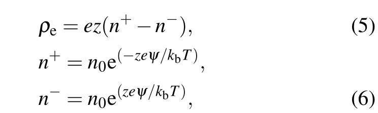
whereeandzare the elementary charge and the valence of ions (|z+|=|z−|=zfor a symmetric solution) respectively.n+andn−represent the concentrations of the positive and negative ions, respectively. Furthermore,n0=CNAdenotes the ion number concentration of the solution, whereCis the molar concentration of ions, and Avogadro’s number isNA=6.022×10²³. In addition, the Boltzmann constant iskB=1.380×10⁻²³J/K. The corresponding boundary conditions areψ=ψ1for the modulating electrodes, but for the remaining walls,the boundary conditions are∂ψ/∂n=0.
In this study, the fluid inertia is ignorable due to the vanishing Reynolds number of the fluid flow. Regarding an incompressible viscous fluid, the continuity equation and Navier-Stokes equation are as follows:[50]

hereVandpare the velocity vector of the fluid flow and the pressure, respectively.ρis the density of fluid, andηf(T) is the temperature-dependent fluid viscosity.ρeEis the electric force exerted on the fluid,in which the electric field intensityEconsists of the driving and modulating fields. The governing equation is as follows:

The boundary conditions arep=0 for the inlet and outlet. For those channel walls,the boundary conditions areV=0.
2.2. Governing equations of temperature field
The steady temperature field with the induced Joule heating effect in the solution is governed by the following energy equation:[34,48]

wherecpis the specific heat of the solution, andkf(T) is the temperature-dependent thermal conductivity of the solution.The last term of the right side in Eq.(11),i.e.,σf(T)(E·E),is the generating rate of local Joule heating as heat source.The corresponding boundary conditions are specified asT=T0for the inlet and outlet, and the rest of the channel wall is bounded by convection−n·(k∇T)=h·(T1−T0), whereh=300 W/(m2·K) is the convective heat transfer coefficient andT1is the ambient temperature.[48]
2.3. The governing equations of particle motion
The motion of the particles is governed by Newton’s second law of motion, and the particles are only affected by the hydrodynamic forceFdand DEP forceFdep. They are represented respectively by[45]

whereais the radius of particle,andVpis the velocity of particle.fcmis the Clausius-Mossotti factor,and it can be calculated in direct current(DC)electric field[45]
whereσpis the particles conductivity. For a solid homogeneous spherical particle, the conductivity can be written as[51,52]

whereσp,bulkis the bulk conductivity of the particle,which is almost zero for polystyrene dielectric particles.Ksis the surface conductance,and its value ranges from 0.2 nS to 2.1 nS.
3. Results and discussion
3.1. Model validation
The numerical model is validated in DC and alternating current (AC) electric fields, respectively. The numerical results are compared with the experiment results of Yanet al.[35]at different DC applied voltages.And the numerical results are compared with those of Sridharanet al.[34]at different pure AC applied voltages. The results of the temperature increases within the channel due to the Joule heating effect are shown in Figs. 2 and 3. The slight difference between the two profiles could be the reason that the practical system measurement was occurred in 3D case but the numerical results were obtained in 2D case.

Fig. 2. Comparison of the distribution of temperature along the channel centerline obtained by Yan et al.(point)and our numerical results(line).The results are at 25 V and 50 V with DC electric field from bottom to top,respectively.

Fig. 3. Comparison of the distribution of temperature along the channel centerline obtained by Sridharan (point) and our numerical results(line).The results are at 400 V, 600 V, and 800 V from bottom to top,respectively.
3.2. Joule heating effect in the microchannel
A potassium chloride (KCl) aqueous solution is used as the working solution at an ambient temperature ofT0=293 K.[45]At ambient temperature, the electrolyte permittivity isεf0= 80ε0, whereε0= 8.85×10⁻¹²F/m denotes the vacuum permittivity. The density of the electrolyte isρ=1000 kg/m3, and the viscosity of the electrolyte isηf0=0.001 Pa·s. The conductivity and the thermal conductivity of the electrolyte areσf0= 0.1 S/m andkf0= 0.61 W/(m·K),respectively. In this work, gravity is neglected, as the particle density is considered to be equal to the density of the solution. The separation of differently sized particles can be achieved. The same Clausius-Mossotti factors are designated asfcm=−0.5,so that all particles are nDEP particles. When the particles move towards the modulating electrodes with fluid flow, they are pushed away from the modulating electrodes due to the nDEP force.
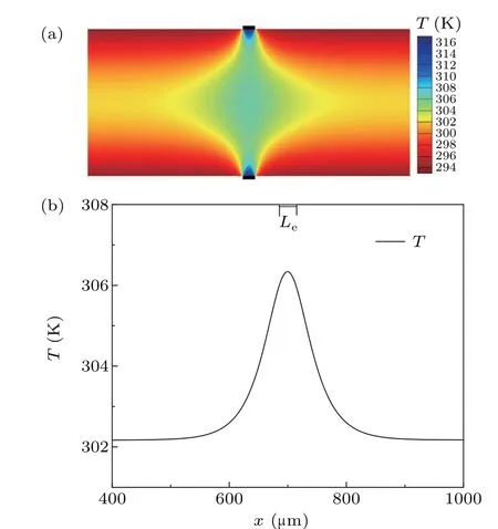
Fig.4. Distribution of temperature when the applied voltage and the conductivity of solution is designed (ϕ1 =70 V, ψ1 =−0.425 V, σf0 =0.1 S/m).(a)Profile of the temperature around the modulating electrodes;(b)the temperature distribution along the centerline of the channel.The rectangular strip represents the location of modulating electrode.

Fig.5. Variation in the maximum temperature Tmax with an applied voltage.(a) Variation in the maximum temperature Tmax with the driving voltage ϕ1 when the modulating voltage is −0.2 V,−0.425 V,and −0.5 V respectively;(b)variation of the maximum temperature Tmax with the modulating voltage ψ1 when the driving voltage is constant.
It is common that the Joule heating effect caused by the local electric field leads to uneven temperature distribution in the channel. The Joule heating effect is more significant when the applied voltage and conductivity of the solution are high.As shown in Fig.4(a), the non-uniform temperature distribution in the channel is caused by the Joule heating effect, and the temperature around the modulating electrode is higher than anywhere else, as shown in Fig. 4(b). The reason is that the local electric field intensity around the modulating electrodes achieves the maximum value, thus the Joule heating effect is the strongest around the modulating electrode according to the Eq.(11). The maximum temperatureTmax,which is measured at the midpoint of the modulating electrodes,increases with an increasing voltage. The variation in the temperature is more sensitive to the modulating voltage. For example, when the modulating voltage isψ1=−0.2 V, the variation in the temperature is mild with the increasing driving voltage,as shown in Fig.5(a). However, the temperature clearly increases with an promoting modulating voltage for a constant driving voltageϕ1=70 V, as figure 5(b) shows. The difference can be attributed to the local electric field,which is mainly influenced by the modulating voltage.
3.3. Definition of the separation rate
To study the particle separation,a group of large particles witha1=10 µm and small particles witha1=5 µm are released in the upstream channel, as shown in Fig. 6(a). These particles are initially driven by the hydrodynamic force and move downstream of the channel as the fluid flows.When they are near the modulating electrodes,a strong nDEP force exerts on the particles due to the existence of the local uneven fields.The particles are pushed away from the modulating electrodes,and move to the vortices in the center of the channel. Furthermore,according to Eq.(14),a stronger negative DEP force is exerted on the large particles at the same condition, so these large particles are more likely to be captured by the vortices.The separation rate of the small particlesζL, which denotes the ratio of the number of small particles trapped downstream of the channel to the total number of small particles released upstream,is a measure of the separation efficiency. The separation rate isζL=0,when all the small particles are also captured by the vortex or the large particles are also transported downstream, as shown in Figs. 6(b) and 6(e). When small particles are partially carried downstream and the large particles are all captured by the vortices,the corresponding separation rate is 0<ζL<100%, as shown in Fig. 6(c). As these large particles are wholly captured by the vortices, and the small particles are totally transported downstream, the separation rate isζL=100%,as shown in Fig.6(d).
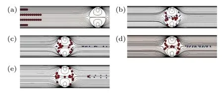
Fig. 6. Schematic diagram of the motions of two types of differently sized particles released upstream of the microchannel and the separation rate of small particles. (a) Initial release of the particles, (b) ζL =0, (c) 0<ζL <100%,(d)ζL =100%,and(e)ζL =0. The red points denote particles with a1=10µm,the blue points represent particles with a2=5µm.
3.4. Comparison of various driving voltages without and with the Joule heating effect
In this subsection, the driving voltage is adjusted when the other conditions remain unchanged. The result shows that the channel fluxQincreases with an increasing driving voltage,as shown in Fig.7. The result is attributed to the increasing axial electric forceρeExwith an increasing driving voltage. The hydrodynamic forceFdis proportional to the flow velocity. According to Eq.(13),the axial hydrodynamic forceFdxis proportional to the driving voltage. When the driving voltage is low, the small particles are completely trapped by the vortices as the hydrodynamic force is not able to carry the small particles out the vortices. The axial hydrodynamic force is enhanced by augmenting the driving voltage, so the small particles are partially or totally carried downstream. It is noticeable that the large particles can be carried downstream as the driving voltage is high enough. All the above observations are in agreement with Xie’s work.[45]

Fig. 7. Variation in the channel flux Q and the separation rate ζL with the driving voltage ϕ1 for the modulating voltage of ψ1 =−0.425 V.The solid rectangles denote those without the Joule heating effect,and the hollow circles represent the cases with the Joule heating effect. The number of points along the dotted line indicates the separation rate ζL with the Joule heating effect,and the number of points along the solid line indicates the separation rate ζL with the Joule heating effect.
When the Joule heating effect is considered,the viscosity of electrolyteη(T) decreases with increasing temperature as shown in Eq. (9), so the flow velocity and the channel fluxQincrease, as shown in Fig. 7. Thus, when the Joule heating effect is considered, the particles can move closer to the modulating electrodes along the flow than without Joule heating, as illustrated in Fig. 8. When the particles are closer to the modulating electrodes, a more negative DEP force acts on them. Accordingly, the particles tend to be captured by the vortices. For instance, in the case without the Joule heating effect, the separation rate isζL=100%when the driving voltage is 70 V,as shown in Fig.9(a),and the channel flux isQ=7.6826×10⁻⁹m3/s. However, the same separation rate is attained at a higher driving voltage ofϕ1=120 V when the Joule heating effect is considered, as figure 9(d) shows, and the channel flux isQ=1.128×10⁻⁸m3/s.It is noticeable that the separation efficiency is better because perfect separation is achieved with a larger channel flux,when the Joule heating effect is considered.

Fig.8. Motion trail of a small particle is shown when the applied voltage and other conditions remain constant(ϕ1=70 V,ψ1=−0.425 V,σf0=0.1 S/m),(a) motion trail of a small particle and (b) motion trail of a small particle around the modulating electrode. qx is the position of a small particle in the axial direction, and qy is the position of a small particle in the vertical direction.
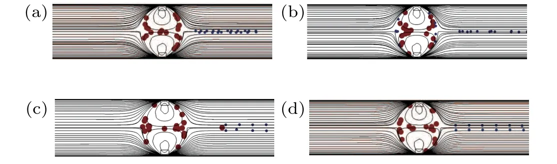
Fig. 9. Schematic diagram of showing particle motion with different driving voltages ϕ1 for a constant modulating electric field (ψ1 =−0.425 V)and other conditions, (a) ϕ1 = 70 V without the Joule heating effect, (b)ϕ1 =70 V with the Joule heating effect, (c) ϕ1 =120 V without the Joule heating effect,and(d)ϕ1=120 V with the Joule heating effect.
3.5. Comparison of various modulating voltages without and with the Joule heating effect
In this subsection,the modulating voltageψ1is changed from−0.4 V to−0.5 V while the other conditions remain unchanged. The result shows that the channel fluxQincreases with an increasing modulating voltage, as shown in Fig. 10.This result can be attributed to the stronger electric force because of the increasing modulating voltage. Both the DEP forceFdepand hydrodynamic forceFdincrease with the increase in modulating voltage, so the variation of separation rateζLis complex. When the Joule heating effect is considered,the channel fluxQis greater than in the cases without the Joule heating. Therefore,the increase in channel flux is more significant with a stronger Joule heating effect. Moreover,the ability of the vortex to trap the particles is also improved with an increasing DEP force.
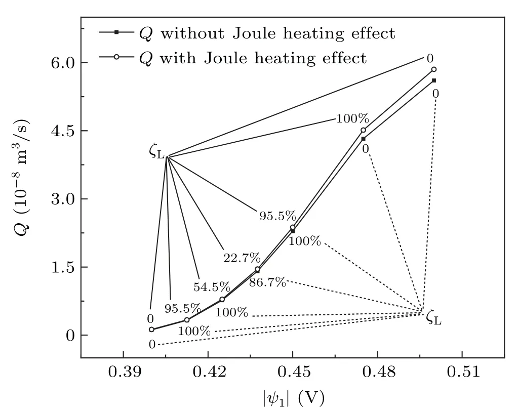
Fig.10. Variation of the channel flux Q and the separation rate ζL with the modulating voltage ψ1 when the driving voltage and other conditions remain constant(ϕ1=70 V,σf0=0.1 S/m,h=300 W/(m2·K)).
3.6. Effect of the solution conductivity
It is well known that the conductivity of a solution has a great influence on the Joule heating effect in electrokinetic flow. When the applied voltages (ϕ1= 70 V,ψ1=−0.425 V) and the convective heat transfer coefficient (h=300 W/(m2·K)) remain unchanged, the channel flux isQ=7.6826×10⁻⁹m3/s and the separation rate isζL=100%without considering the Joule heating effect. When the Joule heating effect is considered, the ability of the vortices to trap the particles is enhanced, and small particles can be captured by the vortices. The heating sourceσf0(E·E)is proportional to the initial conductivity of the fluidσf0. Accordingly,the Joule heating effect is stronger with a higher fluid conductivity. As shown in Fig.11(a),when the initial conductivity of fluidσf0increases,the maximum temperatureTmaxincreases. According to Eq. (9), since the solution viscosity decreases with an increasing temperature,the channel flux slightly increases correspondingly,as shown in Fig.11(b). The modification of the flow field is more significant as the Joule heating effect increases; thus, the particles can get closer to the modulating electrodes. The separation rate decreases because an increasing number of small particles are trapped by the vortices with an increasing conductivity,as shown in Fig.11(a).

Fig.11. (a)Variation in the maximum temperature Tmax and separation rate ζL with the initial conductivity of solution σf0 and(b)increases in the channel flux rate(QJ −QWJ)/QWJ×100%with the initial conductivity of solution σf0, while the other conditions remain unchanged. Here, QJ is the channel flux with the Joule heating effect, and QWJ is the channel flux without the Joule heating effect.
3.7. Effect of the convective heat transfer coefficient
It is well known that the convective heat transfer coefficient of the channel wallhhas a great impact on the temperature distribution. When the applied voltages(ϕ1=70 V,ψ1=−0.425 V)and the convection of the solution(σf0=0.1 S/m)remain unchanged,the channel flux isQ=7.6826×10⁻⁹m3/s and the separation rate isζL=100%without the Joule heating effect. According to the results of Subsection 3.4, the Joule heating effect can improve the ability of the vortices to capture the particles. As the Joule heating effect is included, the Joule heating effect is inversely proportional to the convective heat transfer coefficient of the channel wall. As shown in Fig.12(a),whenhincreases,the Joule heating effect reduced,and the maximum temperature decreases. It is noticeable that the ability of the vortices to capture particles decreases with the reduced Joule heating effect. Consequently, more small particles move downstream of the channel, and the separation rate increases. Moreover, the channel fluxQchanges slightly with an increasing convective heat transfer coefficient,as shown in Fig.12(b).

Fig.12. (a)Variation in the maximum temperature Tmax and separation rate ζL with the convective heat transfer coefficient of the channel wall h and(b) increasing rate of channel flux (QJ −QWJ)/QWJ×100% with the convective heat transfer coefficient of the channel wall h, while the electric field and other conditions remain unchanged (ϕ1 =70 V, ψ1 =−0.425 V,σf0 =0.1 S/m). Here, QJ is the channel flux with the Joule heating effect,and QWJ is the channel flux without the Joule heating effect.
3.8. Effect of modulating electrode length

Fig. 13. (a) Variation in channel flux Q and separation rate ζL with the length of the modulating voltage Le,(b)variation in the maximum temperature Tmax with the length of the modulating voltage Le, and (c) temperature distribution along the channel centerline with different modulating electrode lengths; the electric field and other conditions remain constant (ϕ1 =70 V,ψ1=−0.425 V,σf0=0.1 S/m,h=300 W/(m2·K)).
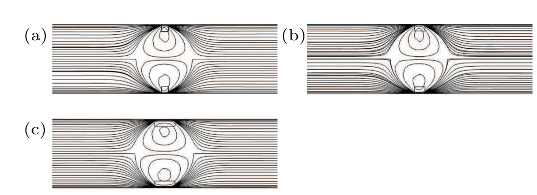
Fig.14. Schematic diagram showing the flow field with different lengths of modulating electrodes Le when the electric field and other conditions keep constant(ϕ1=70 V,ψ1=−0.425 V,σf0=0.1 S/m,h=300 W/(m2·K)),(a)Le=10µm,(b)Le=17µm,and(c)Le=30µm.
It is clear that the length of the modulating electrode has an influence on the local modulating electric field. When the length of the modulating electrodes increase with other invariable conditions, the influence of the regulating range of the local modulating field is studied in this subsection. As shown in Fig.14,the range of the affected flow field generated by the modulating field is wider as the length of the modulating electrode increases. Since the electric forceρeEis also strengthened with an increasing length of modulating electrodes, the channel fluxQincreases, as shown in Fig.13(a). The hydrodynamic force increases with a higher flow rate. However,the inhomogeneity of the local electric field is not affected by the change of the length of the modulating electrode,which means that the nDEP force is unchanged. The trapping ability of the vortices to particles is weakened when the modulating electrode length increases, so the small particles are more easily carried downstream of the channel. As the modulating electrodes are longer,the large particles can be transported downstream of the channel;thus,the separation rate decreases up toζL=0. When the Joule heating effect is considered,the channel flux also increases. The ability of the vortices to capture particles is enhanced. However, when the length of the modulating electrodes exceedsLe=20 µm, the separation rate isζL=0 as the large particles can be carried downstream, as shown in Fig.13(a). The Joule heating effect is stronger as the region of the local electric field is broader with longer modulating electrodes, and the increase in the maximum temperature is slight, as shown in Fig. 13(b), because the maximum temperature is measured at the midpoint of the modulating electrodes. The variation in temperature in the channel is obvious,as observed in Fig.13(c),and the temperature is higher with the increasing length of the modulating electrodes. The Joule heating effect becomes important with the longer modulating electrodes; hence, short modulating electrodes should be selected to avoid higher temperatures. However,considering the production difficulty and separation effect in practical applications, a favorable length of the modulating electrode can beLe=17µm.
3.9. Effect of channel width
In this subsection,the influence of channel width is studied. When the width of the channel is increased as the electric field and other conditions remain unchanged,the channel fluxQincreases, as shown in Fig. 15(a), and the hydrodynamic force is also enhanced,but the nDEP force is constant for the unchanging local electric field. When the channel becomes wider,the trapping ability of the vortices for the particles decreases,and the separation rate increases as more small particles enter the channel downstream with the flow. As the width of the channel increases further,the large particles are carried downstream of the channel and the separation rate could reduce up to 0, as shown in Fig. 15(a). With the Joule heating effect,the capturing ability of the vortices to particles improves,and the channel flux increases. Since the local electric field does not unchanged with the channel width, the maximum temperatureTmax, which is measured at the midpoint of the modulating electrode, remains unchanged, as shown in Fig. 15(b). It is noticeable that the temperature rises in the channel when the channel becomes narrow, as shown in Fig.15(c).
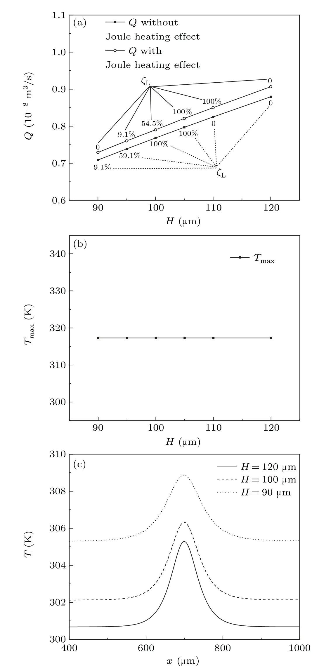
Fig. 15. (a) Variation in the channel flux Q and separation rate ζL with the width of the channel H, (b)variation in the maximum temperature Tmax with the width of the channel H, and (c) distribution of temperature along the channel centerline with different channel widths; the electric field and other conditions remain constant(ϕ1=70 V,ψ1=−0.425 V,σf0=0.1 S/m,h=300 W/(m2·K),Le=17µm).
4. Concluding remarks
In this paper,the effect of Joule heating on the capability of trapping particles with vortices is studied.Two symmetrical vortices are created as a pair of regulating electrodes symmetrically embedded in the channel wall. The results demonstrate that the Joule heating effect is caused by the local electric field,and non-uniform temperature distribution exists in the channel because of the Joule heating effect. It is important that the maximum temperature is at the midpoint of the modulating electrodes. When the Joule heating effect is considered,the channel flux is slightly promoted with an increasing fluid temperature. The particles can get closer to the modulating electrode during its transport, thus the ability of the vortex to trap the particles is improved as an increasing negative DEP force is exerted on those particles. The separation efficiency can also be increased and perfect separation can be achieved at a higher channel flux. When the flow velocity is greater due to a stronger Joule heating effect, the ability of the vortices to capture particles is enhanced. Through the study of corresponding parameters, the results show that the temperature changes with the adjusting voltage, and the temperature variation is more sensitive to regulating the modulating field than the driving voltage. Thus, it is easier to attain a better separation effect by regulating the driving voltage. The Joule heating effect is found to be reduced with the decreasing initial conductivity of fluid or the increasing convective heat transfer coefficient of the channel wall,and the particle separation rate is promoted with the decreasing ability of the vortex to capture particles.Finally,the modulating electrode length and channel width can also affect the separation rate and the temperature of fluids,but the both geometric factors have little impact on the maximum temperature of fluids.
猜你喜欢
杂志排行
Chinese Physics B的其它文章
- Numerical investigation on threading dislocation bending with InAs/GaAs quantum dots*
- Connes distance of 2D harmonic oscillators in quantum phase space*
- Effect of external electric field on the terahertz transmission characteristics of electrolyte solutions*
- Classical-field description of Bose-Einstein condensation of parallel light in a nonlinear optical cavity*
- Dense coding capacity in correlated noisy channels with weak measurement*
- Probability density and oscillating period of magnetopolaron in parabolic quantum dot in the presence of Rashba effect and temperature*