Study on the influence of armature on the efficiency of reluctance accelerator
2022-03-10HuiminDengYuWangZhongmingYan
Hui-min Deng, Yu Wang, Zhong-ming Yan
School of Electrical Engineering, Southwest Jiaotong University, Chengdu, 610031, China
Keywords:Reluctance accelerator Armature design Soft magnetic material Magnetic force calculation Energy transformation efficiency
ABSTRACTThe armature is an important part affecting the energy conversion efficiency of a reluctance accelerator.In this paper, six kinds of soft magnetic materials are chosen and four structures are designed for the armature.At first, the circuit and magnetic force are theoretically analyzed.Then the armatures with different materials and structures are used in the simulation, and the performances are compared and analyzed.At last, the experiment verifies the theory analysis and simulation design.It is concluded that the saturation flux density and conductivity of the material are the key factors affecting the armature force, and the optimization of armature structure can effectively restrain the eddy current, reduce negative force and improve efficiency.Compared with cutting slits in solid armatures, laminating the sheets radially can reduce the eddy current more efficiently.Although slitting can prevent the eddy current to a certain extent, meanwhile, it will decrease the magnetic force because of the losing of magnetized volume and the surface area.Hence, choosing the high saturation flux density material and making out the armature with radially_laminated sheets will improve the efficiency of the reluctance accelerator.In this paper,the silicon steel radially_laminated armature is a better choice for the armature design of the reluctance accelerator.
1.Introduction
Compared with railgun,coilgun has the advantages of low wear of the system and long operational lifetime due to no physical contact with the armature [1-3].Coilgun is mainly divided into induction type and reluctance type.Reluctance-type coilgun is also called reluctance accelerator that requires lower current than induction-type to generate appreciable acceleration for the armature, which simplifies the switching circuit, but still exhibits relatively good efficiency than induction-type [2,4,5].The armature used in this accelerator is even smaller [6].The reluctance accelerator has another advantage that can maintain structural reliability and robust performance in hostile environment [2,4].By contrary, the induced eddy current in the armature of induction coilgun will generate a large amount of heat which will lead to degradation in its performance and controllability [2].Therefore,the reluctance accelerator is suitable to be used in the circumstances of low power,simple drive circuit and high requirement for heat dissipation rather than an induction coilgun.Reluctance accelerator can not only be used as a coil gun to accelerate projectiles, but also has been used as a variety of actuators and electromagnetic tools for industrial machinery (e.g a linear reluctance self-oscillating motor for the driving shuttle of a weaving loom or the pneumatic hammer, a reluctance shuttle device, nail-guns,pumps for electrochemists, and many other electromechanical systems)[7-11].
Reluctance accelerator is a device that transforms the electromagnetic energy to mechanical energy, and the conversion efficiency is worthy of discussion.In recent years, many studies have been done to increase its efficiency[2,3,12-25].The armature plays an important role in affecting the energy conversion efficiency of the reluctance accelerator.The armature of reluctance accelerator is ferromagnetic material, which can be conductive or nonconductive.It can be seen from a lot of research that choosing a suitable armature material is crucial for the optimization of the reluctance accelerator.Slade[7]developed a simplified field-based physical model from basic principles and cast in a variational(Lagrangian) form.From the mathematical model, it can be concluded that using an armature with a high saturation flux density is beneficial for improving the energy transfer efficiency,but the initial permeability is not so crucial for that.Slade done simulation and experiment comparison with ferrite and mild steel to verify the effect of saturation flux density of the armature material in his paper.The efficiency reached approximately 9% by using mild steel armature in Slade’s research.But the eddy current was ignored in his research, so there was no analysis on conductivity of the armature in theory model and experiment.Although several methods were put forward to minimize the eddy current in armature, there were no theory, simulation and experiment to support these ideas.Barrera[12]chose three magnetic materials to analyze and compared the effects on energy transfer efficiency of different saturation values.Meanwhile, the method of cutting slits in the armature can reduce the eddy current is verified by experiment in this paper.The maximum efficiency in Barrera’s study is 8.53%.However,the mathematical model used in Barrera’work was that of Slade’s, so there was no physical explanation how the conductivity affect the efficiency in the theory.DALDABAN [13]used AISI1020 and AISI1050 projectiles to compare their performances,and AISI1050 gained a higher muzzle velocity because of its higher permeability.The accelerator of DALDABAN designed gained the efficiency of 2.04% by using three stages.But there was lack of theory analysis and the two materials belongs to one kind of soft magnetic material.The samples are too few, and the comparison result was not significant.Xiang [14]proposed and compared the armatures with three different structures with one kind material to analyze the efficiency and firing accuracy of reluctance accelerator.The maxim efficiency is 2.87%for cylindrical armature with notch.It only proved that slitting can reduce eddy currents.There was also lack of theory analysis and material comparison.The works[15,16]also studied effects of the magnetic material and structure to the energy transfer efficiency.The highest efficiency value (3.01%) is obtained in the with the 8-cm 1050 projectile[16].Lack of enough kinds of material still existed in these studies.Overall, there are some problems in the previous research.The types of armatures were not enough and systematic; the properties of magnetic material was not elaborated or expounded too little; the theory analysis did not involve the influence of the conductivity to the force exerted on the armature;the method to weaken the eddy current in the armature is single, so there was no comparison analysis in the methods.In addition, the factors of armature influencing the efficiency were not comparatively analyzed and not summarized together in only one research.Most of the efficiencies in these studies were below 4%.Only minority were approximately 9% by using a field-concentrating sheath which can increase the efficiency [26].
To choose suitable armature material and structure to improve the energy conversion efficiency, we systematically and comprehensively compare, analyze and summarize the influence of armature on the efficiency of reluctance accelerator.Firstly, the force exerted on the armature is analyzed theoretically,and various factors of the influencing the magnetic force on the armature is studied on the basis of the physical essence.Especially, the calculation of volume force density and the effect of conductivity of the armature on the force are elaborated in detail.Secondly,armatures with six kinds of soft magnetic material and four kinds of structures are chosen, and the impact of the various factors on efficiency is analyzed and compared, and the factors include conductivity,saturation flux density and structure.Through the use of more comprehensive structures and materials than ever before for centralized comparison, this work not only verifies the conclusion of the previous researches by simulation and experiment,but also provides a clearer reference for selecting a suitable armature and improving the energy conversion efficiency.In this paper, the armature made out of radially_laminated silicon steel sheets achieves the most efficiency,and this type of armature has never been designed for the reluctance accelerator in previous researches.The study on the armature can also provide references for the design of other electromagnetic devices using ferromagnetic materials.
2.Theoretical analysis
2.1.Circuit analysis
The model of the reluctance accelerator is shown in Fig.1.The accelerator consists of a drive coil, a tube and a ferromagnetic armature.When the drive coil is energized by the power, the armature is magnetized by the magnetic field.The electromagnetic attraction force will pull the armature into the coil.If the drive coil still has current when the armature passes the middle of the coil,a reverse force will be generated and reduce the speed and suck the projectile back, which is called suck-back effect.So the current must be cut off as soon as possible when the centerlines of the projectile and the drive coils is about to overlap.
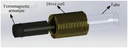
Fig.1.The model of the reluctance accelerator.
An improved discharging circuit is opted as the drive circuit of the reluctance accelerator,which prevents the suck-back effect and increases the efficiency [17], as shown in Fig.2.The whole discharging process contains three steps.The first step, the thyristor THY1 is off and IGBT1 is on, and the drive coil is energized by the capacitor bank.The circuit is modeled as RLC circuit,and Kirchhof’s voltage law is written as
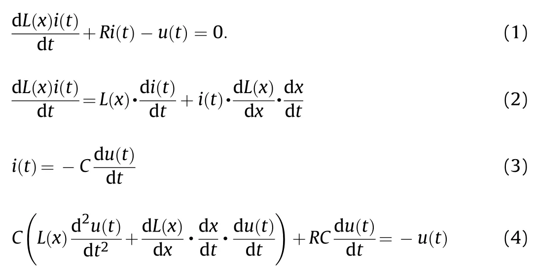
where(x) is the inductance of drive coil, which is a quantity related to the position of armature.is the capacitance of the capacitor bank for discharging.is the resistor of the circuit,()is the voltage of the capacitor bank, and() is the current in coil.
At the second step,the current will flow through1 as soon as the voltage of capacitor decreases to zero,and the current in the coil decays according to the exponential law.The electric equation in this RL circuit can be expressed as
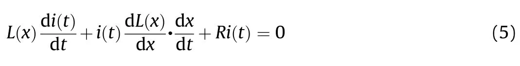

Fig.2.Drive circuit schematic diagram.
At the last step, IGBT1 is turned off and THY1 is switched on when the armature is getting to the center of the coil.The current flows through C2 and charges it.The residual voltage direction of C2 is opposite to that of the initial charging voltage.The circuit in the last step of the discharging process can also be solved by Eq.(4).But the C and()are referred to the capacitance and the voltage of C2,respectively.
2.2.Transient diffusion equations
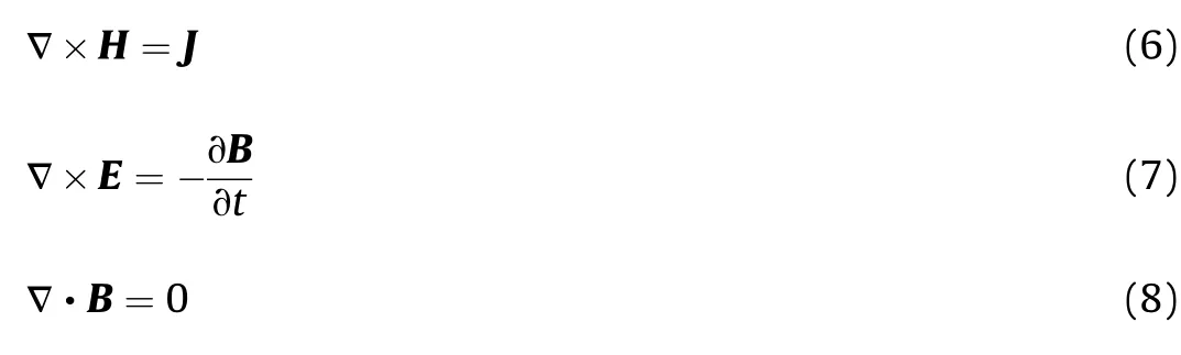
The pulsed magnetic field is quasi-stationary, so the displacement current can be neglected.The Maxwell’s equations in this problem can be written as:
And the constitutive equations are:

where His the magnetic field intensity,Bis the magnetic induction,Eis the electric field intensity, Jis the current density, μis the permeability, which is a function of H, can be written as μ(),σ is the conductivity.
The divergence of a curl is always zero, according to Eq(8),the magnetic induction B can be expressed as the curl of magnetic vector potential A:

The solution domain of the reluctance accelerator includes three regions, which are air, drive coil and armature respectively, as shown in Fig.3.The diffusion equations may be specialized to the varied parts as follows [27]:for the source free air region,
for the linear source region,drive coil part,

for the source free nonlinear eddy current and movable armature region,

Fig.3.Solution domain of the reluctance accelerator.

where μis the permeability of air, Jis the excitation current density in the coil,Jis the induced eddy current in the armature,ν is the velocity of the armature.
2.3.B-H curves interproximation
B-H Curves,which describe the nonlinear relation between the magnetic induction B and the magnetic field intensity H, are used to model ferromagnetic materials in connection with electromagnetic field computation.In our problem, the soft magnetic materials are isotropic, and the hysteresis is neglected.B-H curves are generally established by giving tabulated sets of B-H values which obtained by experimental measurements on ferromagnetic materials.The B-H curves of soft magnetic material are modeled to be single valued in our problem.For computer implementation, it is desirable to model the B-H curve by an appropriate mathematical expression or by suitable numerical method.Interpolation method is generally used to approximate the curve [28,29].The Akima’s interpolation method provides a natural and more suitable procedure for the smooth curve fitting of experimental data [30,31].The approximate B-H curve obtained by this method is monotony,smooth and does not appear unwanted jitter.According to the Akima’s interpolation method, for a set of data points

The interpolation function can be defined as


2.4.Electromagnetic force calculation
The calculation of the magnetic force acting on the current carrying conductor and ferromagnetic objects is of great importance for designing the electric-magnetic energy transformation device, which is the foundation to predict the performance of the device.The force calculation is an important topic in the domain of the numerical computation of electromagnetic fields.The calculation methods of electromagnetic force exerted on armatures were discussed and analyzed comprehensively in many previous literatures[32-47].There are a number of different methods to calculate the magnetic force.
In general,these methods can be classified into two groups.The first group contains the Maxwell stress tensor method and virtualwork principle method.They are used to calculate total force of the objects in the magnetic field.They have more a mathematical than physical meaning.The second group contains the equivalent source methods(equivalent charge or current)and the methods based on Lorentz formula.Some of the time, we need to calculate the local force, and want to understand the physical meaning of the force and the influencing factors, so the second group of calculation methods is appropriate.
According to electromagnetic theory,the force of magnetic field on current carrying conductor and ferromagnetic object is transmitted through medium.There is stress in magnetic medium(vacuum or air),that is,the tension along the magnetic line of force and the direction perpendicular to the magnetic line of force.If we select a closed surface lying in the air to enclose the armature of interest,the electromagnetic stress acting on any unit surface area in vacuum medium is
where fdenotes the surface force density, Bthe magnetic induction on the air side, n is a unit vector normal to the surface element.This method is called Maxwell stress tensor.The surface density of the force in the normal direction is:

where μand μdenotes the permeability of air and magnetic material,andrepresent the normal and tangential component of magnetic induction on the air side.
Maxwell stress tensor and Virtual-work principle are closely related.Virtual work principle is an alternative method for the former one.When the B-H relationship is nonlinear,the magnetic energy and force is:

The armature of the reluctance accelerator is ferromagnetic material, which may or may not be conductive.According to the theory of electrodynamics, electromagnetic material in the transient electromagnetic field is exerted not only by the magnetic force caused by the magnetization but also by the Lorentz force caused by the induced current in the conductor.When the pulsed current flows through the drive coil, the eddy current is simultaneously induced in the conductive armature.The volume magnetic force density on the armature can be expressed by the resultant force of two parts of forces.To analyze the local force volume density, the second group of methods is needed.They are magnetic charge method,magnetizing current method,Kelvin force density method,Korteweg-Helmholtz force density method, etc.The volume force density calculation methods are listed in Table 1.

where Jis eddy current density in armature,Jis the magnetizing current density,B is magnetic flux density,Mis the magnetization,μ is permeability of the armature,αrepresents material properties,such as density and magnetic permeability that varies with position.In our problem,αstands for magnetic permeability.The first term in these equations in Table 1 stands for the Lorentz force density, which denotes the force per unit volume on a currentcarrying conductor in a magnetic field, marked as f.The secondterm is the magnetization force density, marked as f.The resultant force applied on the armature is the sum of the two kinds of force.If the ferromagnetic material is nonconductive, the first term can be neglected.
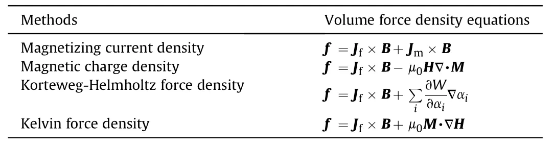
Table 1Methods of calculation of volume force density.
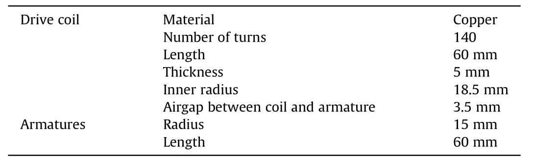
Table 2Transient simulation model dimensions.
When the projectile enters the coil, the Lorentz force and the magnetization force are repulsive and attractive respectively.For our problem,Lorentz force will decrease the speed of the armature and reduce the efficiency of the energy conversion.According to Eq.(10), eddy current density in the armature is proportional to conductivity.Hence,to choose a low conductive material or to optimize the construction of the armature to reduce the eddy current density can improve the armature performance.So this equation provides reference to choose and design the armature.
To calculate the field values, the boundary conditions must be satisfied on the interfaces between different media [42].

When there is no field source on the boundary.
2.5.Kinematic equations
For the reluctance accelerator moving system, only the axial motion is concerned, and only the longitudinal force needs to be calculated.The kinematic equations of the armature are written as:
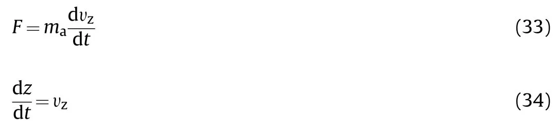
whereis the mass of the armature, υis the-directed (axial)velocity, andis the position of the armature respect to the start point.The energy transformation efficiency of the reluctance accelerator can be expressed as
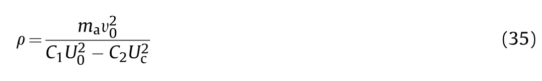
whereis the capacitance of C1 in Fig.2,is the initial voltage of C1,is the capacitance of C2 in Fig.2.is the charging voltage of C2.υis the muzzle velocity of the armature.
3.Simulation analysis
To simulate the motion of the accelerator, the finite element method (FEM) simulation software ANSYS Maxwell is utilized.In this section, the simulation model is described; the results and performances of different armature are compared and analyzed.
3.1.Simulation model
Due to the special structure of the armature, 3-D simulation model is used and shown in Fig.3.Table 2 exhibits the dimensions of the simulation model.In order to design an armature which can improve the efficiency of the reluctance accelerator,the influences of material and structure must be analyzed.
Six kinds of soft magnetic materials are chosen here, which almost cover the kinds commonly used in motors.They are silicon steel sheet (20JNEH1200), iron (DT4C), iron-colbat alloy (1J27),amorphous alloy(1K101),permalloy(1J50),and ferrite(PC40).The basic electromagnetic properties of these materials are listed in Table 3.Bs represents the saturation flux density.The B-H curves and μ-H curves of these materials are shown in Fig.4.
Based on the electric property of the soft magnetic materials and the theory analysis above,the conductive armatures will be exerted by the Lorentz force caused by the eddy current, and the energy conversion efficiency will be lowered down by this negative force.In order to reduce the Lorentz force, some measures have to be taken to restrain the eddy current.Therefore, four kinds of structures are designed here to compare.The details of the classification of armature structures are shown in Table 4.

Table 3Electromagnetic properties of materials of armature.

Table 4Classifications of the armature structure.
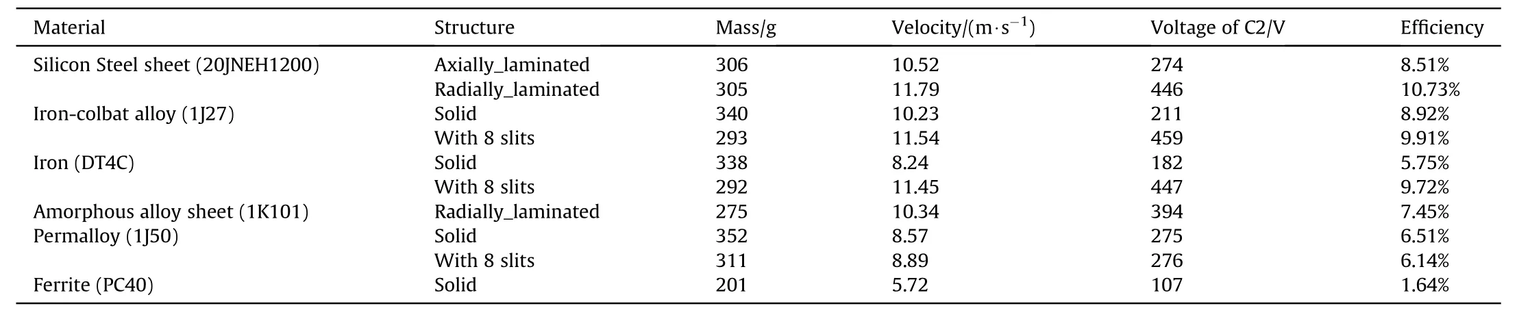
Table 5Simulated results of different Armatures.
The six materials are divided into two groups according to the manufacture form.One group is the form of rod, the other is the form of sheet.For the form of rod, we choose four different materials, all of which are processed into solid cylinder, which is the basic structure without modification.Besides ferrite armature(conductivity can be ignored),materials with obvious conductivity are cut with 8 slits from the edge to the center around the solid cylinder.The width of the slit is 1 mm,and the depth is 12 mm.As a measure to reduce eddy current, slitting is used to compare with the solid cylinder structure.
For the form of sheet, we choose two materials of silicon steel and amorphous alloy.They are both radially laminated to break the paths which eddy currents can flow through,because the sheets are insulated from each other.Meanwhile, the silicon steel sheets are also axially laminated,the purpose of which is to compare with the radially lamination structure.Although the axially_lamination cannot prevent the formation of eddy current, this structure can reduce the eddy current density of the whole armature because of the insulating material on the sheet.There are not only comparisons of different materials based on the same structure but also comparisons of different structures based on the same material in this study.
The initial position,which is the distance from the centerline of drive coil to the front-end of the armature will affect the performance of the accelerator, and an optimal position can make the armature gain the maximum kinetic energy[24,25].Comparing theresults by several simulations, the values of the optimal initial position in this model of different armatures are set between -13mm and -15 mm.The external circuit used in this simulation is shown in Fig.2.The capacitances of C1 and C2 are 1600 μF and 25 μF,respectively.The initial voltage of the capacitor bank is set to 500 V.
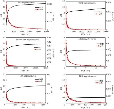
Fig.4.The B-H curves and μ-H curves of different materials.
3.2.Simulation results analysis
The simulation results are listed in Table 5.From the results,we can find that the radially_laminated silicon steel sheets have the highest efficiency.Ferrite has the lowest efficiency.The axially laminated structure has a lower efficiency than the radially laminated structure.1J27 and DT4C cylinder with slits have a higher efficiency than solid structure.But the 1J50 has the opposite phenomenon.Next,we will analyze the influence of each factor on the efficiency from the material properties (electric conductivity and saturation flux density)and structure of the armatures.

Fig.5.The forces on the armatures with different structures and different materials.
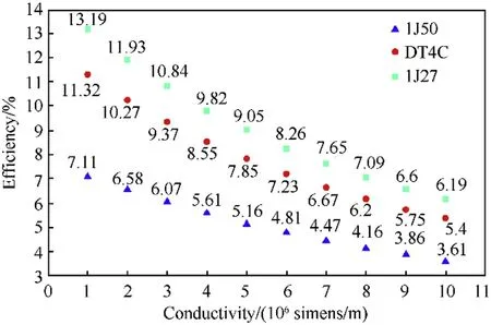
Fig.6.Simulated efficiencies on different assumed conducivities of 1J50, DT4C, and 1J27.
To analyze the influence of the conductivity of the armature to the force, we simulated and compared the force exerted on the armature by assuming the conductivity of some materials to be zero.The simulation results of forces are shown in Fig.5.1J27 with no conductivity gains a one and a half times larger force than with conductivity.DT4C with no conductivity gains a twice larger force than with conductivity.1J50 with no conductivity also gains a larger force than with conductivity.Combined with the theory analysis above, these phenomena are caused by the Lorentz force which is generated by eddy current in the conductive armature.According to the theoretical analysis above, higher conductivity will lead to larger eddy current density and greater Lorentz force.Therefore,the conductivity of the material will decrease the resultant force.
After analyzing the influence of conductivity on the force, we continue to study the influence of conductivity on efficiency.We selected three materials of 1J50, DT4C, and 1J27.10 values are uniformly taken between 10Simens/m and 10Simens/m as the hypothetical conductivity,and are simulated by using our model.The simulation results are shown in Fig.6.It can be seen that the efficiency increases with the decrease of conductivity, and the efficiency will increase about 7%-10%if the conductivity decreases 10Simens/m.When the conductivity is 10Simens/m,the efficiency of 1J27 will reach to 13.19%which is twice when its conductivity is 10Simens/m.The other two materials have the same phenomenon.
fl
In order to analyze the effect of the saturation flux density to the efficiency,three sets of data is simulated assuming these materials are with the same conductivities which are 10Simens/m,5×10Simens/m,and 10Simens/m.The efficiencies of these six kinds of materials are shown in Fig.7.The order of efficiency from low to high is consistent with the order of saturation flux density.The increase in Bs has a significant effect on the improvement of efficiency.Take the two materials with the most significant Bs difference for example,the saturation flux density of 1J27 is 1.85 T larger than that of PC40, and its efficiency is increased by more than 6 times.

Fig.7.The efficiencies of different materials with three same assumed conductivity value.
According to the Professor Slade’s research[48].

whereis the radius of the armature,is magnetic flux density in-direction,is the saturation flux density of the armature.The force will only depend on the saturation flux density, when the armature is saturated.The armature will spend most of its time in saturated state because of the high magnetic field strength generated by the driving current.It can be seen from Fig.5, due to the lowest saturation flux density, the ferrite armature gains the smallest force despite owing the lowest conductivity.Hence,saturation flux density is an important index to choose the material of the armature.It can be seen from Figs.4 and 5, the magnetic permeability has little influence in the efficiency, because the reluctance accelerator spends very short time in low current during the whole launching process.
In practical application, high saturation flux density and low conductivity cannot be satisfied at the same time in one kind of material,so it is necessary to take some structural measures for the armature to decrease the eddy current density.
Slitting in the armature is one of the methods to restrain the eddy current.The 1J27, DT4C, and 1J50 armatures were all cut by eight slits, and the eddy current densities of armatures sections with two different structures are shown in Fig.8.It can be seen from Fig.8 that slitting can indeed cut off the flow of eddy current and reduce the current densities efficiently.According to the force analysis,the Lorentz force can be restrained and the efficiency can be improved.However, according to the relationship between magnetization force and magnetizing volume, the magnetization volume will be lost by slitting.When the Lorentz force is reduced,the magnetization force will be reduced simultaneously.Therefore,1J27 with the highest magnetic saturation strength does not achieve the highest efficiency after slitting.On the contrary,1J50 with slits achieves a lower efficiency than solid cylinder.
Therefore,slitting is one of the effective methods to reduce the eddy current density.For materials with high conductivity,slitting is also one of the effective methods to improve the efficiency, e.g 1J27 and DT4C.However, for materials with lower conductivity,slitting may reduce the resultant force and efficiency due to the lost of magnetizing volume, e.g 1J50.
Laminating the ferromagnetic sheets is another effective method to restrain the eddy current.From Fig.5(c)and(d),it can be seen that the lamination structure gains larger force than the solid structure.The solid structures in Fig.5(c) and (d) are postulated.The axial lamination is beneficial to reduce the eddy current density due to the insulating layer between silicon steel sheets,but it is not particularly effective compared with the radial lamination.Because the magnetic flux density in the rolling direction of silicon steel sheet is stronger than other directions, and the eddy current still exist circumferentially as the sheets to be laminated axially,radial lamination is a better structure compared with the axial lamination.

Fig.8.Eddy current density(J)of armatures sections with two different structures of DT4C,1J27,and 1J50.(time=0.5 ms,position=5 mm from the top surface of the armature).
In summary,slitting and laminating are both effective methods to reduce the eddy current.The negative effect of Lorentz force can be minimized by lamination without wasting too much magnetizing volume.Therefore,the material that has ideal saturation flux density and can be made into laminated structure is an ideal option for armature of reluctance accelerator.
4.Experimental research
4.1.Experimental platform construction
The experimental equipment in this paper is composed of a launcher, pulsed power supply, switches, control system, sensor,velocity-measuring system, data acquisition and processing system.The layout of the experimental equipment is shown in Fig.9.The launcher consists of an armature, a former, a drive coil.The cylindrical armatures used in the experiment are shown in Fig.10.The materials and structures are described in Tables 3 and 4.The edge cutting of laminations and slitting of armatures are machined by wire cutting technology.The driving coil is winded with 1.5-mm enameled copper wires on the skeleton made of nylon.A cylindrical hollow was dug in the nylon skeleton, which provides the motion track for the armature.
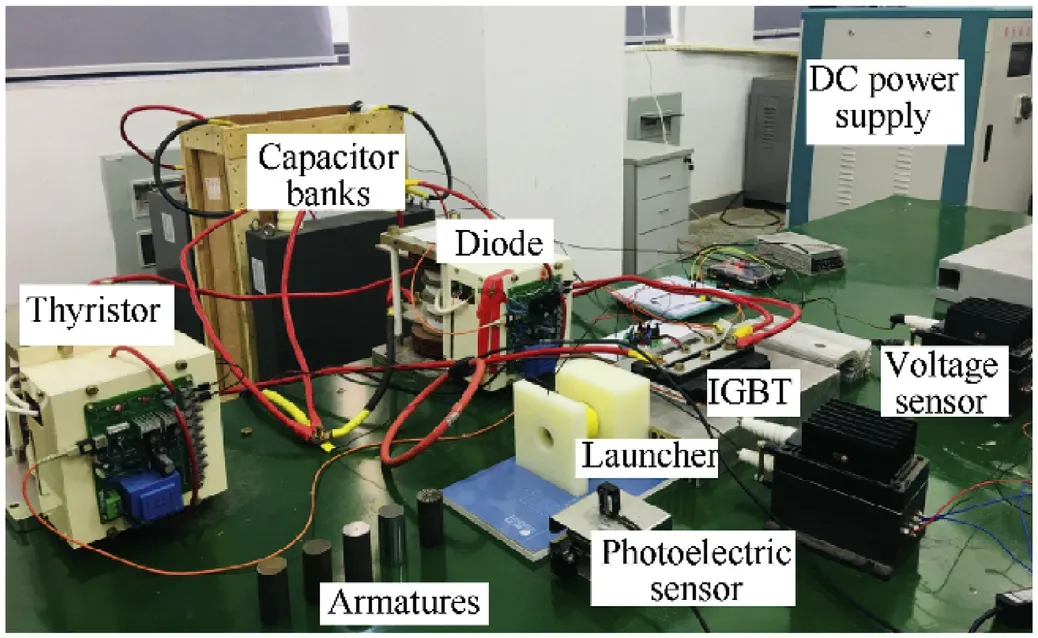
Fig.9.Experimental layout of the reluctance accelerator.
The dimensions of the drive coil and the armature are shown in Table 2.The inductance and resistance value of the drive coil are measured by LCR meter.The inductance and resistance value are 403.58 μH and 228.94 mΩ.In this experiment, the charging voltages for the capacitor bank are set as 500 V.The discharging capacitance and reversed charging capacitor are 1600 μF and 25 μF.The selected capacitor and voltage are all based on our existing experimental condition.

Fig.10.Different amatures with various materials and structures.
4.2.Experimental results analysis
The turn off time of IGBT is determined by the time for the armature to reach the middle point of drive coil,thus the armature will gain the best performance.For different armatures,the time to reach the middle of the coil is different.The simulation and experimental curves of currents with different armatures are shown in Fig.11.Good agreement between the experiment and the simulation is both observed in Fig.11.The experimental results of different armatures are shown in Table 6, which is in good agreement with simulation results.Experiment reveals the same phenomena as simulation, so it can draw the same conclusions as simulation described above.This demonstrates that the theory and simulation analysis is correct and the design is reasonable.
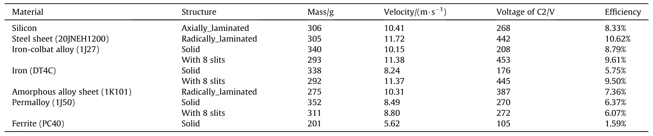
Table 6Experimental results of different Armatures.

Fig.11.Simulation and Experimental currents in drive coil by using different armatures.
5.Conclusion
According to the theory,simulation,and experimental analysis,the conductivity of the armature,the saturation flux density and its structure design are all the factors that affect the efficiency of the reluctance accelerator.The saturation flux density is the most important factor,and the conductivity will generate negative force to decrease the efficiency.Although slitting can reduce the Lorentz force,it cannot completely eliminate the induced eddy current,and the slitting will decrease the magnetizing volume and the force surface area.The armature made out of radially-laminated silicon steel sheet with high saturation flux density is the most suitable material and structure for the reluctance armature in this research.Its efficiency reaches to 10.62%in the experiment and is higher than that in previous researches[7,12-16].It can be concluded that the high saturation flux density is the necessary requirement to choose the armature material.Meanwhile, laminating method is more efficient to restrain the eddy current to improve the efficiency compared with the slitting one.
With the development of science technology, materials with higher saturation flux density and low conductivity may be appear in the future,which will simply the fabrication of the armature and improve the efficiency of the reluctance accelerator.Even so, the methods used here and conclusion drawn in this paper also provide a reference for the design of the device that needs electromagnetic force.
The authors declare that they have no known competing financial interests or personal relationships that could have appeared to influence the work reported in this paper.
This work was supported in part by the Fundamental Research Funds for the Central Universities, China [grant number 2682020GF03]and in part by the Foundation of Key Laboratory of Magnetic Suspension Technology and Maglev Vehicle, Ministry of Education, China.
杂志排行

Defence Technology的其它文章
- A fast and accurate model for the creation of explosion fragments with improved fragment shape and dimensions
- External blast load factors for dome structures based on reliability
- A comparative study of four nonlinear dynamic methods and their applications in classification of ship-radiated noise
- Ignition of nanothermites by a laser diode pulse
- Improving the energy release characteristics of PTFE/Al by doping magnesium hydride
- Buckling analysis of shear deformable composite conical shells reinforced by CNTs subjected to combined loading on the two-parameter elastic foundation