Commissioning of a high-resolution collinear laser spectroscopy apparatus with a laser ablation ion source
2022-02-23ShiWeiBaiXiaoFeiYangShuJingWangYongChaoLiuPengZhangYinShenLiuHanRuiHuYangFanGuoJinWangZeYuDuZhouYanYunKaiZhangYanLinYeQiTeLiYuChengGeChuangYeHe
Shi-Wei Bai • Xiao-Fei Yang • Shu-Jing Wang • Yong-Chao Liu • Peng Zhang • Yin-Shen Liu • Han-Rui Hu • Yang-Fan Guo • Jin Wang • Ze-Yu Du • Zhou Yan • Yun-Kai Zhang • Yan-Lin Ye • Qi-Te Li • Yu-Cheng Ge • Chuang-Ye He
Abstract Collinear laser spectroscopy is a powerful tool for studying the nuclear spins,electromagnetic moments,and charge radii of exotic nuclei.To study the nuclear properties of unstable nuclei at the Beijing Radioactive Ion-beam Facility (BRIF) and the future High Intensity Heavy-ion Accelerator Facility (HIAF),we developed a collinear laser spectroscopy apparatus integrated with an offline laser ablation ion source and a laser system.The overall performance of this state-of-the-art technique was evaluated,and the system was commissioned using a bunched stable ion beam.The high-resolution optical spectra for the 4s 2S1/2 →4p 2P3/2 (D2)ionic transition of 40,42,44,48Ca isotopes were successfully measured.The extracted isotope shifts relative to 40Ca showed excellent agreement with the literature values.This system is now ready for use at radioactive ion beam facilities such as the BRIF and paves the way for the further development of higher-sensitivity collinear resonance ionization spectroscopy techniques.
Keywords Nuclear properties · Collinear laser spectroscopy · Laser-ablation ion source · Photon detection · Isotope shift
1 Introduction
Understanding the nuclear structural evolution of shortlived exotic nuclei in the vicinity of proton and neutron driplines is one of the main topics in current nuclear physics research,which has triggered the continuous development of various experimental techniques and theoretical approaches [1,2].The static properties of the ground and isomeric states of unstable nuclei are indispensable for studying exotic nuclear structures [3-5] and present a stringent test for nuclear models [6,7].Collinear laser spectroscopy (CLS) has been proven to be a powerful tool to measure multiple nuclear properties of exotic nuclei [8,9].In this technique,the hyperfine structure(hfs)and isotope shift due to the interaction between the atomic nucleus and surrounding electrons are probed to precisely extract the nuclear spins(I),magnetic dipole moments(μ),electric quadrupole moments (Qs),and changes in the mean square charge radii (δ〈r2〉) of an isotopic chain in a nuclear model-independent manner.
Along with the observation of unexpected nuclear phenomena in short-lived exotic nuclei,the upgrading of existing radioactive ion beam (RIB) facilities and development of next-generation facilities are motivated by the goal of producing more exotic radioactive beams.Meanwhile,considerable efforts have been made continuously to enhance the experimental sensitivity and precision of the CLS technique [10,11] to facilitate further studies on exotic nuclei.To date,this experimental technique has been established at various RIB facilities such as ISOLDE/CERN [12],IGISOL/JYFL [13],ISAC/TRIUMF [14],NSCL/MSU [15],and ALTO [16] and has provided significant inputs for nuclear structure studies and important benchmarks for the development of state-of-the-art nuclear theories [7,17-19].
Two operational RIB facilities are available in China,namely the HIRFL (PF-type) at the IMP in Lanzhou [20,21] and the BRIF (ISOL-type) at the CIAE in Beijing [22,23].These facilities have played a significant role in nuclear physics research [21,22,24-26].To gain access to more rare isotopes,the high-intensity heavy ion accelerator facility (HIAF) [27-30] is under construction,and the Beijing isotope-separation-on-line neutron-rich beam facility (BISOL) [31] is being planned.These two facilities offer new opportunities for nuclear physics studies in the near future.However,the well-established CLS technique has not been implemented at these domestic RIB facilities so far.Therefore,to take full advantage of the short-lived isotopes available at these facilities,we have,as a first stage,developed a CLS device combined with an offline laser ablation ion source to fully master the laser spectroscopy technique for the measurement of nuclear properties.This integrated system will also pave the way toward the further development of high-sensitivity collinear resonance ionization spectroscopy for exploring more exotic cases.
Here,we present the details of the newly developed CLS apparatus,which includes a laser ablation ion source with a HV platform up to 30 kV,a beamline with a photo-detection system,a laser system,and a data acquisition system.The first commissioning experiment was successfully performed to probe the 4s2S1/2→4p2P3/2(D2) ionic transition of Ca in ion bunches(with about 10 μs temporal length) generated by the laser ablation ion source.Highresolution optical spectra of four stable40,42,44,48Ca isotopes were measured with a typical linewidth of about 55 MHz,which is comparable to those of well-established standard CLS setups worldwide [6,15,32].The isotope shifts of42,44,48Ca isotopes,that is the difference in the resonance frequencies of isotopes with the mass numbers ofAand 40,δν40,A=νA-ν40,were extracted and found to be in excellent agreement with the literature values [6,33,34].
2 Collinear laser spectroscopy system
Figure 1 shows a detailed sketch of the CLS apparatus,laser ablation ion source,and laser system.The whole setup was constructed in accordance with the ConFlat(CF)standard for high-vacuum conditions,which is currently~10-8mbar,so that the high-sensitivity collinear resonance ionization spectroscopy setup can be subsequently implemented.The hfs spectra of stable ion beams produced by the ion source can be measured with high resolution using the current system.In brief,the bunched ion beam extracted from the laser ablation target (solid material) is accelerated to up to 30 keV.After a 90°electrostatic deflection,the ion bunch is delivered into the CLS beamline,where it is anti-collinearly overlapped with a continuous wave(cw)laser beam.The velocity of the ions can be tuned by applying a scanning voltage to the electrode in the interaction region.The fluorescence photons emitted from the laser-excited ions are collected and recorded by the photon detection and data acquisition systems as a function of the tuning voltage.To probe transitions from neutral atoms,a charge exchange cell (CEC,see Fig.1) is required,and the scanning voltage is applied to an electrode upstream of the CEC.However,the CEC part will not be introduced here,and we will focus mainly on the Ca ion beam measurement.The functional details of the individual parts are introduced in the following sections.
2.1 Laser ablation ion source
The laser ablation ion source was developed to produce stable ion beams of a wide range of elements with energies of up to 30 keV [32,35].Using the pulsed-laser ablation process,bunched ion beams with a typical temporal length of approximately 10 μs,high ion intensity,and low energy spread can be generated.These features of the ion beam make it suitable for the optimization and commissioning of CLS system and future resonance ionization spectroscopy,the development of laser excitation and ionization schemes [35],and the measurement of the atomic hfs parameters of stable isotopes [36].
The inner structure of the ion source is illustrated in Fig.1(bottom left inset).A 532-nm Nd:YAG laser(Litron TRLi 250-100) operated at 100 Hz repetition rate with an approximately 8 ns pulse width is employed for ablating the solid target.The target holder is tilted at 45°with respect to the laser and ion beams.The pulsed laser beam is focused onto the target material at a diameter of approximately 1 mm.The ions generated at the ablation area are extracted and refocused with a multiple-step extraction system,which consists of the first extraction electrode(Ext.1),the first einzel lens(L1),and the second extraction electrode (Ext.2).A negative potential (of up to 6 kV)relative to the platform potentialU0can be applied independently to these electrodes.The extracted ions are then transported to the third extraction electrode (Ext.3) at ground potential and simultaneously accelerated to the final energy of up to 30 keV.The transportation of the accelerated ion beam can be further corrected by a group of horizontal and vertical steerers,and the second einzel lens(L2) before the beam are directed into the CLS beamline by a pair of 90°bender plates.

Fig.1 (Color online) Schematic view of the CLS device,the electrod es of the laser ablation ion source(bottom left inset),and the adopted laser system (top right inset).Stable ion bunches with up to 30 keV energy can be delivered into the beamline and overlapped with a continuous-wave frequency-tunable laser beam in an anticollinear geometry.The ion beam velocity or laser frequency is tuned to resonantly excite the ions in the interaction zone.Fluorescence photons emitted from the excited ions are collected by the photon detection system.See text for more details
As mentioned above,the voltages applied to the electrodes (Ext.1,L1,and Ext.2) are added on top of the acceleration potentialU0.Therefore,as shown in Fig.2,a high-voltage(HV)platform and a HV cage(indicated by a dashed line) were built in accordance with safety guidelines.The acceleration potentialU0is provided by a highprecision DC power supply (Heinzinger PNChp 40000-15pos),which has a ripple of <0.001% and longterm stability of <0.001% over 8 h.ThisU0potential is directly applied to the first CF 6-way cross chamber (light red in Fig.2)of the ion source,which is fully isolated from the second 6-way cross at the ground potential(light green in Fig.2) by a CF-flanged vacuum ceramic break.A multichannel HV power supply module(iseg EHS 80-60n)denoted as power supply B is installed in a HV crate (iseg ECH224) to control the negative potential of the three electrodes (Ext.1,L1,and Ext.2) inside the first 6-way cross.Power supply B is remotely controlled outside the HV cage via an optical link (PEAK-System Technik,PCAN-LWL)for HV isolation and a USB adapter(PEAKSystem Technik,PCAN-USB).An isolation transformer(50 kV) is used to isolate the high voltage (U0) from the ground potential and to provide 220 VAC to power supply B.To determine the energy of the ion beam for the hfs measurement,the acceleration potentialU0is recorded in real time using a Keysight 34470A multimeter combined with a 1:1000 voltage divider (Ohm-labs,KV-30A).

Fig.2 (Color online) Schematic diagram of the high voltage system for the laser ablation ion source,which can be operated at 0-30 kV
2.2 Ion beam transport
The ion bunches are transported through the CLS beamline (approximately 4 m long) using a series of electrostatic optics elements comprising two sets ofx-ysteerers and two quadrupole triplets (QT1 and QT2) lens,as shown in Fig.1.Thex-ysteerer electrodes are used to align the ion beam with the central axis of the beamline,and the QT lenses are used to control the beam spot.Ion beam diagnostic components comprising three Faraday cups (FC1,FC2-m,and FC3) with a secondary electron suppressor,an iris diaphragm,and an ion detector (ETP,14924 MagneTOF Mini) are used to monitor the beam position,intensity,and size.The iris diaphragm with a tunable diameter of 0-20 mm is placed in front of FC2-m(a multi-channel FC) to align the central axes of the ion and laser beams,which can also serve as a simple annular FC to measure the ion beam current and size [37].The FC ion beam current is recorded using a Keithley 6485 picoammeter.The potentials applied to the ion optics are provided by the ± 6 kV HV modules in combination with a HV crate (iseg ECH238).The output voltage of the HV power supply can be controlled remotely using a program written in Python.The program is also used to visualize the ion beam current for the optimization of the ion beam transmission through the CLS beamline.The MagneTOF ion detector is installed at the end of the beamline to monitor the relative intensity variation and to measure the time of flight (TOF) of the ion beams.
2.3 Photon detection system
Figure 3 shows the schematic diagram of the photondetection system.The system consists of a 5-way cross interaction chamber in which the laser beam interacts with the atom/ion beam,as well as two identical detection units installed perpendicularly to the CLS beamline.To suppress the environmental photon background,i.e.,the scattered laser light,the entrance and exit of the interaction chamber are equipped with two aperture arrays that can be dismounted.Each array has four conically shaped apertures with a minimum inner diameter of 10 mm,as shown in Fig.3a.The internal surface of the vacuum chamber is black-coated to further reduce the background from laser scattering.A quartz window (VPZL-600 DU,Kurt J.Lester)with>90%transmission over a wide spectral range of 200-1200 nm is employed to isolate the detection units from the high-vacuum interaction region at approximately 10-8mbar.Note that an isolated electrode tube is mounted in the central axis of the interaction chamber with two open rectangular holes in the direction of the detection unit for the transmission of fluorescence photons.To maintain a uniform field distribution inside the electrode tube (interaction region),the holes are covered with a metallic mesh with a transmission efficiency that exceeds 90%.By applying a scanning voltage to this electrode,the velocity of the ions(not applicable to neutral atoms)can be tuned to match the Doppler-shifted laser frequency for the specific resonance excitation (see Sect.3 for details).
As shown in Fig.3,each detection unit comprises two aspheric lenses(i.e.,a telescope)and a PMT.These lenses,which have a diameter of 100 mm (N-BK7) and a transmission of approximately 90% over a wide range of wavelengths (350-1000 nm),are used to guide the laserinduced fluorescence photons onto the sensitive area of the PMT.A PMT (R943-02,Hamamatsu) assembled with a socket (E2762-506 Hamamatsu) is employed to record the light.The PMT is featured with an ultra-low dark count rate(typical value of 20 s-1at-20°C)and a wide spectral response(160-930 nm),but with a moderate sensitive area of 10×10 mm2.The quantum efficiency of the PMT at 394 nm is approximately 20%.The total geometrical efficiency for fluorescence photons was simulated using a Python-based code [39] modified for the current geometry(Fig.3) and found to be approximately 15% for the two detection units.Because the index of refraction of the aspheric lenses is wavelength-dependent,the distance between the sensitive area of the PMT and the telescope needs to be corrected for different wavelengths associated with specific ionic/atomic transitions to achieve the optimal geometrical efficiency.This correction can be easily performed by changing the thickness of the spacer (e.g.,27.3 mm for 394 nm wavelength),as indicated in Fig.3b.
To achieve a low dark count rate (dozens of counts per second),the R943-02 PMT needs to be maintained at -20--30°C.To cool the GaAs(Cs)photocathode,the head of the PMT is covered by a spiral copper tube denoted as the copper heat exchanger in Fig.3,through which ethanol is circulated by a refrigerant circulator (ECO RE 630S,LAUDA).To prevent the formation of frost/ice on the glass window of the PMTs in the low-temperature environment,dry nitrogen gas is circulated in the system for a few minutes before cooling.The spacer,made of PVC,is also used for thermal isolation between the PMT and lens and can effectively prevent damage to the lens from expansion and contraction caused by temperature variations.As a resultof these treatments,the background rate for the commission measurement described in Sect.3 was about 1 kHz for a 1.2 mW laser beam with a diameter of about 6 mm.It is worth mentioning that the entire detection unit(including the PMT)has proven to be robust and stable despite frequent assembly and disassembly during commissioning.
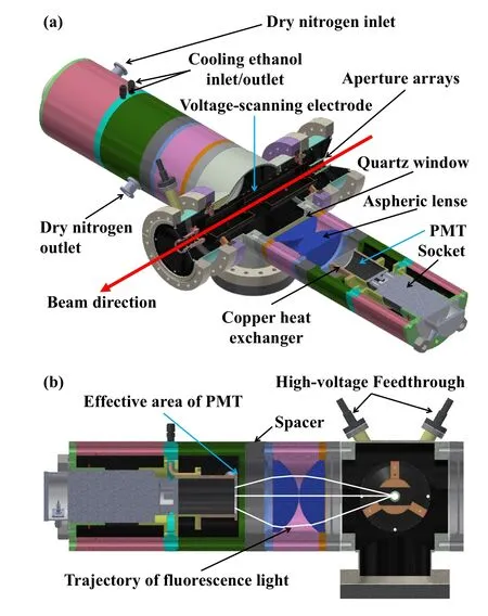
Fig.3 (Color online) a Photon detection system consisting of two sets of detection units,each of which includes a quartz window,two aspheric lens,and a photon-multiplier tube [38].b Schematic view of a detection unit
2.4 Laser system
The laser system used for this CLS setup is partially shown in the top right inset of Fig.1.A continuous-wave(cw) titanium-sapphire (Ti:Sa) laser (Matisse 2TS,Sirah Lasertechnik) is pumped by a 20 W 532 nm laser (Millennia,Spectra-Physics),which can be converted into a dye system via an exchange kit (TIDYECW,Sirah Lasertechnik).This system provides a laser beam with a wavelength range of 650-1020 nm,which can be frequency-doubled with a Wavetrain 2(Sirah Lasertechnik)device to generate second harmonic light covering the wavelength range of 325-510 nm.The Matisse cavity is actively stabilized by the equipped reference cell,reaching a narrow linewidth of<50 kHz.A high-precision wavelength meter (High-Finesse WS8-2)is used to measure the real-time frequency of the fundamental cw light.
The wavelength meter can also be used for the longterm stabilization of the Matisse cavity through a built-in digital interface.To suppress the drift of the wavelength meter (several MHz per day) caused by temperature and pressure fluctuations,a commercial saturation absorption spectroscopy unit is introduced into the system.This unit consists of a tunable diode laser (DLPRO780,TOPTICA Photonics AG),a temperature-controlled vapor cell filled with K,Rb,and Cs(COSY,TOPTICA Photonics AG),and the control and locking electronics.The frequency of the diode laser is locked to one of the hyperfine components of the available alkali atom (e.g.,87Rb).The frequencylocked diode laser is then used to calibrate the wavelength meter when it is used for the long-term stabilization of the Matisse cavity [40],or to correct the drift of the wavelength meter by recording both the frequency-scanned Matisse laser and the frequency-locked diode laser [41].
2.5 Electronics and data acquisition system
The two signals from the PMTs are amplified by a fasttiming amplifier (ORTEC FTA820A) and then discriminated by a constant fraction discriminator (CFD,CAEN model N605).After conversion to TTL logic signals,the converted signals are sent to different channels of a ChronoLogic TimeTagger4-2G time-to-digital converter(TDC)with a 500 ps time resolution.Each event is labeled by a timestamp and tracked to obtain the time-of-flight(TOF) spectrum of the ion bunch.A master TTL signal with a 100 Hz repetition rate(corresponding to a period of 10 ms) labeled asT0=0 μs and generated by a Quantum Composers 9528(QC9528)digital-delay pulse generator is used to externally trigger the 532-nm Nd:YAG laser.The laser pulse used for the ablation ion sources arrives at 490 μs afterT0.Therefore,in consideration of the flight time of the ion bunch from the ion source to the detection region,the start time(trigger)and the time window for the TDC are set asT1=T0+498 μs and ΔT=100 μs,respectively.This time window covers the time required for the bunched beam to traverse the photon detection region.A narrow time gate of approximately 10 μs corresponding to the width of the ion bunch can be further applied to reduce the background count during offline analysis.(This is further discussed in Sect.3.)
The optical hfs spectrum of an isotope can be measured by applying a scanned voltage(ΔU)to the electrode tube in the detection region to probe the optical transition of the ions,or to an electrode upstream of the CEC to probe the optical transition of neutral atoms,while the laser frequency is fixed and stabilized with the wavelength meter.A scanned voltage that can vary from -1 kV to +1 kV is provided by a DC amplifier (Kepco Model BOP 1000DM)with a gain of 100 and a long-term stability of <0.01%over 8 h.The input voltage for the amplifier is provided by a USB device (USB-3106,Measurement Computing).The ΔUapplied to the electrode tube and the starting potentialU0of the ion beam are measured using a Keysight 34470A digital multimeter.
A program written in Python is used for the acquisition system.This program integrates the functions of logging the photon events from the TDC,controlling the scanning voltage via the USB device,recording the frequencies of the Matisse and diode lasers via the wavelength meter,reading the scanned voltage and starting potential of the ions through the multimeter,and displaying the results on a graphical interface.
3 Commissioning test and results
To validate the performance of the CLS system,we performed the first commission experiment on natural40,42,44,48Ca isotopes by probing the 4s2S1/2→4p2P3/2(D2) ionic transition.Stable beams were produced by ablating a calcium target using the 532 nm laser (about 1 mm beam diameter on the target) with an approximate power of 1.5 mJ/pulse.In this test experiment,the extracted ion bunches were accelerated to 20 keV and delivered to the CLS beamline.The ion beam was anticollinearly overlapped with the cw laser beam(Fig.1).The ion and laser beams were aligned using a series of collimators comprising the iris diaphragm,the two 8 mm-diameter collimators at the ends of the CEC,and the two arrays of apertures in the photon-detection region.The laser frequency was fixed at 393.4 nm to match the Doppler-shifted 4s2S1/2→4p2P3/2(D2)ionic transition of Ca isotopes and stabilized using the wavelength meter.The wavelength meter was in turn calibrated using the diode laser,which was locked to a hyperfine component of the87Rb atom.The laser power used was about 1.2 mW,and the diameter of the laser spot was approximately 6 mm.The velocity of the Ca ion in the interaction region was tuned by applying a scanning voltage(ΔU)to the electrode tube(Fig.3).The resulting Doppler-shifted laser frequencyνexperienced by the traveling calcium ion beam in the anti-collinear configuration can be expressed as:

andν0is the fixed laser frequency,Uis the total potential(U=U0+ΔU),andmis the mass of the Ca ion.The optical spectra of Ca isotopes were obtained by counting the emitted fluorescence photons emitted from the resonantly excited ions as a function of the tuning voltage(ΔU).
Figure 4 presents a typical two-dimensional spectrum of the relative laser frequency and TOF.The projection of the photon counts onto thex-andy-axes gives the hfs(Fig.4a)and TOF spectra (Fig.4b),respectively.The typical temporal length of the ion bunch was about 10 μs,but with a visible tail in the higher energy side(the shorter TOF side),as shown in the TOF spectrum.The higher energy tail is probably related to the field distribution within the plasma plume of the ablation process,as described in Refs.[32,35].A TOF correction [35,36] can be applied to compensate the higher energy component of the ion bunches.This gives a similar result to that achieved by simply gating on the main TOF peak,as indicated by the dotted lines in the TOF spectrum.In contrast,the low probability tail in the TOF spectrum was nearly invisible in the measurement of42,44,48Ca,for which the numbers of ions resonantly interacting with the corresponding Doppler-shifted laser frequency was smaller (e.g.,<1 pA)because of the low natural abundance of these isotopes.

Fig.4 Color-coded two-dimensional spectrum of TOF vs.frequency for 40Ca+.The projection of the plot on the x-axis (relative laser frequency)and y-axis(time of flight:TOF)gives the hfs(a)and TOF spectra (b).A typical temporal gate of approximately 10 μs,as indicated by the dotted lines in (b),is applied to obtained the hfs spectrum displayed in(a).The hfs spectrum is fitted with a Voigt line profile (red line)
The high-resolution hfs spectra of40,42,44,48Ca obtained by gating the TOF window,as shown in Fig.4b,are presented in Fig.5 and fitted using a Voigt profile (a convolution of the Gaussian and Lorentzian distributions).The full width at half maximum (FWHM) of the spectra from the Voigt fit is approximately 55 MHz,which is comparable to those of the same type of CLS measurements worldwide [6,15,32].The natural line width calculated from the lifetime of the probed excited state (4p2P3/2) is approximately 25 MHz.Thus,assuming that the Lorentzian component of the Voigt profile is mainly contributed by the natural linewidth,the maximal Gaussian contribution (ΓG) to the FWHM is estimated to be approximately 40 MHz,which is mainly attributed to the energy spread of the offline ion beam.Assuming that the energy spread for the total potentialUof the ion beam isδE,and the resultant Doppler broadening of the spectral line is

Fig.5 The difference in isotope shift of 40,42,44,48Ca between the present experimental results and the literature values [34] for the 4s 2S1/2 →4p 2P3/2 (D2) ionic transition.The optical spectra for 40,42,44,48Ca shown in the insets are fitted with Voigt profiles (red lines)
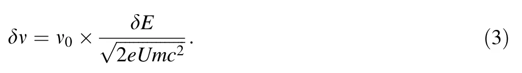
Thus,the 40 MHz Gaussian(ΓG)contribution corresponds to an energy spread of~2 eV in the ion beam,which is mainly due to the fluctuations of the Heinzinger power supply (approximately 200 mV) and the Kepco DC amplifier (approximately 20 mV) and the field distribution at the position of the ablation target.From these highresolution optical spectra (shown in Fig.5),isotope shifts of42,44,48Ca+relative to the reference isotope40Ca+are extracted and found to be in good agreement with the literature values within the error bars [33,34],as displayed in Fig.5 and summarized in Table 1.

Table 1 Isotope shifts(in MHz)of 42,44,48Ca isotopes relative to 40Ca measured for the 4s 2S1/2 →4p 2P3/2 (D2) ionic transition
4 Summary and prospects
In summary,a CLS apparatus integrated with a laser ablation ion source and a frequency-tunable laser system was implemented at Peking University,aiming to study the nuclear properties of unstable nuclei at domestic RIB facilities.The ion source was designed to provide a bunched stable ion beam with a beam energy of up to 30 keV and commissioned to generate a 20 keV bunched stable calcium ion beam.The typical temporal width of the ion bunch was determined to be approximately 10 μs.The apparatus was combined with an anti-collinear 394 nm laser to perform high-resolution measurements of the hfs spectra of stable40,42,44,48Ca isotopes.A narrow linewidth of approximately 55 MHz (FWHM) was achieved,which is comparable to those of the same type of CLS setups worldwide.The Gaussian component of the linewidth(FWHM) was determined to be about 40 MHz,which corresponds to an energy spread of~2 eV for the stable calcium ion beam.The isotope shifts (δν40,A) of42,44,48Ca relative to the reference40Ca+extracted from the obtained hfs spectra are in excellent agreement with the literature values,demonstrating the overall satisfactory performance of the CLS system.
The successful implementation and operation of the system demonstrate the usability of the system for the study of unstable isotopes at RIB facilities such as the BRIF at CIAE.Such online experiments have been scheduled and will be performed in the near future.In addition,further exploration and development of the CLS technique are planned,e.g.,the application of system for atomic hfs spectrum measurement using a charge exchange process and the development of the system toward a resonance ionization spectroscopy measurement.A mass separator and a radio-frequency quadrupole cooler/buncher(RFQ) [10] are also planned for this system.The RFQ system will be important for online experiments,as it will provide bunched ion beams with low energy spread of a few electron volts.
Author ContributionsAll authors contributed to the study conception and design.Experiment was carried out by Shi-Wei Bai,Xiao-Fei Yang,Shu-Jing Wang,Yong-Chao Liu,Peng Zhang,Yin-Shen Liu,Han-Rui Hu,Yang-Fan Guo,Jin Wang,Ze-Yu Du,Zhou Yan,Yunkai Zhang,Yan-Lin Ye and Qi-Te Li.Data analysis was performed by Shi-Wei Bai,Xiao-fei Yang,Shu-Jing Wang,Yong-Chao Liu.The first draft of the manuscript was written by Shi-Wei Bai and Xiao-Fei Yang and all authors commented on previous versions of the manuscript.All authors read and approved the final manuscript.
杂志排行

Nuclear Science and Techniques的其它文章
- Calibrating the linearity between grayscale and element content for X-ray KES imaging of alloys
- High RF power tests of the first 1.3 GHz fundamental power coupler prototypes for the SHINE project
- Studies of the radiation environment on the Mars surface using the Geant4 toolkit
- Evaluation of neutron beam characteristics for D-BNCT01 facility
- Modular next generation fast-neutron detector for portal monitoring
- A novel 4D resolution imaging method for low and medium atomic number objects at the centimeter scale by coincidence detection technique of cosmic-ray muon and its secondary particles