Modular next generation fast-neutron detector for portal monitoring
2022-02-23AboudAhnRogachevJohnsonBishopChristianKoshchiyParkerScriven
E.Aboud • S.Ahn • G.V.Rogachev • V.E.Johnson • J.Bishop • G.Christian • E.Koshchiy • C.E.Parker • D.P.Scriven
Abstract Nuclear nonproliferation is of critical importance for global security.Dangerous fissile materials including highly enriched uranium and weapons-grade plutonium are especially important to detect.Active interrogation techniques may result in much better sensitivity but are difficult with conventional portal monitors that rely on detecting thermal neutrons.Also,most conventional portal monitoring systems rely on 3He,which has a finite and continually decreasing supply.By designing a highly segmented array of organic scintillators,we posit that we can accurately and quickly identify fissile materials,including weapons-grade plutonium and highly enriched uranium,being smuggled.We propose a new design for a fast-neutron detector that overcomes the limitations of the current generation of portal monitors.MCNP6 simulations have been performed in conjunction with the UMPBT statistical model to determine the sensitivity limitations of the proposed detector.Results suggest that the proposed detector may be~10 times more efficient than current-generation thermal neutron detectors and may be able to positively identify a~81 mg 235U source in as little as 192 seconds utilizing active interrogation techniques.
Keywords Fast-neutron detection · Portal monitoring ·Nonproliferation
1 Introduction
Monitoring and halting the movement of unauthorized fissile materials become more important every day,specifically the monitoring of special nuclear materials(SNM).SNMs include239Pu,which is the primary component of weapons-grade plutonium (WGPu),and235U,which is the primary component of highly enriched uranium (HEU).These are radioactive materials and can be identified usingγand neutron detectors.Neutron detection is typically used together withγ-ray monitoring and has an advantage of lower natural background and background induced by radioactive materials used in industry and for medical applications.While WGPu emits significant amount of neutrons and is easier to detect,HEU is particularly challenging because of the low neutron emission rate and due to the fact that low energyγ-rays produced by HEU are relatively easy to shield.Portal monitoring systems often combineγ-ray detectors and neutron detectors.Due to naturally occurring radioactive materials and electronic noise or failures,in radiation portal monitors,the false alarm rate forγ-rays is about 1 in 102and for neutrons about 1 in 104[1].
Current neutron portal monitoring techniques rely heavily on thermal neutron detectors,many of which require3He.3He has applications in many different fields,which has dwindled the increasingly small and finite terrestrial supply[2].Therefore,3He is becoming increasingly expensive and hard to acquire[3,4].Efforts to move away from3He detectors have been an area of interest for more than a decade now.
Generally,SNMs of interest emit neutrons with average energies around 1 MeV -the fast-neutron region.Thermal neutron detectors rely on moderating fast neutrons to detect them,making them indistinguishable from ambient thermal neutrons.These detectors use total counting techniques,which are not position sensitive,to determine an increase in total neutron flux.Detecting only the total neutron flux does not allow them to be sensitive to low-emission fissile materials [5-7].These techniques may also be prone to a high false alarm rate.
Active interrogation techniques can be used to enhance the sensitivity to SNMs such as HEU and WGPu.Fission can be induced in these materials by using a low-energy neutron generator,which utilizes reactions such as7Li(p,n)7Be to produce neutrons.A beam of neutrons with energy around few tens of keV may induce fission in235U and239Pu,while not inducing fission in other isotopes such as238U and232Th.The 60-keV neutron beam produces a small dose and can penetrate bulk materials nearly as well as higher energy neutrons.These low-energy neutrons also lose their energy primarily from elastic collisions rather than reactions or inelastic scattering,creating an easily identifiable neutron background.Previous studies have shown positive results in the identification of small quantities of235U,even when shielded by various materials[8-10].
Recently,there have been attempts to combat the limitations of monitoring systems based on thermal neutron detection [11-13].Hausladen et al.[13] use a segmented array of liquid scintillators with pinhole apertures.PMT after-pulsing caused the liquid scintillator setup to perform worse than expected for neutron andγ-ray pulse shape discrimination.Source identification tested well for highrate sources,but may have difficulty with lower-rate sources.
The approach of Rose et al.[11]uses high-energyγ-ray(Eγ>4 MeV) and fast-neutron active interrogation for spatial imaging.Both the high-energyγrays and the fast neutrons can induce fission in SNM.However,the highintensity background inhibits the ability for direct detection and forces the reliance on secondary reactions,includingβdecay measurements.
Hamel et al.proposed a dual-particle imager (DPI),which can localize both neutrons andγrays.A neutron generator can be used to induce fission and generated neutron events may be discarded using a veto.Image reconstruction was done for both neutrons andγrays using the stochastic origin ensemble statistical technique with the simple backprojection method [14].Image reconstruction can localize the source,but does not reliably identify the source.After localization,source identification is done by analyzing the intensity decay time,while the neutron generator is off.The DPI method can localize and identify SNM,but it requires a multi-step analysis and can take a significant amount of time to identify the source [12].
In order to resolve the existing limitations,we developed a new direct technique for fast-neutron portal monitoring that overcomes the sensitivity limitations of fastneutron thermalization and allows for the use of activeinterrogation techniques.By using small hydrocarbon (pterphenyl) scintillators in a large array,we are able to detect fast neutrons to localize fissile materials,including HEU and WGPu.Our novel design,combined with Bayesian statistical analysis,can perform with an efficiency that is a factor of 12 better than the standard technique based on3He-tubes with a moderator,even for passive interrogation.Insensitivity of this detector to lowenergy neutrons makes it ideal for applications that involve active interrogation.The results described in this paper are intended as proof of viability calculations.A prototype detector is being built and will become available in the near future.The pulse shape discrimination thresholds and time resolution that are used in the simulations presented below were adopted from the already existing basic units of this detector.
2 Simulated detector design
Our proposed design took inspiration from the Gamma-Ray Burst Monitor [15].Similar to their design of identifying an astrophysical event,we utilize small modular crystals to localize a radioactive source.Our conceptual device consists of an array of 2·5×2·5×2·5 cm3p-terphenyl crystals.The detector size is approximately 50×50 cm2in cross section and 25-cm deep -4000 crystals in total.The cross section size was chosen for prototyping purposes,and the depth was chosen to be approximately two mean free paths of a 1 MeV neutron inp-terphenyl (Fig.1).The scintillators are grouped into layers of one crystal in height(Fig.2).Each of the layers is spaced 20 mm apart.The detector is simulated in an idealized geometry where the crystals are packed tightly.

Fig.1 The mean free path of neutrons through p-terphenyl until the first collision for a range of energies up to approximately 11 MeV.The cross section data were taken from ENDF libraries [16,17].At 1 MeV,the mean free path is approximately 12.9 cm

Fig.2 a Exploded CAD drawing of how the scintillators of the proposed device may be distributed.This drawing serves to display the segmentation of the crystals and not the actual geometry of the detector.The cross-sectional face,the side facing the neutron source,is the side facing up.The cross section is 50 cm×50 cm,and the depth is 25 cm.The top third of the drawing shows the compact layer arrangement that the detector would have and the bottom two thirds of the drawing are blown up to show the individual layers.The middle layer is further exploded to show the orientation of individual crystals.They are tightly arranged in each layer as shown in all other layers.b A more realistic view of the neutron detector with appropriate spacing.The cross-sectional face,the face closest to the source,is facing to the left of the page
2.1 p-terphenyl
P-terphenyl [C18H14] is an organic crystalline scintillator.P-terphenyl has been of increased interest in fastneutron detection during the past decade due to its large light output (about 20,000 ph/MeV [18]),excellent time resolution(477(12)ps[19]),fast decay time(14.1 ns[18]),and exceptional pulse shape discrimination (PSD),which gives us confidence for positive neutron identification with a good detection efficiency and fast response times.PSD is necessary to filter outγ-ray events from neutron events in the detector.γrays from ambient background and from various reactions will swamp the detector,but with definitive PSD those events can be filtered out.Prior studies have shown that PSD inp-terphenyl is resolvable down to about the 100 keVee level[20,21].Current testing with apseudo-barconfiguration has shown accurate position resolution down to 300 keVee and PSD down to about 150 keVee[22].In line with the previous studies,the PSD threshold used in the simulations was set to be at about the 100 keVee level.
3 MCNP6 simulations
Monte Carlo N Particle(MCNP6)[23]simulations were performed to estimate the performance of our detector.The simulations generated neutrons from an isotropic235U+n Watt fission source,which peaks at roughly 1 MeV in the neutron energy spectrum,and an ambient neutron background.Note that the ambient neutron background was produced by default functionality [24].For the continental United States,there are 39 grid points where the ambient neutron background was sampled.Due to the proximity,the data point at ground level near New Orleans,Louisiana,was chosen.At this data point,the ambient neutron flux is 0·9907×10-2n/cm2/s.This results in approximately 100 neutrons/s entering our detector from background sources.
Our analysis of the neutron tracks included recoil energy calculations [25] and the PSD threshold explained in Sect.2.1.All events below the PSD threshold were discarded.
4 Data analysis
4.1 Utilization of double-and single-scattering events
The location of the neutron source can be found using segmented neutron detector through observation of neutron double-scattering events (see,for example,Hamel et al.[14]).Application of this technique,in which a neutron needs to produce at least two signals in two separate crystals,in principle,is possible with the proposed detector system.The time of flight(TOF)for a fast neutron between two crystals may be small,but with the time resolution of around 600 ps for thepseudo-bar[22],most double-scattering events are resolvable.Figure 3 shows the simulatedstatistics of time difference between the first and second scattering events of the same neutron from the235U+n source.It is clear that significant fraction of double-scattering events can be resolved.While double-scattering technique offers an advantage of source localization,sole reliance on double-scattering events would reduce efficiency dramatically.Therefore,we will focus on singlescattering events in further discussion.

Fig.3 The time of flight for a single neutron between two scattering events,where the scatterings happen in different crystals.The total neutrons simulated are arbitrary,and the ratio between different bins should be recognized
Our design of a highly segmented crystal array can utilize the density of scatterings in each of the crystals to detect the presence of the source.Crystals closest to the source will see more events than crystals further from the source due to the attenuation in the detector itself,and this effect is the key for identification of the localized source that increases neutron flux from one side of the detector.
4.2 Scattering distribution of directional neutrons and ambient neutron background
The proposed detector is specifically designed to be approximately two mean free paths for a 1-MeV neutron inp-terphenyl (Fig.1).As shown in Fig.4a,when we have a source located in front of the detector,we observe a large number of neutrons scattering in the first half.The number of source neutrons dramatically decreases with respect to the depth of the detector (Fig.5).Figure 4b shows the relatively homogeneous distribution for hits from background neutrons.This background can be well characterized by periodic sampling of the background rate in each of the crystals.

Fig.4 (Color online) Scatterings of neutrons inside of the detector projected on the x-z plane. a Scattering neutrons are represented as dots due to both source neutrons (gray or magenta online) and ambient background neutrons (black).The 235U+n neutron source is located in the middle of the detector on the x and y axes and at-100 cm on the z-axis. b The black dots are solely from ambient background neutrons

Fig.5 Histogram showing the difference between source neutrons and background neutrons from Fig.4a and comparing them to the total neutron count per layer of the detector.The source is positioned closest to layer 0 and furthest from layer 9.Layer zero refers to the bottommost row,and layer 9 refers to the topmost row in Fig.4.The inset plot is a zoomed-in view of the background neutron counts with respect to the layer.The zoomed-in version clearly displays the relatively parabolic shape of the background,which is expected
5 Uniformly most powerful Bayesian tests
Uniformly most powerful Bayes tests (UMPBTs) [26]were used to define tests for positive identification.If a positive identification requires that the Bayes factor (i.e.,likelihood ratio) for a test exceedsγ,then maximizing theprobability of a positive identification can be accomplished by assuming the rate through the detector,λ1[n/s],which is chosen to maximize the functionf(λ1),which corresponds to the number of counts in the detector,given by

In this equation,background neutron rate is denoted byλ0and a total neutron rate is denoted byλ1.A UMPBT threshold ofγis required to declare a positive identification;that is,γ=106means that the ratio of likelihoods evaluated atλ1andλ0is required to exceed 106for detection.The functiong(j) is the average fraction of neutron scatterings per crystaljrelative to the ambient neutron background simulated with MCNP6,and Δtis the real-world time that the simulation encompasses.For the purpose of the following calculations,g(j) was averaged over 50 simulations of the ambient neutron background,with 10 million events each.The distribution of the number of counts in each crystal was fitted with Poisson function,providing the average,which was then normalized to the total ambient neutron flux.Naturally,the sum of allg(j) is less than unity (Σg(j)=0·244) and specific values depend on the location of the crystal in the detector.In the real-life settings,these numbers can be directly measured periodically when there is no sample and corrected automatically(if necessary)in real time.The functionf(λ1)is minimized with respect toλ1for a fixed time(Δt).This would give the minimum source intensity for which identification can be made at the required significance (γ) within a fixed time interval.Conversely,one can determine the minimum amount of time required to identify a source with a given intensity at the required level of significance.
The limit is set by:

where Σyijis the sum of events in the detector as a whole.The limit occurs when Σyij=f(λ1),inferring that a source can be detected if it emits enough neutrons to satisfy Eq.(2).
The minimization of f(λ1) is done by varying the value ofλ1.When f(λ1)andλ1are plotted against one another,it is clear where the minimum lies(Fig.6)for any given time interval of the measurements.The trend is asymptotic atλ1=λ0,as expected.

Fig.6 Minimization of f(λ1)(Eq.(1)) with respect to λ1,with Δt=32.13 seconds.The dashed line represents the location of λ0.The trend of f(λ1)is asymptotic as it approaches λ1=λ0 and is approximately linear as it increases to infinity
By taking into account the geometric efficiency,the source neutron rate can be derived.The estimated number of source neutrons emitted per second is simply:

withIsrc,det being the number of neutrons emitted per second by the source within the solid angle covered by the detector active area.An intrinsic efficiency of the detector is given by:

whereNdet,sim is the number of neutrons from the source that produce a signal above the threshold in the detector,Ntot,sim is the total number of source neutrons in the simulation,and Ωsim is the solid angle encompassed by the detector with respect to the point source in the simulation.The intrinsic efficiency is of course a function of energy threshold,which was set to a realistic value as explained in Sect.3 in order to have clean neutron identification.
The time it takes for the detector to identify the source is then:

where Ω is the solid angle from the source position being calculated.
As one may expect,the identification time scales with the solid angle and detector efficiency.
5.1 Comparison to industry standards
The National Committee on Radiation Instrumentation(NCRI)sets the requirements for radiation portal monitors.A Pacific Northwest National Laboratory (PNNL) study(Kouzes et al.) in 2010 describes the requirements for alternative neutron portal monitors for the current3He monitors [27].Following the parameters discussed in this study,the fulfillment of requirements is tested.The requirements set is in terms of252Cf spontaneous fission,which has a notable conversion of 1 ng to 2·1×103n/s.The efficiency requirement for an alternative neutron monitor is 2.5 cps/ng(counts per second per nanogram)for a source 2 m away from the detector.The source is also required to be moderated by 2.5 cm of polyethylene.The252Cf source used emitted a total of 950,000 neutrons over a span of 1.388 seconds.This source intensity corresponds to a source of 326 ng.
The252Cf source and a 2.5-cm-thick polyethylene wall were implemented in an MCNP6 simulation to reconstruct the tests of the3He detector from Kouzes et al.[27].The specific geometry was duplicated according to previous MCNP simulations for the detector [1].A single3He tube at 3 atm was used for this simulation.The simulations yielded a neutron rate of 597 n/s being detected,which corresponds to an efficiency of 1.83 cps/ng.The difference between this efficiency and the quoted 3.0 cps/ng is likely due to the undefined polyethylene thickness of the real3He detector.
A comparative simulation was constructed with the proposed detector replacing the3He detector.The simulation yielded a neutron rate of 3203.22 n/s after a 2.5-cmthick polyethylene moderator.It should be noted,however,that the polyethylene moderator is not necessary for the proposed detector apparatus,but included in order to comply with the NCRI standards and make a direct comparison to previous studies.This rate corresponds to an efficiency of 9.83 cps/ng.The efficiency then needed to be normalized to the size of the3He detector.Normalization was done based on the ratio of the volumes of the two detectors,which provides only an estimate for the scaling of the efficiency.The total volume of the3He detector is 170,190 cm3(183 cm×15 cm×62 cm)[1],and the total volume of the proposed detector is 62,500 cm3.This leads to a detection efficiency of 26.8 cps/ng that is directly comparable to the previous study.Table 1 shows the comparison of the calculated efficiency of the proposed detector to commercially available detectors tested in Kouzes et al.[27].

Table 1 Comparison of neutron detection efficiency of the proposed detector and commercially available detectors studied in Kouzes et al.[27]

Table 2 235U+n neutron source intensity vs time needed to identify the source at various distances

Table 3 Source-neutron intensity entering the detector,with a source distance of one meter,and the mass conversion for 235U
In order to make a direct comparison to the3He detector,positive detection confidence levels were calculated for a252Cf source(rate of 3112 n/s)at a distance of 2 m from thedetector and at various exposure times.A series of 50 MCNP simulations were performed for each time with and without a source present.A Poisson average was taken for the sets of 50 simulations to get the average number of neutrons detected from the source,Csrc,and from the background,CBG.For each exposure time,the error on the background was calculated as:

With ∊,the confidence interval was calculated with:

withCTotal being the sum ofCsrc andCBG.The confidence interval was then used to calculate the confidence level in the form 1 inγ,with:

Similarly,the confidence level for the UMPBT model was found using the same data with Eq.(1).Figure 7 shows the abundant sensitivity advantage that the proposed detector(with the UMPBT model) has over a3He detector.
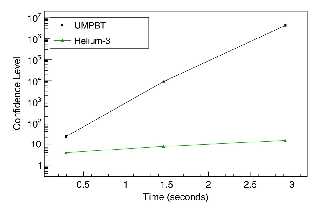
Fig.7 Confidence levels γ (i.e., γ=106 corresponds to a confidence level of 1 in 106) calculated for a 3He detector (triangles and green online) and the proposed detector (squares and black) using the UMPBT model.The confidence levels were derived from sets of 50 MCNP simulations with and without a source present.The confidence levels show a sensitivity comparison of the proposed detector to a standard 3He detector
5.2 Active interrogation technique with the proposed detector
Since the proposed detector uses fast neutrons to detect the presence of fissile material,it becomes possible to use a beam of low-energy neutrons for active interrogation.It is one of the key advantages of the proposed detector system.In particular,it is shown in Ref.[9] that 60 keV neutrons produced by7Li(p,n)7Be neutron generator can be utilized for this purpose.For the case of235U,the UMPBT model can be used to estimate the minimum time required to detect a fissile material under active interrogation.Plotting the two calculated values (Eqs.(3) and (6)) against one another provides a sensitivity limitation trend for our detector (Fig.8).Table 2 shows the minimum time it would take to detect various source strengths at various distances.

Fig.8 Detection time vs source-neutron intensity entering the detector.The plot is in logarithmic scale.The confidence level used is γ=106
The source intensity was converted into mass to determine how much of the material must be present in order to be detectable.We assume that neutron flux for a 60 keV beam isφ=5×106cm-2s-1,as in Ref.[9].The fission cross section,σ≈2 barns [28] at 60 keV,and the prompt neutron multiplicity,νp=2·42[28],of the235U+n reaction were used.Using equation (10),Avagadro’s number,NA,and the massM235U=235 g,the conversion was performed to estimate the mass for a range of source neutron intensities(Table 3).A similar plot to Fig.8 was then made with respect to mass (Fig.9).


Fig.9 Similar to Fig.8,but in terms of mass of 235U instead of source-neutron intensity.The confidence level used is γ=106
It is clear that the proposed detector system becomes extremely sensitive to even very small amounts of fissile material under active interrogation.Figures 8 and 9 indicate that 1 g of235U can be detected in less than a minute if modest flux of 5×106cm-2s-1of 60 keV neutrons is used for active interrogation.Note that it is not possible to use systems based on thermal neutron detection in this case because of the background which will be unavoidably caused by the interrogating neutron beam.
6 Summary and conclusion
Special nuclear materials should be carefully monitored and controlled.The monitoring of these materials is of critical importance for global security,especially weaponsgrade plutonium and highly enriched uranium.Detection of these materials can be facilitated by active interrogation with low-energy (<100 keV) neutrons.Even without active interrogation,our proposed detector design and analysis method overcomes the limitations set by thermalneutron detectors as well as the higher false alarm rate ofγray detectors.
Using MCNP6 simulations and the uniformly most powerful Bayesian tests statistical model,the limits of the proposed detector were probed.For a fissile material undergoing fission one meter away from the detector,without any moderation,it would take about 25 min to identify a source emitting ≈500 n/s,and similarly 192 seconds for ≈5000 n/s.For the specific case for235U+n,with the specific parameters discussed in Sect.5.2,these limits translate to 8.1 mg and 80.7 mg of235U,respectively.
Comparisons to commercially available neutron detectors,studied in Kouzes et al.[27],were made(Table 1).The requirements set by the National Committee on Radiation Instrumentation at the time of the previous study required a minimum neutron detection efficiency of 2.5 cps/ng.The detector proposed in the current work surpasses that requirements set.The proposed detector performs with an efficiency of 26.8 cps/ng.With the UMPBT model,a comparison of confidence levels for a particular source at various exposure times revealed a significant increase in sensitivity compared to the3He detector (Fig.7).With respect to the previously studied detectors described in Kouzeset al.,the proposed neutron detection has a significant advantage in efficiency and sensitivity.
Our method can be applied to the development of a monitoring device and the times produced scale linearly with the solid angle of the detector with respect to the source.Increasing the number of the proposed detectors in various positions around the source will increase the sensitivity and reduce the required detection time of the detector significantly.
Authors’ contributionsAll authors contributed to the design of the detector and the methodology of the study.Simulations and analyses were performed by Eric Aboud with assistance by Sunghoon Ahn.The UMPBT model was provided by Valen E.Johnson.The first draft of their manuscript was written by Eric Aboud,and all authors provided feedback on drafts of the manuscript.All authors read and approved the final manuscript.
杂志排行

Nuclear Science and Techniques的其它文章
- Calibrating the linearity between grayscale and element content for X-ray KES imaging of alloys
- High RF power tests of the first 1.3 GHz fundamental power coupler prototypes for the SHINE project
- Studies of the radiation environment on the Mars surface using the Geant4 toolkit
- Evaluation of neutron beam characteristics for D-BNCT01 facility
- A novel 4D resolution imaging method for low and medium atomic number objects at the centimeter scale by coincidence detection technique of cosmic-ray muon and its secondary particles
- Improved formation density measurement using controllable D-D neutron source and its lithological correction for porosity prediction