Effect of megapore particles packing on dielectric barrier discharge, O3 generation and benzene degradation
2022-02-15KefengSHANG商克峰WudiCAO曹无敌WeiweiHUAN郇伟伟NanJIANG姜楠NaLU鲁娜andJieLI李杰
Kefeng SHANG (商克峰), Wudi CAO (曹无敌), Weiwei HUAN (郇伟伟),Nan JIANG (姜楠), Na LU (鲁娜) and Jie LI (李杰)
1 School of Electrical Engineering,Dalian University of Technology,Dalian 116024,People’s Republic of China
2 School of Environmental Science and Technology, Dalian University of Technology, Dalian 116024,People’s Republic of China
Abstract Recently, packed-bed discharge plasma technologies have been widely studied for treatment of volatile organic compounds(VOCs),due to the good performance in improving the degradation and mineralization of VOCs.In this paper, a coaxial cylindrical dielectric barrier discharge reactor packed with porous material of micron-sized pores was used for degradation of benzene,and the discharge characteristics and ozone generation characteristics were studied.When the discharge length was 12 cm and the filling length was 5 cm,the packed particles in the discharge area significantly increased the number of micro-discharges, and the current amplitude and density increased with the pore size of packed particles, but the discharge power and ozone concentration showed a trend of first increasing and then decreasing.The discharge power and ozone production reached the maximum when the size of pore former was 75 μm,correspondingly, the degradation efficiency of benzene was the highest.
Keywords: plasma, packed bed dielectric barrier discharge, micro-discharge, ozone generation,benzene degradation
1.Introduction
As an important component of air pollutants, volatile organic compounds (VOCs) are irritant, carcinogenic and toxic.VOCs may also become the precursors of photochemical smog, secondary aerosols and tropospheric ozone, seriously endangering human health and the natural environment [1].Recently, discharge plasma technologies have been received attentions to waste gas[2–6]and water treatment[7–11],due to mild reaction condition, simple operation, fast treatment and wide application range for pollutant degradation.Owing to its good performance in the treatment of organic waste gas,dielectric barrier discharge(DBD) is one of the most extensively used methods for VOCs treatment [12, 13], especially the packed-bed DBD reactor in which the materials of good catalytic activities were packed[4].When catalytic or noncatalytic materials are filled between the discharge electrodes, polarized charges accumulated on the surface of the dielectric particles will produce high electric field in the micro gap between particles, leading to strong microdischarges.Therefore, the packed bed discharge reactor is beneficial to produce reactive species including O3, O, e, etc for degradation of VOCs.However, because microporous and mesoporous materials are usually used in plasma catalytic systems for supporting catalytic components such as Cu doped MnO2, Co–Mn, Ag/Au–CeO2, CeO2–MnOx[14–18], the deposition of intermediate products from the degradation of VOCs on the surface of the catalyst and the inside of pores easily causes the deactivation of catalyst and leads to low treatment efficiency of VOCs [17, 19, 20] because the reactive species is difficult to transfer into the pores of catalysts to react with the VOCs adsorbed in the pores [21].

Figure 1.Schematic of experimental system.
It was reported that micro-discharges can be generated in pores with micrometer size [22–25], and some simulation studies also show that plasma can be generated in the pores of structured catalysts with a pore diameter greater than 10 μm[26–28].Therefore, in this work micron-sized porous particles were packed in the discharge reactor for treating VOCs,which will be beneficial to reduce the deactivation probability of catalyst via a simultaneous production of micro-discharges between the packed particles and in their pores.This work mainly focused on the discharge characteristics of porous material with pores of tens of micrometer, and the effect of pore size on the production of O3and the degradation of VOCs was also tested.The future study will examine the VOCs degradation characteristics when porous particles support catalytic active components.
2.Experimental part
2.1.Material preparation
2.2.Experiment setup and methods
As shown in figure 1,the system mainly includes device packedbed reactor, an AC high-voltage power supply, measuring instruments for electrical parameters, ozone and benzene, a VOCs waste gas preparing system,which consists of a nitrogen cylinder, an air pump, mass flow controllers, benzene solution and a gas mixing bottle,etc.Air was used as the feeding gas to configure a specific concentration of benzene gas.
The discharge reactor with DBD configuration was shown in figure 2.The insulating medium is a quartz glass tube with an outer diameter of 15 mm, an inner diameter of 12 mm, a wall thickness of 1.5 mm, and a length of 350 mm; the high-voltage electrode is a stainless steel threaded rod with a diameter of 8 mm and a length of 430 mm.There is a 2 mm gas between the highvoltage electrode and the quartz glass tube into which the porous particles are packed.The low-voltage electrode is a stainless steel mesh close to the outer wall of the quartz glass tube.In order to decrease appropriately the air resistance and energy consumption,the different porous particles with a fixed volume were partially filled in the middle of quartz glass dielectric tube, and quartz cotton was used to fix the porous particles.In experiments, the initial concentration of benzene was 100 ppm, and the gas flow rate was 0.1 l min−1, which corresponded to a space velocity of 9550 h−1.The experiments were all carried out at room temperature and normal atmospheric pressure.
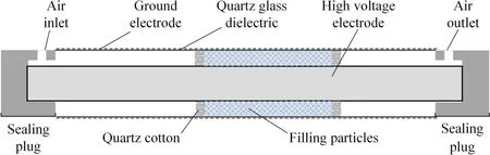
Figure 2.Schematic diagram of discharge device structure.
The high-voltage electrode was powered by an AC(0–60 kV, 50 Hz) power supply, and the applied voltage was measured by a voltage probe (Tektronix P6015A).A voltage probe(Tektronix TPPO200)measures the voltage signal across a sampling resistor(100 Ω)to obtain the discharge current,and a digital oscilloscope(Tektronix TDS2024)was used to record the voltage and current signals.The discharge power was calculated by the Lissajous figures, and charge was measured through monitoring the voltage signal across the sampling capacitor (1 μF) with a voltage probe (Tektronix P2220).The equivalent total capacitance Ccelland dielectric capacitance Cdcan also be calculated by the Lissajous figure.The ozone mass concentration was tested with an ozone monitor(Model 106M)and the concentration of benzene in the simulated exhaust gas was detected by a gas chromatograph (Shimadzu GC-2010).CO2/COxconcentration was detected by a gas chromatogragh(Techcomp GC7900).The organic by products were measured by GC-MS (GCMS-QP2020 Shimadzu).The degradation efficiency of benzene(η)and the production selectivity of CO2and COxwere calculated by equations (1)–(3).

2.3.Electric field simulation
In order to analyze the electric discharge in pores of packing particles, the AC/DC electrostatic module in the COMSOL Multiphysics engineering simulation software is used to establish a three-dimensional model for the micro-pore discharge (figure 3).The material of the high voltage electrode and the dielectric layer is set to stainless steel and aluminum oxide with a relative dielectric constant of 9.0, respectively,and the air gap is an air atmosphere of standard atmospheric pressure.Then, Gauss’s theorem (equation (4)) and electrostatic field loop theorem (equation (5)) were used for numerical calculation of the electrostatic field of pores in porous particles under the atmospheric air atmosphere, and the Poisson equation (equation (6)) and Laplace equation(equation (7)) were used to determine the unique boundary conditions.

Figure 3.Electrostatic field simulation model.(a) yz plane view (b)xy plane view.

where E is the electric field strength, ρ is the space charge density,0εis the dielectric constant in vacuum,2∇ is the Laplace operator,φis the electric potential, andεis the dielectric constant of the homogeneous medium.
3.Results and discussion
3.1.Material characterization

Figure 4.SEM image of sintered porous material sample.(a) Sintered sample without pore forming agent, (b) sintered sample with 25 μm pore forming agent, (c) sintered sample with 75 μm pore forming agent, (d) sintered sample with 150 μm pore forming agent.
A field emission scanning electron microscope (Nova Nano SEM 450)was used to observe and analyze the microstructure of the non-porous/porous material sample.As shown in figure 4, there were no voids in the sintered sample without pore former, but the sintered sample with pore former produced voids of different pore sizes which corresponded to the different particle sizes of pore former, namely, larger pore former corresponded to larger pore.
3.2.Effect of pore size of porous particles on discharge characteristics
The effect of pore size of porous particles on the discharge characteristics including the onset discharge voltage, the current pulse and charges was examined.The effect of pore former size of packed particles on the onset discharge voltage of packed-bed reactor is shown in figure 5.It can be seen that the packing of porous and non-porous particles apparently reduced the onset discharge voltage, and the onset discharge voltages of discharge reactor decreased with the increase in the pore size.For example, the onset discharge voltages of discharge reactor in air,packed with non-porous particles and porous particles prepared with pore formers of different diameters were 7.6 kV (no packed particles), 6.4 kV (nonporous particles), 4.8 kV (25 μm pore former), 4.4 kV (75 μm pore former), 4.0 kV (150 μm pore former), respectively.Hensel et al have also found similar phenomenon when studying the discharge characteristics of porous particles [22].According to Paschen law, the onset discharge voltage is dependent on the Pd value in which P is the gas pressure and d is the discharge gap, and the minimum onset discharge voltage appears at d = 186 μm.Therefore, the onset discharge voltage of packed-bed reactor will be decreasing with the increase in pore former diameter when the pore diameter is lower than 186 μm.
So the Princess and the baby floated and drifted in the chest on the sea all day and night, but the baby was not afraid of the waves nor of the wind, for he did not know that they could hurt him, and he slept quite soundly

Figure 5.Discharge onset voltage under different filling conditions.(The discharge length: 12 cm, the packed length: 5 cm, the packed particle size: 0.6–0.8 mm, and the dry air flow rate: 0.1 l min−1.)

Figure 6.Voltage and current waveform under different filling conditions.
Figure 6 shows the effect of pore former size on the voltage and current waveforms of packed-bed reactor.The current pulses when discharge chamber was packed by different porous particles were lower than air discharge (discharge chamber was not packed by porous particles) at the same applied voltage.A few works have reported that the equivalent capacitance of packing catalyst microgaps can store a small amount of charge,which forms a reverse electric field to restrain the discharge to develop into an arc discharge[25].Therefore, the self-limiting microdischarges in micropores of packing particles lead to less current pulses.However,compared to the electric discharge of packed-bed reactor which filled with non-porous particle, the number of current pulses produced by packed-bed reactor which filled with porous particles increased.The pores size determined the diameter of the discharge channels.The pores’ diameter is bigger, the channels of bigger diameter can develop inside pores of packed particles.At a given voltage, the larger channel can carry more discharge current pulses of higher amplitudes[19],leading to the increase in the current pulse in porous particles with large pores.
The electric field distributions in pores are simulated to understand the electric discharge characteristics in pores.Figure 7 shows that high electric field area develops into the hole with an increase in the pore diameter and the highest electric
field intensity reaches 3 × 10⁶V m−1which is enough for air breaking down.The strong electric field in the pore will greatly increase the probability of collision ionization and increase the electron density, and micro-discharge will occur in the pores when the electron density makes the Debye length smaller than the pore size.Zhang et al[26]also reported that the electric field inside the pore is higher than that in other spaces.The enhanced electric field inside the pore (1 × 10⁶V m−1) leads to the highest electron temperature in the hole(up to 6.3 eV),and then the ionization is enhanced, reaching a high ion density of 8.4 × 10¹⁷m−3.Zhang et al also found that the number of plasma migrated into the pore is one order of magnitude lower than that produced by direct ionization in the pore,and the high electric field strength in the pore promotes the production of micro-discharges in the pore with an aperture larger than 10 μm.These simulation studies proved the possibility of plasma generation in micro-sized pores.
Figure 8 shows the V–Q Lissajous figures of discharge reactor with/without packed particles.The packed particles caused the change of Lissajous figure from a parallelogram to an ellipse.The slopes of the left/right opposite sides and the upper/lower opposite sides of Lissajous figure correspond to the effective capacitances of discharge occurrence and extinguishment,respectively.Since the power supply charges the dielectric equivalent capacitance during the discharge phase,the effective capacitance corresponding to the discharge phase is the dielectric equivalent capacitance.However, the effective capacitance corresponding to the extinguishing phase is the total capacitance when the dielectric equivalent capacitance and the air gap equivalent capacitance are connected in series.The dielectric equivalent capacitance parameters calculated according to the V–Q Lissajous figure [29], were shown in figures 9 and 10.
Figure 9 examines the dielectric equivalent capacitance Cdunder different applied voltages in air discharge and in packedbed discharge reactor which filled non-porous and porous particles with pore former of 75 μm.Figure 9 indicates that the equivalent capacitance of the dielectric tends to increase with the applied voltage.Because the relative permittivity of dielectric(εd)and thickness (ld) remain unchanged, according to equation (8),Cdincreases with the effective discharge area (S).When the applied voltage is low, the discharge gap is partially broken down,which is an incomplete discharge state, and the dielectric capacitance value is small at this time.With the increase of the applied voltage, the air discharge becomes stronger and the number of filament channels increases accordingly, and the discharge filaments gradually diffuse throughout the discharge area,so the effective discharge area(S)on the surface of the dielectric increases, leading to a bigger dielectric capacitance

Figure 10 shows the dielectric equivalent capacitance under different filling conditions including no packing particles, packing nonporous particles, packing particles of pore former of 25, 75 and 150 μm.The applied voltage was 14 kV in this experiment.Figure 10 shows that the existence of filling nonporous/porous particles in the discharge area greatly improved the dielectric equivalent capacitance because the existence of filling particles increases the effective area of discharge via the production of micro-discharges in the pores of packing particles and between filling particles, therefore the bigger discharge area leads to the increase in dielectric equivalent capacitance according to equation (8).

Figure 7.Electric field distributions under different aperture sizes.(a) No pores, (b) 25 μm, (c) 75 μm, (d) 150 μm.

Figure 8.Lissajous figures under different filling conditions.
In addition, the peak-to-peak charge Qpk–pkand the discharge charge Qdin a single discharge cycle also can be obtained through the Lissajous pattern [30], as shown in figure 11.The results show that both the peak-to-peak charge and the discharge charge generated during the discharge process increased with the applied voltage.The enhancement on the electric field leads to the increase of the degree of ionization, thereby producing more charged particles.At the same time,the packed particles greatly increased the peak-topeak charge and the discharge charge, and they increased at first and then decreased with the increase in the size of pore former.The results show that packing nonporous and porous particles in the discharge region are conducive to effectively promote the charge transfer in the discharge process and the production of electric discharge.

Figure 9.Dielectric equivalent capacitance under different applied voltages.
The discharge power of reactor at different voltage was calculated according to Lissajous figure.Figure 12 shows that the discharge power was higher when nonporous and porous particles were packed in the reactor, and the power first increased with the diameter of pore former (<75 μm) and then decreased (150 μm).Air barrier discharge is a lowenergy discharge that diffuses from the dielectric surface to a larger surface discharge, but when porous/nonporous particles were packed in the discharge chamber, the microdischarges will be formed in the pores of particles of specific pore size and between packing particles of specific particle gap, the accumulation of more charges on the pore wall and particle surface increased the discharge power.However, the wall surface area of particles decreased with the pore diameter, so the surface of packing particles of larger pore size cannot be effectively charged[23],leading to lower discharge power.
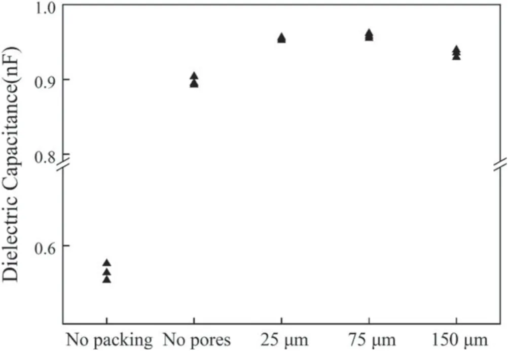
Figure 10.Dielectric equivalent capacitance under different filling conditions.
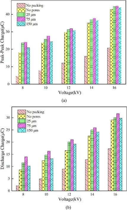
Figure 11.Charge characteristics under different filling conditions:(a) peak-to-peak charge, (b) discharge charge.
3.3.Ozone generation
Gas discharge will generate various active species such as O3,O, e, etc [11].In this paper, we measured O3for examining the effect of pore size on the discharge characteristics and the formation of active species.Figure 13 shows the generation of ozone under different filling conditions.The discharge length was 12 cm, the filling length of nonporous and porous particles was 5 cm,and the drying air flow rate was 0.1 l min−1.It can be seen that the ozone output increases significantly with the applied voltage, due to an increase in the electric field strength.Higher electric field intensity produced stronger electric discharge and therefore more electron collision reactions with oxygen molecules,thereby generating more ozone.At the same time,as the size of pore former increased from 0 to 75 μm,the ozone production tended to increase, but when the diameter of pore former increased to 150 μm, the ozone production decreased, which can be attributed to the weaker microdischarges.Moreover, the ozone production was consistent with the change trend of the discharge power, indicating that the packing particles of appropriate pore size has a better enhancement effect on electric discharge and the generation of active species.

Figure 12.Discharge power under different filling conditions.

Figure 13.Ozone concentration under different filling conditions.

Figure 14.Energy efficiency of ozone generation under different filling conditions.
The effect of filling conditions on the energy efficiency of ozone generation was shown in figure 14.When the applied voltage was increased from 14 to 16 kV, the energy efficiency decreased significantly; moreover, under the same voltage,the energy efficiency of ozone generation was higher when porous particles prepared by 75 μm pore former was packed in the discharge gap.For example, the energy efficiency of ozone generation at 14 kV when discharge gap was packed with porous particles prepared by 75 μm pore former was 20.21%, 7.20%, 7.19%, 5.06% higher than those when discharge gap was air, was packed with nonporous particles and packed with porous particles prepared by pore former of 25 or 150 μm respectively.Therefore, packing porous particles prepared by 75 μm pore former was advantageous for ozone generation.
3.4.Benzene degradation
Figures 15 and 16 show the effect of pore former size on the degradation rate and energy efficiency of benzene.It can be seen that the degradation rate of benzene increased with the applied voltage, but the energy efficiency of benzene degradation decreased with the applied voltage;moreover,packing with porous particles in the discharge gap increased the degradation rate and energy efficiency of benzene.When the excitation voltage was 16 kV, the degradation rates of benzene under the conditions of no filling,filling with nonporous particles, and filling with porous particles (75 μm pore former) were 42.67%, 43.60% and 50.41%, respectively.Stable microdischarges can be successfully generated in porous particles of a certain pore size and in the limited range of the I–V characteristic [22].The results show that when the pore size was 75 μm, stronger microdischarges were produced,which explains higher benzene degradation.As the pore size increased to 150 μm, the charge accumulation will decrease[23]; therefore, the microdischarges may not be stably developed, leading to the lower discharge power, ozone generation, and benzene degradation.Because packing nonporous and porous particles in the discharge gap increased the discharge power, the energy efficiency of benzene degradation was only slightly increased.However, packing porous particles in the discharge gap was still helpful for benzene degradation.

Figure 15.Benzene degradation rate under different filling conditions.

Figure 16.Energy efficiency of benzene degradation under different filling conditions.
Figure 17 shows the CO2and COxselectivity when the benzene was degraded in packed-bed reactor filing with porous particles prepared by 75 μm pore former.The CO2and COxselectivity increased with applied voltage.When the applied voltage was 16 kV, the CO2and COxselectivity were 78.08%and 87.98%, respectively, implying that most of benzene molecules were completely oxidized and only a small part was degraded into organic by-products.In order to identify the different degradation products, the gaseous by-products were measured by GC-MS.The by-products mainly included acids (Formic acid, Acetic acid and n-Hexadecanoic acid),ketones (Methyl Isobutyl Ketone, Acetylacetone, 2-Heptanone,2-Nonanone and 2,9-Decanedione), alkanes (3,4-Dimethylheptane and 2-Methyldecane) as well as aldehydes (Benzaldehyde,Nonanal and Dodecanal).The results in this work were similar to other reports [31, 32].
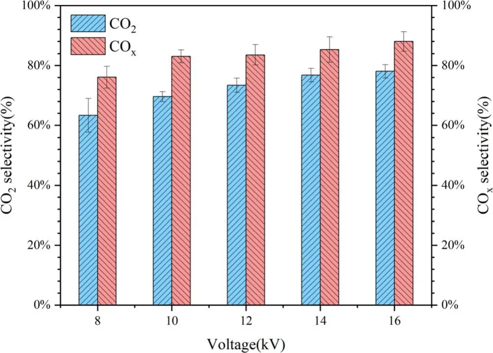
Figure 17.CO2 and COx selectivity of packed-bed DBD system filling with 75 μm porous particles.
4.Conclusions
Packing nonporous/porous particles in the discharge gap apparently changed the discharge characteristics of air discharge.When nonporous or porous particles were packed in the discharge gap, the current amplitude decreases significantly compared to air discharge, but the density of the current pulse increased, indicating that the presence of particles in the discharge zone promoted the formation of micro-discharges.
With the increase of the pore former size for preparing the packed particles, the discharge charge, discharge power,ozone generation and benzene degradation first increased to the maximum (75 μm pore former size) and then decreased.The enhancement of porous particles on the discharge charge and power is attributed to the generation of more mcirodischarges in the pores of packing particles and the gap of packing particles,which also results in the production of more ozone and higher benzene degradation.At an applied voltage of 16 kV, the CO2and COxselectivity reached 78.08% and 87.98%, respectively, and the main intermediates included formic acid, acetic acid, n-Hexadecanoic acid, methyl isobutyl ketone, acetylacetone, 2-Heptanone, 2-Nonanone, 2,9-Decanedione, 3,4-dimethylheptane, 2-methyldecane, benzaldehyde, nonanal and dodecanal.
Acknowledgments
This work is supported by National Natural Science Foundation of China (Nos.51977024, 21577011).
ORCID iDs
猜你喜欢
杂志排行

Plasma Science and Technology的其它文章
- Design of improved compact decoupler based on adjustable capacitor for EASTICRF antenna
- W fuzz layers: very high resistance to sputtering under fusion-relevant He+irradiations
- Discharge and post-explosion behaviors of electrical explosion of conductors from a single wire to planar wire array
- Influence of anode temperature on ignition performance of the IRIT4-2D iodine-fueled radio frequency ion thruster
- Experimental study on plasma actuation characteristics of nanosecond pulsed dielectric barrier discharge
- A novel double dielectric barrier discharge reactor with high field emission and secondary electron emission for toluene abatement