Zero-Sequence Current Suppression Strategy for Open-End Winding Permanent Magnet Synchronous Motor Based on Model Predictive Control
2020-10-27LIUHuashan刘华山LIJie李杰YAOFei姚飞
LIUHuashan(刘华山)1,2,LIJie(李杰)1,YAOFei(姚飞)1,2*
1 College of Information Science and Technology, Donghua University, Shanghai 201620, China2 Engineering Research Center of Digitized Textile & Apparel Technology, Ministry of Education, Shanghai 201620, China
Abstract: Compared with the traditional three-phase star connection winding, the open-end winding permanent magnet synchronous motor (OW-PMSM) system with a common direct current(DC) bus has a zero-sequence circuit, which makes the common-mode voltage and the back electromotive force (EMF) harmonic generated by the inverters produce the zero-sequence current in the zero-sequence circuit, and the zero-sequence current has great influence on the operation efficiency and stability of the motor control system. A zero-sequence current suppression strategy is presented based on model predictive current control for OW-PMSM. Through the mathematical model of OW-PMSM to establish the predictive model and the zero-sequence circuit model, the common-mode voltage under different voltage vector combinations is fully considered during vector selection and action time calculation. Then zero-sequence loop constraints are established, so as to suppress the zero-sequence current. In the end, the control strategy proposed in this paper is verified by simulation experiments.
Key words: open-end winding permanent magnet synchronous motor (OW-PMSM); zero-sequence current; harmonic; model predictive current control; common-mode voltage
Introduction
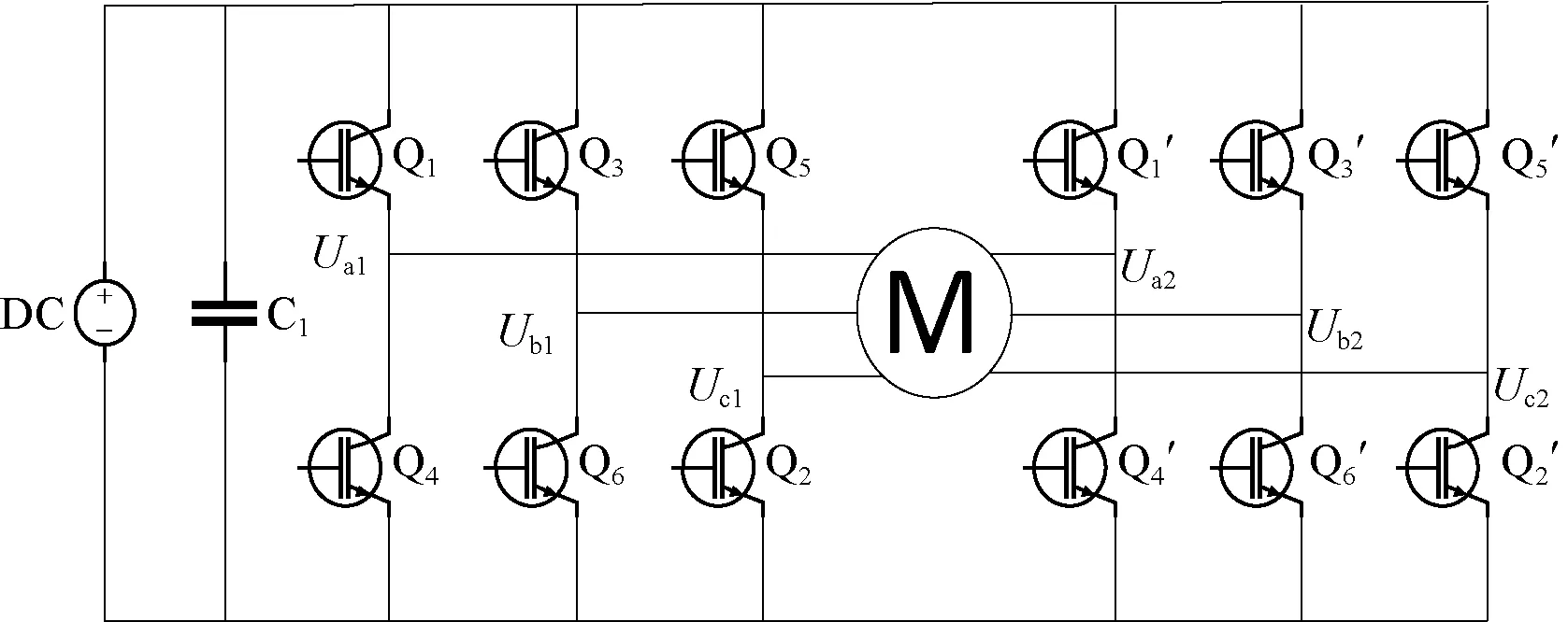
A permanent magnet synchronous motor (PMSM) has the advantages of high power density, flexible control and reliable operation, which is widely used in electric power related fields, such as electric vehicle and aerospace[1]. The open-end winding PMSM (OW-PMSM) means that the neutral point of the traditional three-phase star connection winding is opened, and adopts two inverters on both ends of winding. According to the direct current(DC) bus connection style, the OW-PMSM system can be divided into common DC bus topology and isolated DC bus topology[2-3], as shown in Fig. 1. Compared with the PMSM with star connection winding, the PMSM with open-end winding can provide higher power and effectively improve the utilization ratio of a DC bus[4].
In recent years, scholars in Zhejiang University and Harbin Institute of Technology continue to study the topology structures and the control strategy of the OW-PMSM. Most of the control strategies for the OW-PMSM are the migration and the improvement of traditional PMSM control strategies, such as direct torque control (DTC)[5-6]and field-oriented control (FOC)[7-8]. As a new control strategy, model predictive control (MPC) was gradually applied in the field of power electronic control. Compared with DTC and FOC, MPC is simple in calculation and parameter configuration, and fast in dynamic response[9]. MPC is divided into finite control sets-MPC (FCS-MPC) and continuous control sets-MPC (CCS-MPC)[10-15]. The FCS-MPC does not need a modulator and is widely used because of fully using the limited number of space voltage vectors.
(a) Common DC bus topology
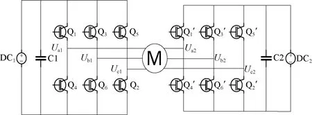
(b) Isolated DC bus topology
The system of OW-PMSM with a common DC bus has no neutral points because two buses are connected in parallel. So the system has a zero-sequence loop, and the zero-sequence current is generated under the action of common-mode voltage and the back electromotive force(EMF) harmonic. The presence of the zero-sequence current leads to additional energy loss and heating, and the zero-sequence current will cause torque ripple, which adversely affects the system operating efficiency and stability[16]. Therefore, suppressing the zero-sequence current in OW-PMSM system is one of the important research contents. In order to suppress the zero-sequence current, Somasekharetal.[17-18]used the strategy with an additional auxiliary switch to eliminate the common-mode voltage to inhibit the action of the zero-sequence current. But it is more complicated when the additional auxiliary switch is adopted, and it is adverse to the flexibility and stability of the control system. In Ref. [19], during the process of space vector modulation, only the voltage vectors which do not generate common-mode voltage are selected, so as to suppress the effect of the zero-sequence current. However, there is a serious shortage of DC bus voltage utilization. Nianetal.[20]designed zero-sequence current closed-loop regulation. The proportional resonant (PR) regulator is used to compensate the common-mode voltage on the resistance inductance, so as to achieve the purpose of suppressing the zero-sequence current by compensating the common-mode voltage and the back EMF harmonic. But this closed loop control strategy of the zero-sequence loop is complex in designing, difficult in parameter configuration, large in computation and so on.
In order to suppress the zero-sequence current in the common DC bus OW-PMSM system, this article analyzes the zero-sequence circuit through building a mathematical model of the OW-PMSM, and designs an improved model predictive current control strategy with fully using the advantages of multi-objective constraints of MPC. Then, the zero-sequence current can be suppressed by controlling zero-sequence voltage and back EMF harmonic reasonably. At last, the simulation experiments are done to prove the effectiveness of the proposed control algorithm.
1 Mathematical Model of OW-PMSM with Common DC Bus
In order to analyze the topological characteristics of the OW-PMSM system and suppress the zero-sequence current, it is necessary to establish a mathematical model containing zero-sequence components of the OW-PMSM system. Figure 1(a) shows the topology structure of the OW-PMSM system with a common DC bus. Under the assumption that the motor winding and the magnetic circuit are symmetric, and hysteresis loss and eddy current loss are ignored, the mathematical model of the OW-PMSM system in the three-phase static coordinate system can be obtained as
(1)
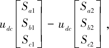
where,umandim(m=a,b,c) are phase voltages and phase currents ofa,bandcphases, respectively;Ris the winding resistance;LandMrepresent the self-inductance and mutual inductance of winding, respectively;Sx(x=a1,a2,b1,b2,c1,c2) represents the switching function of the inverter 1 and the inverter 2, and satisfies:
(2)
Generally, the mathematical model of PMSM in the three-phase static coordinate system is complicated for our control system design. In order to simplify the control system design and make our control more convenient and flexible, the mathematical model in the three-phase static coordinate system needs to be converted to the two-phase rotating coordinate system. Thus, the mathematical model of the OW-PMSM system can be obtained as
(3)
where,ux,ixandLx(x=d,q, 0) represent thed-axis,q-axis and 0-axis components of voltage, current and inductance in the rotating coordinate system, respectively;θrepresents the electric angle;ωrepresents the electric angular velocity;ψrepresents the flux chain.
According to Eq. (3), the equivalent circuit of the zero-sequence loop of the OW-PMSM system with the common DC bus can be obtained, as shown in Fig. 2. In Fig. 2,u01andu02are the common-mode voltages generated by the inverter 1 and the inverter 2, respectively; 3ωψ3fsin(3θ) is the harmonic amplitude of the third inverse EMF.
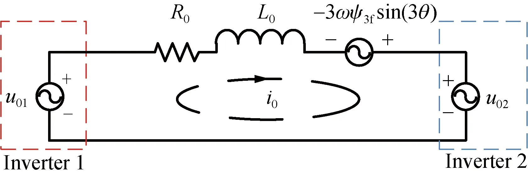
Fig. 2 Equivalent circuit of zero-sequence loop
As for the OW-PMSM system, due to the effect of the zero-sequence current, the electromagnetic torque will generate harmonic pulsation, and its torqueTecan be expressed as
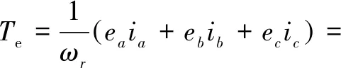
(4)
where,ea,ebandecrepresent three opposite electromotive forces in the three-phase static coordinate system;ed,eqande0representd-axis,q-axis and 0-axis components in thedq0 rotation coordinate system;ωrrepresents mechanical angular velocity;Cabc-dq0denotes theabc-dq0 coordinate transformation matrix.

Substituting Eq. (3) into Eq. (4), a simplified mathematical model can be obtained:
wherepnrepresents the pole log of the motor. It can be seen from Eq. (6) that the electromagnetic torque contains six harmonic components, which is not conducive to the stable operation of the system.
2 Zero-Sequence Current Suppression Based on MPC
2.1 Zero common-mode voltage suppression strategy based on MPC
Zero common-mode voltage model predictive current control (ZCV-MPCC) means that the resultant voltage vector does not contain zero-sequence components during the model predictive current control. The common-mode voltage at the machine end of the OW-PMSM system can be expressed as
u0=u01-u02.
(7)
That is, the zero-sequence component of the phase voltage of the motor depends on the zero-sequence component of the output voltage of the two inverters.
By analyzing the common-mode voltage generated when each voltage vector acts (shown in Table 1), it can be seen that the common-mode voltage is 0 when the vector vertex is located on the middle hexagon (HJLNQS) (shown in Fig. 3). In order to control the magnitude of the zero-sequence voltage component in a zero-sequence loop, only non-zero voltage vectors and zero vectors which do not generate common-mode voltage can be selected. The control block diagram is shown in Fig. 4, where PI means proportion integration regulator.

Fig. 3 Voltage vector of OW-PMSM
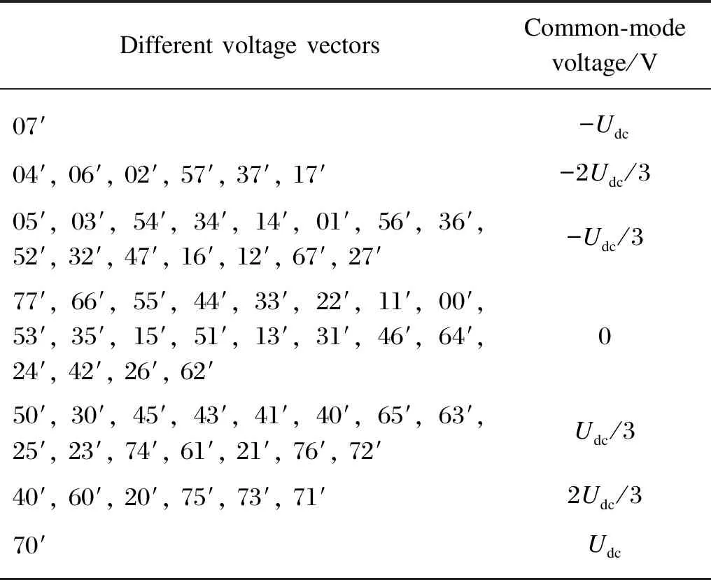
Table 1 Common-mode voltage generated by different voltage vectors
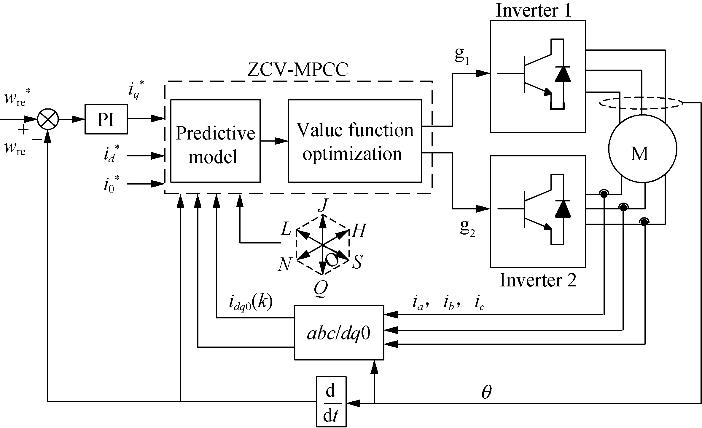
Fig. 4 Block diagram of ZCV-MPCC system for OW-PMSM
The mathematical model of OW-PMSM in thedq0 rotating coordinate system is discretized, and the predictive model can be obtained as
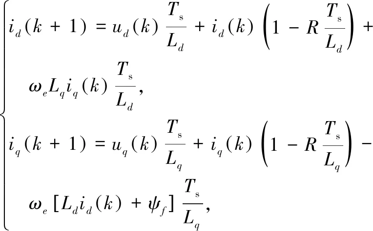
(8)
where,ix(k+1) andix(k)(x=d,q) represent thedq0-axis currents at the next moment and the current moment, respectively;ux(k+1) andux(k)(x=d,q) represent thedq-axis components under the action of different voltage vectors at the next moment and the current moment, respectively.
Then, the value function can be designed as
Ji=[id(k+1)-id(k)]2+[iq(k+1)-iq(k)]2,
(9)

Therefore, the value function can be approximated as

(10)
Different voltage vectors can get different value functionsJi.By comparing different value functions, the voltage vector that makes the value function minimum is obtained, and the voltage vector is applied to the next period of time, so that the predicted current can always track the given value of the current and achieve the purpose of fast and accurate control.
2.2 Expected common-mode voltage suppression strategy based on MPC
In the zero-sequence loop of the OW-PMSM system, the zero-sequence component is obvious not only the common-mode voltage output by the inverters, but also the back EMF harmonic generated by the motor, especially the third harmonic. In ZCV-MPCC, the influence of the common-mode voltage generated by the inverters on the zero-sequence current is considered. The control strategy is simple and flexible. The expected common-mode voltage model predictive current control(ECV-MPCC) takes the influence of the third harmonic of back EMF harmonics into account.
According to the OW-PMSM zero-sequence equivalent circuit, the magnitude of zero-sequence current depends on the common-mode voltage and the third harmonic of the back EMF generated by the inverters. Effectively reducing the circuit voltage of the zero-sequence circuit can reduce the zero-sequence current correspondingly. Therefore, the ECV-MPCC aims to select an appropriate voltage vector through model predictive control to make the expected common-mode voltage output of the inverters interact with the third harmonic of the back EMF, so as to reduce the zero-sequence loop voltage and suppress the zero-sequence current. The control system block diagram is shown in Fig. 5.
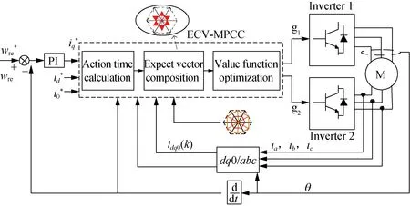
Fig. 5 Block diagram of ECV-MPCC system for OW-PMSM
According to the equivalent circuit of the zero-sequence circuit, if the circuit voltage of the zero-sequence circuit is zero, the zero-sequence current will not be generated. Therefore, the condition of the circuit voltage is zero:
u01-u02+3ωψ3fsin(3θ)=0.
(11)
Therefore, the zero-sequence loop voltage is zero, and the zero-sequence current generated is also zero when the magnitude of the common-mode voltage generated by the inverters is the same as the magnitude of the third harmonic of the back EMF. Obviously, it is necessary to select the appropriate voltage vector and the action time to synthesize the voltage vector, and generate the desired common-mode voltage vector to match the third harmonic of the back EMF.
The vector action time calculation adopts thedq0-axis current dead-beat tracking. That is, it is considered that the current values at the two consecutive sampling points are equal, which is equal to the given value of thedq0-axis current.
(12)
where,sdmandsqm(m=0,i,j) are thedq0-axis slopes ofu0,udanduq;sxi,sxjandsx0represent the slopes of the voltage vectors which are selected;ti,tjandt0are the acting time of voltage vectors, and the acting time satisfies:
Ts=ti+tj+t0.
(13)
Combined with the mathematical model of the OW-PMSM system in thedq0 rotating coordinate system, the slope can be calculated as
(14)
(15)
(16)
By substituting the formulas (14)-(16) into the dead-beat model, the acting time can be calculated as
(17)
(18)
t0=Ts-ti-tj.
(19)
The expected resultant voltage vectors in six sectors can be obtained by calculating and selecting the voltage vectors in six sectors and their acting time.
Vn=viti+vjtj+vztz,
(20)
whereVnrepresents the expected voltage vector synthesized in each sector,n=1, 2, …, 6.
The voltage component of synthetic voltage vectors atdq-axis can be calculated, and the predictive current at next sampling time can be obtained by bringing the voltage component of synthetic voltage vectors atdq-axis into the prediction model. Then, the value function is given to evaluate and select the optimal synthetic voltage vector. Therefore, the value function is redesigned by adding zero-sequence current constraint:
(21)

Since the vector action time is given in advance and evaluated in the value function, the corresponding optimal acting voltage vector and its action time can be obtained through the rolling optimization of the value function. At the same time, zero-sequence current weight is added in the value function evaluation process, and the constraint of zero-sequence current is fully considered, so that the obtained optimal voltage vector and its action time can well meet the requirements of zero-sequence current suppression.
3 Simulation
In order to validate the proposed zero-sequence current suppression strategy based on MPC, simulation experiments are carried out using the Matlab/Simulink platform. Under the control strategy proposed in this paper, the three-phase current waveform and the total harmonic distortion (THD), zero-sequence circuit current and common-mode voltage waveform, zero-sequence current and common-mode voltage comparison, and the electromagnetic torque waveform are obtained. The simulation results are shown in Figs. 6-9, respectively.
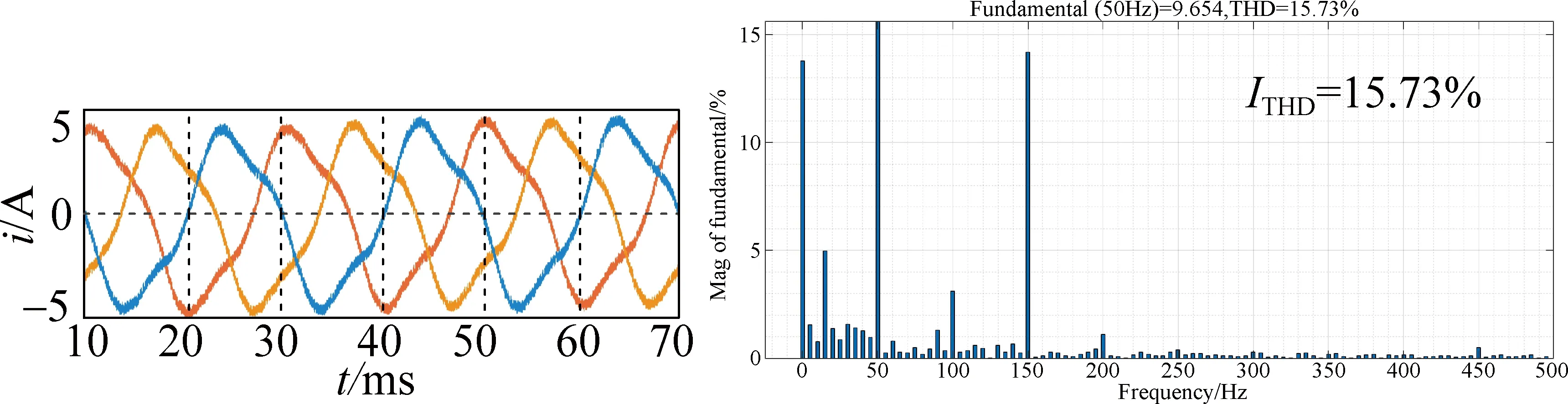
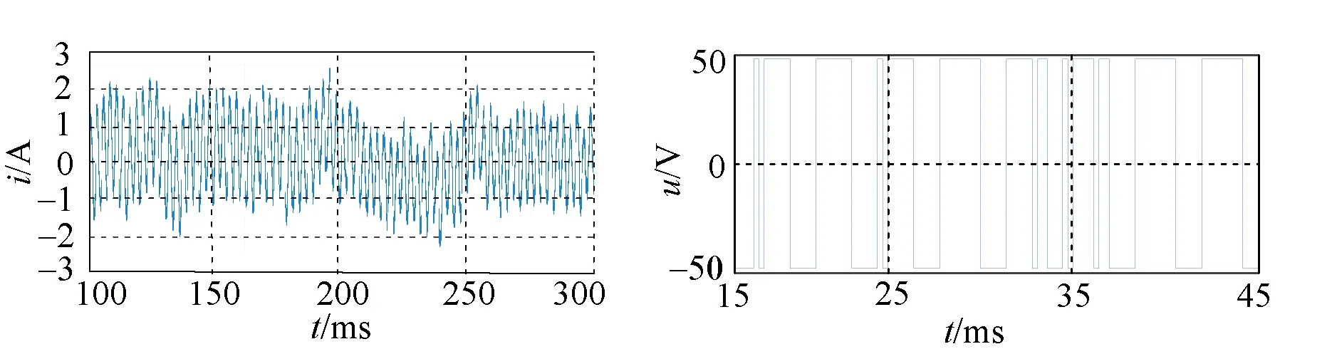
(a) Before zero-sequence current suppression
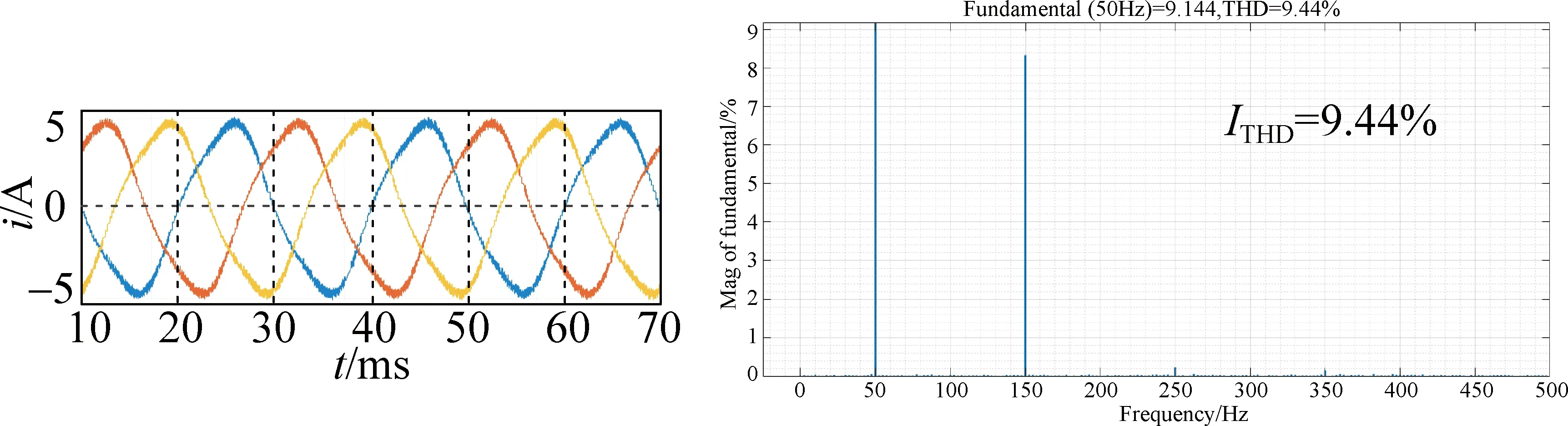
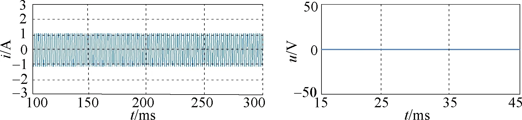
(b) ZCV-MPCC
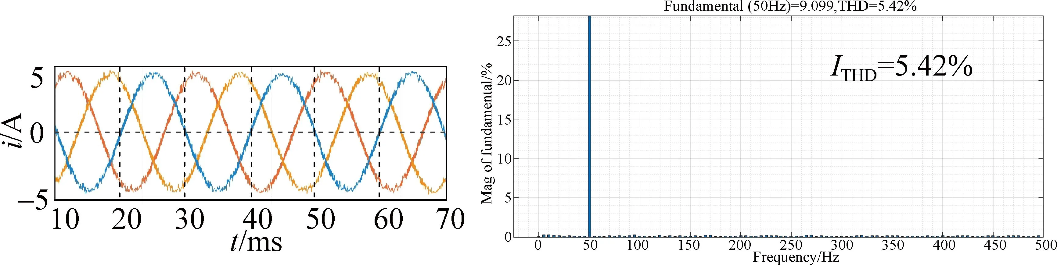
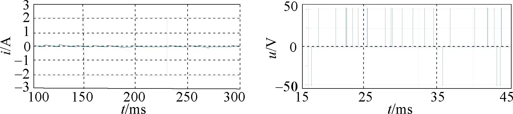
(c) ECV-MPCC
Figure 6 presents the three-phase output current waveform and the current THD (ITHD) under three different control strategies when the speed is 750 r/min. As can be seen from Fig. 6, the output current waveform can be improved to a certain extent, and the quality of current is improved when the ZCV-MPCC is used. The current distortion is significantly improved and THD is significantly reduced when using the ECV-MPCC, which fully proves the effectiveness of the ECV-MPCC.
Figure 7 presents the zero-sequence current waveform and common-mode voltage under three different control strategies when the speed is 750 r/min. In this paper the zero-sequence current under different voltage vectors and action times is measured as an index to measure the suppression strength of zero-sequence current. It can be seen from Fig. 7 that the current of the zero-sequence loop decreases obviously after the zero-sequence current control strategy is adopted, and the common-mode voltage is compatible with the control strategy adopted. The common-mode voltage of the OW-PMSM system using ZCV-MPCC is zero. The common-mode voltage using ECV-MPCC is adapted to the back EMF harmonic, and generates the certain common-mode voltage to interact with it in different sampling times, which plays a role in suppressing the zero-sequence current.
(a) Before zero-sequence current suppression
(b) ZCV-MPCC
(c) ECV-MPCC
Figure 8 presents the change trend of zero-sequence current amplitude and THD. It can be seen that the control of the zero-sequence current is more effective as the model predictive current control design deepens. The above trends fully demonstrate the effectiveness and the superiority of the new model predictive current control strategy.
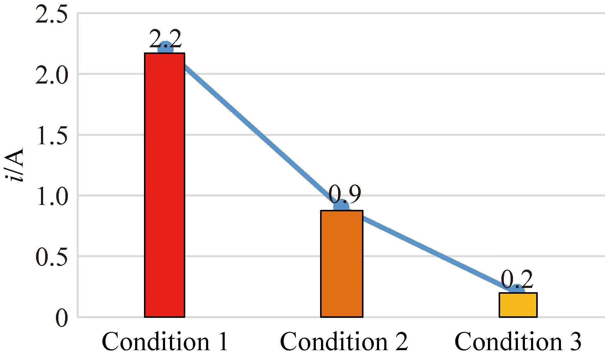
(a) Amplifude of zero-sequence current
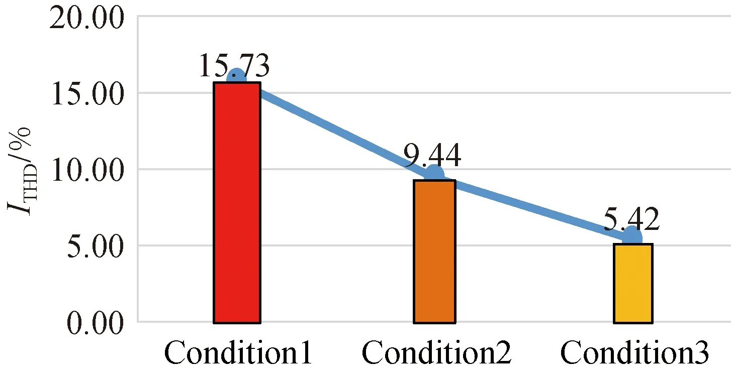
(b) THD of three-phase current
Figure 9 shows the torque waves of OW-PMSM in different working conditions, and the torque response changes when the load is suddenly added or reduced. By comparison, it can be seen that the torque ripple is obviously reduced after the adoption of the new control strategy, and the torque has a good response speed when the load changes, which fully demonstrates the effectiveness and good dynamic response of the control strategy proposed in this paper.

(a) Electromagnetic torque before zero-sequence current suppression
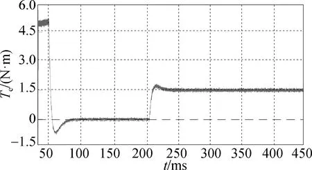
(b) Electromagnetic torque of ECV-MPCC
4 Conclusions
As a new topological structure, OW-PMSM can provide a higher utilization ratio of the DC bus, the three-phase current is independent, so the control is more flexible. Therefore, it has a good research and application prospect. In this paper, the problem of the zero-sequence current of the OW-PMSM system with a common DC bus was studied, and a new predict current control measurement was proposed. Compared with using the voltage vector that does not generate the common-mode voltage to suppress the zero-sequence current, the new model predictive current control algorithm can improve the utilization rate of the DC bus. The new model predictive current control can effectively suppress the generation of the zero-sequence current, reduce the torque ripple, and improve the operation stability of the OW-PMSM system. Compared with the traditional vector control used in the OW-PMSM system, the new model predictive current control has better dynamic response.
猜你喜欢
杂志排行

Journal of Donghua University(English Edition)的其它文章
- Emergency Evacuation Plan of the Louvre Based on Cellular Automata Superposition Model
- Undrained Stability Analysis of Three-Dimensional Rectangular Trapdoor in Clay
- Comprehensive Evaluation Method for Safety Performance of Automobile Textiles
- Method for Detecting Fluff Quality of Fabric Surface Based on Support Vector Machine
- Preserving Data Privacy in Speech Data Publishing
- Improved Fibroblast Adhesion and Proliferation by Controlling Multi-level Structure of Polycaprolactone Microfiber