Experimental study on plasma actuation characteristics of nanosecond pulsed dielectric barrier discharge
2022-02-15HaoZHENG郑浩HuaLIANG梁华JieCHEN陈杰HaohuaZONG宗豪华XiangzheMENG孟祥喆LikeXIE谢理科andYinghongLI李应红
Hao ZHENG (郑浩), Hua LIANG (梁华), Jie CHEN (陈杰),Haohua ZONG (宗豪华), Xiangzhe MENG (孟祥喆), Like XIE (谢理科) and Yinghong LI (李应红)
1 Science and Technology on Plasma Dynamics Laboratory, Air Force Engineering University, Xi’an 710038, People’s Republic of China
2 Chinese Flight Test Establishment, Xi’an 710089, People’s Republic of China
3 School of Mechanical Engineering,Xi’an Jiaotong University,Xi’an 710049,People’s Republic of China
Abstract Combining high-speed schlieren technology and infrared imaging technology, related research has been carried out on the influence of parameters such as actuation voltage, repetition frequency, and electrode size of an actuator on the discharge characteristics, induced flow field characteristics,and thermal characteristics of nanosecond pulsed dielectric barrier discharge.The results show that increasing the value of the actuation voltage can significantly increase the actuation intensity, and the plasma discharge area is significantly extended.Increasing the repetition frequency can increase the number of discharges per unit time.Both will cause more energy input and induce more changes in the flow field.The effect of temperature rise is more significant.The width of the covered electrode will affect the potential distribution during the discharge process, which in turn will affect the extension process of the plasma discharge filament.Under the same actuation intensity,the wider the covered electrode,the larger range the induced flow field and temperature rise is.Preliminary experimental analyses of high-frequency actuation characteristics,temperature field characteristics,flow field characteristics and actuation parameter settings provide support for the parameter selection and partial mechanism analysis of plasma anti-icing.
Keywords: NS-DBD, actuation voltage, repetition frequency, induced flow field,temperature rise
1.Introduction
Nowadays, the dielectric barrier discharge (DBD) based on sinusoidal alternating current high frequency and high voltage actuation (AC-DBD) and dielectric barrier discharge based on nanosecond pulsed voltage actuation (NS-DBD) are the most studied in the plasma application field[1–4].These two discharge methods are widely used in flow field control.The first to attract researchers is AC-DBD,which can induce a wall jet with a speed ranging from 0 to 11 m s−1,and it can control the flow separation of the flow field with an incoming flow velocity up to 100 m s−1[5–7].Later,studies have shown that NS-DBD has stronger flow control capabilities, so in recent years it has also attracted more and more attention from researchers.For NS-DBD, the flow control mechanism is mainly the rapid heat release effect caused by the rapid heating of local air [8–10].
During the study of the actuated discharge characteristics of NS-DBD plasma, the influence of the actuation parameters, the configuration of the actuator,the type of the insulating dielectric layer on the energy consumption, the voltage and current waveform, and the discharge modes are mostly discussed.Jiang Hui et al[11–14]studied the influence of actuation voltage peak, actuation frequency, electrode width, and electrode spacing on the discharge characteristics of NS-DBD.The results showed that increasing the actuation voltage could make the discharge filament more uniform, and meanwhile the plasma filament length would also increase.Zhou Yang et al [15]compared the discharge characteristics of nanosecond pulsed plasma actuation and microsecond pulsed plasma actuation at different actuation voltages.The results showed that with the actuation voltage amplitude increasing, the current peak value and energy consumption of the surface DBD at the two actuation conditions increase.Ndong et al [16] conducted experimental studies on the voltage and current waveforms and the changes of single pulsed energy at different electrical parameters.Compared with the negative polarity pulsed voltage, the positive polarity pulsed voltage actuation can bring greater energy deposition.Takashima et al [17] used high-speed schlieren technology to observe the flow field characteristics of the NS-DBD plasma actuation from the lateral and longitudinal sides of the actuator respectively and observed the shock wave structure.Zhao et al[18,19]used a dynamic pressure sensor with a higher response frequency and a two-dimensional phase-locked PIV to measure the flow field characteristics of NS-DBD actuation.The NSDBD plasma actuation can induce an instantaneous flow of the flow field, and a continuous vortex with a speed less than 0.3 m s−1will be generated near the wall area.The heat generated by NS-DBD plasma actuation can be divided into two parts:the rapid heating of the air near the wall and the heating of the dielectric layer material.At the same time,there is a process of convective heat transfer between the dielectric layer material and the heated air on the upper layer[20].Unfer et al[21]simulated and calculated that nanosecond pulsed plasma actuation would instantaneously (at the time scale of a nanosecond) heat the air near the wall to about 1000 K.The simulation results of Zhu Yifei et al [22, 23] showed that the near-wall air would be rapidly heated to 1100 K and then rapidly dropped to 310 K at a speed of k = −225/t Ks−1, and the heating area was approximately equal to the extension area of plasma discharge filaments.The simulation results of Zhu Yifei et al showed that the nearwall air would be rapidly heated to 1100 K and then rapidly dropped to 310 K at a speed of k = −225/t Ks−1and the heating area was approximately equal to the extension area of plasma discharge filaments.Popov et al [24] proposed a rapid heating model of breakdown discharge in the nitrogen–oxygen mixture environment.Under different reduced field intensities,the physical and chemical reactions that play a major role in gas heating are the dissociation reaction of oxygen caused by electron collision and the dissociation reaction of nitrogen molecules under the action of electron collision.
Researchers have studied the effects of peak actuation voltage, pulsed actuation frequency, and electrode size of the actuator on the discharge characteristics and induced flow field characteristics of NS-DBD.However, there are few researches on the infrared radiant thermal characteristics of NS-DBD.With the development of NS-DBD plasma actuation,it can not only be used for flow control,but also has application prospects in the field of aircraft anti-icing[25,26].Therefore, the law of its thermal effect and induced flow field effect with actuation parameters is worthy of in-depth research.
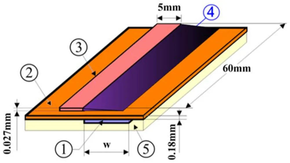
Figure 1.Surface dielectric barrier discharge plasma actuator.
In this work, the effects of the pulsed voltage, actuation frequency and the width of the covered electrode on the discharge characteristics, flow field characteristics and infrared radiation thermal characteristics of NS-DBD have been studied,and the influence of various parameters on the actuation characteristics of NS-DBD plasma has been obtained.
2.Experimental setup
2.1.Plasma actuator and power supply
The configuration of the plasma actuator is shown in figure 1,including an upper electrode,a covering electrode,an insulating medium (Kapton), and a base plate.Copper foil with a thickness of 0.027 mm is used as the electrode material of the actuator.The upper electrode is exposed in the air and the width is 5 mm.The width of the covering electrode w is selected as three sizes:5 mm,10 mm,and 20 mm respectively.The lengths of the upper electrode and the covering electrode are both 60 mm.The dielectric layer is made of polyimide tape with a thickness of 0.18 mm and a dielectric constant of 3.4.The substrate plate is an aluminum nitride ceramic sheet with an area of 100 mm × 100 mm and a thickness of 1 mm.
The nanosecond pulsed power supply (Parametric Highvoltage Pulsed Power Supply, Xi’an Smart Maple Electronic Technology Co.,Ltd,Xi’an,China)is used in the experiment.The output voltage waveform is shown in figure 2.The peak output voltage range of the power supply is continuously adjustable from 0 to 20 kV.The pulsed repetition frequency is continuously adjustable from 1 Hz to 20 kHz.the pulsed width tpis adjustable from 0 ns to 1 ms, and the rising edge time trand falling edge time tdare both adjustable.
2.2.Discharge characteristic test system
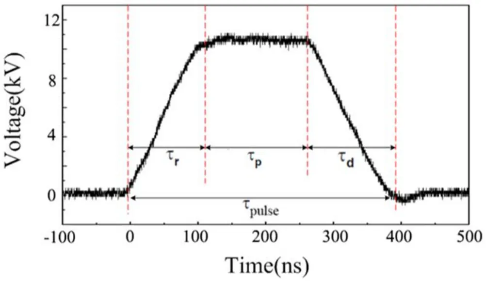
Figure 2.Schematic diagram of the output voltage waveform of the nanosecond pulsed power supply.
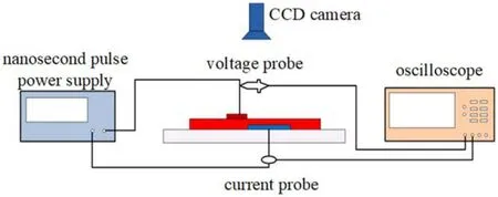
Figure 3.Layout of NS-DBD electrical characteristics test system.
The NS-DBD plasma actuation discharge characteristic test system mainly includes a voltage probe, a current probe, an oscilloscope, and a CCD camera, as shown in figure 3.The voltage and current applied to the upper electrode and the covering electrode of the actuator were measured by a voltage probe (Tektronix, P6015A) and a current probe (Tektronix,TCP0030A), respectively.The accuracy of the current probe is 1 mA.A digital oscilloscope(Tektronix,DPO4104)is used to display and store voltage–current signals at a sampling frequency of 5 GHz.The discharge image was taken by a Nikon D7000 digital camera with an exposure time of 0.04 s.The single pulsed energy of NS-DBD was computed by the integration of product the voltage and current acquired through oscilloscope over the single pulsed time: =W
2.3.Flow field characteristic test system
The high-speed schlieren technology is used to observe the induced flow field of NS-DBD plasma actuation in still air.As shown in figure 4,the high-speed schlieren test system mainly includes a xenon lamp, lens, knife edge, and high-speed camera.The xenon lamp is used as the light source to produce a parallel light path between the two concave lenses.The NSDBD plasma actuator is placed in the parallel light path to observe the NS-DBD plasma actuation induced flow field.A high-speed camera (Phantom—V2512) was used to capture the schlieren image induced by NS-DBD actuation.The camera frame rate is 40 000 fps.During the experiment, the resolution is 1024 × 1024 pixel2, and the camera exposure time is 0.000 002 s.The field of view for schlieren is 25 mm high and 30 mm long, and the actuator is perpendicular to it and parallel to the optical path.Through the DG535 timedelay pulsed generator,the high-voltage pulsed power supply,and the high-speed camera are triggered synchronously to shoot.

Figure 4.High-speed schlieren experimental system diagram.

Figure 5.Schematic diagram of positive and negative peak current and single pulsed energy change with voltage.
2.4.Infrared radiant heat characteristic test system
The infrared thermal imager used in the experiment is FLIR SC7300M, and the temperature measurement range is from−20 °C to 2000 °C.The infrared thermal imager is close to the surface of the actuator, so the attenuation of radiated power caused by the absorption and scattering of various components in the air can be ignored.The emissivity of polyimide tape was set as 0.83.The sampling frequency of the infrared thermal imager in the experiment is 25 Hz.
3.Experimental results and analyses
3.1.Influence of pulsed voltage peak
The pulsed actuation frequency of 2 kHz, rising edge time of 150 ns,a pulsed width of 100 ns,falling edge time of 150 ns,and covering electrode width of 20 mm were selected to remain unchanged, and the output voltage peak value was changed.

Figure 6.Discharge images of different voltage peaks (exposure time 0.04 s).
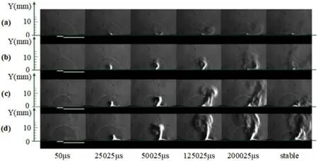
Figure 7.Variation process of the flow field induced by nanosecond pulsed actuation with different pulsed voltage peaks: (a) 8 kV, (b)10 kV, (c) 12 kV, (d) 14 kV.
Figure 5 shows the variation of single pulsed energy and the peak value of positive and negative current with the increase of the pulsed voltage peak value.It can be seen that with the increase of the peak value of the pulsed voltage, the peak value of the positive and negative pulsed current and the single pulsed energy both increase nonlinearly, which is consistent with the research results in the literature [27].
Figure 6 shows the discharge images at different voltage peaks.It can be seen that the voltage peak has a greater impact on the discharge area and discharge pattern.When the peak voltage is 8 kV, the discharge is mainly concentrated in the range less than 2 mm from the edge of the electrode, the discharge area is small, and the brightness is darker from the discharge image.With the increase of the voltage peak value,the discharge filaments continue to grow, the discharge area gradually increases, and the discharge becomes more intense and the brightness is greater.Therefore, a larger range of plasma discharge can be obtained by increasing the peak value of the pulsed voltage.
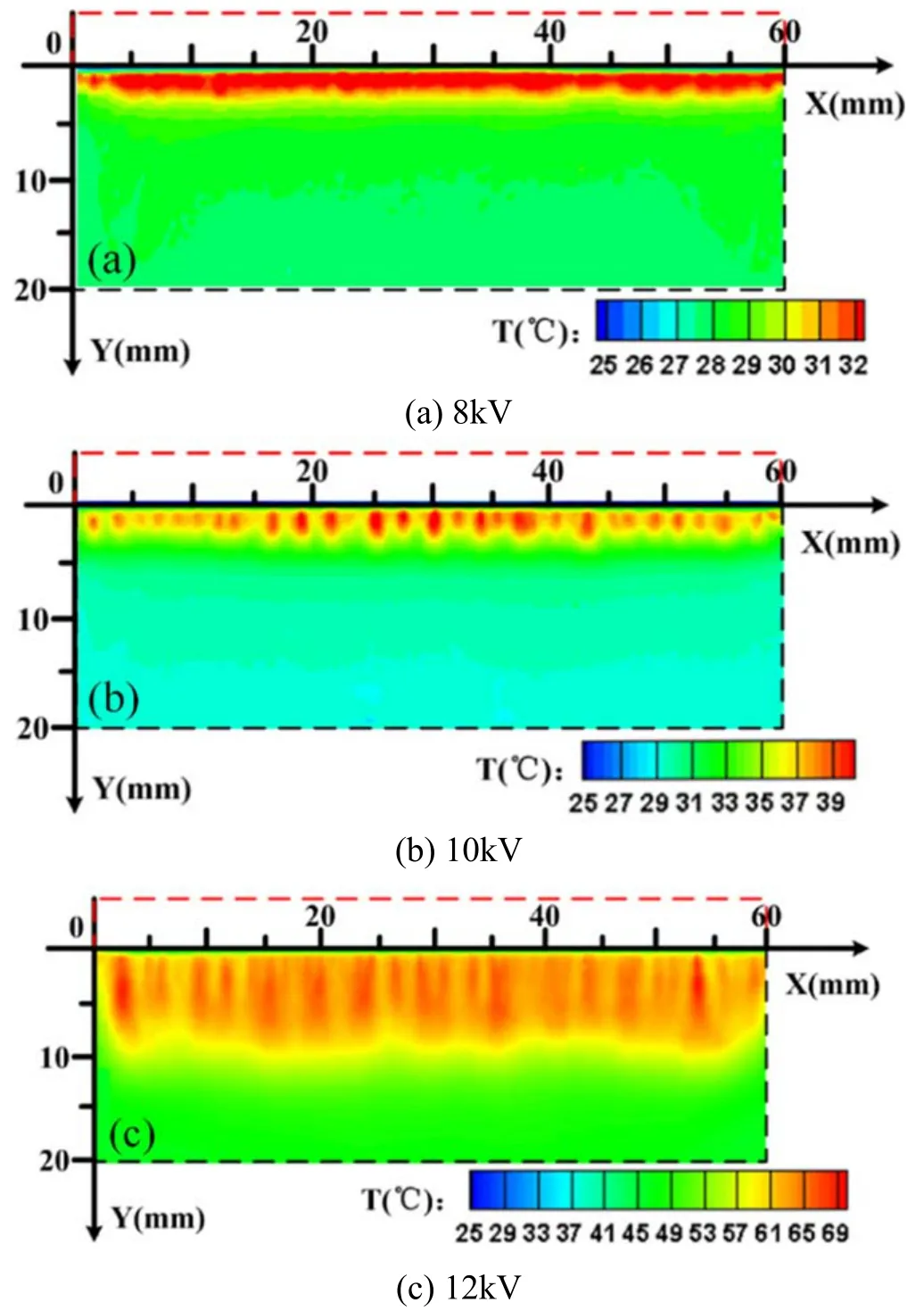
Figure 8.Surface temperature distribution of the actuator after continuous discharge of 120 s(t = 120 s)with different pulsed voltage peaks.
Figure 7 shows the change process of the flow field induced by nanosecond pulsed actuation with different pulsed voltage peaks.It can be seen that the greater the peak value of the pulsed voltage, the greater the actuation intensity and the greater the disturbance to the still air.In addition, it can be concluded that by observing the change in the length of the tail as the peak value of the pulsed voltage increases,the tail of the induced shock wave structure becomes longer.Combined with the discharge image, it can be obtained that the length of the tail of the shock wave structure is related to the length of the discharge filament, which is consistent with the previous conclusions.
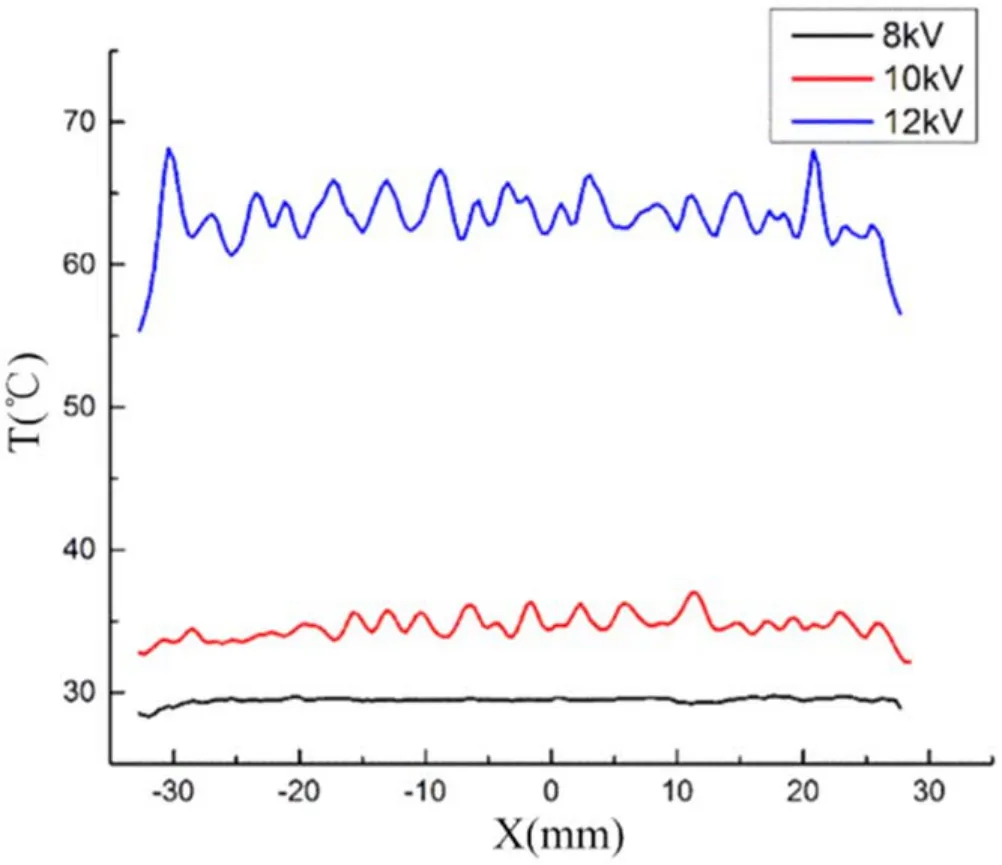
Figure 9.The surface temperature changes under different pulsed voltage peak values along the X-axis at Y = 4 mm direction(t = 120 s).
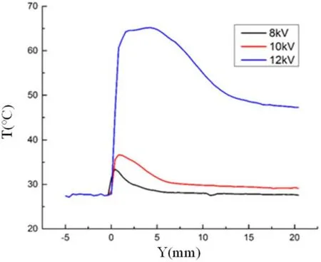
Figure 10.Changes of surface temperature along the Y-axis at X = 30 mm at different pulsed voltage peaks (t = 120 s).
Figure 8 shows the distribution of the surface temperature of the actuator with different pulsed voltage peaks at the time of 120 s.It can be seen that as the peak value of the pulsed voltage increases, the surface temperature of the dielectric layer will increase significantly,and the high-temperature area will also increase significantly.
Figure 9 shows the changes of the surface temperature along the X-axis at Y = 4 mm under different pulsed voltage peak conditions (t = 120 s).When the pulsed voltage peak value increases from 8 to 10 kV, the surface temperature increases by about 5 °C.When the peak value of the pulsed voltage increases from 10 to 12 kV,the temperature increases by nearly 30 °C.

Figure 11.Variation of surface temperature with time at point A(X = 30 mm, Y = 4 mm) at different pulsed voltage peaks.
The results in figures 10 and 11 also show that the surface temperature significantly increases with the increase of the pulsed voltage peak value.It can be seen from the graph of surface temperature changing with time in figure 11 that the higher the peak value of the pulsed voltage,the faster the surface temperature rises.Besides, it should be pointed out that in figure 11, when the pulsed voltage peak value is 14 kV, the sudden drop in temperature at the time of 72 s is caused by the breakdown of the actuator.The insulating medium (Kapton) near the upper electrode reaches the ignition point, causing the insulating material to ignite and breakdown.A plasma arc was generated at the location where it was pierced, and a strong current was formed, causing the circuit to short-circuit.
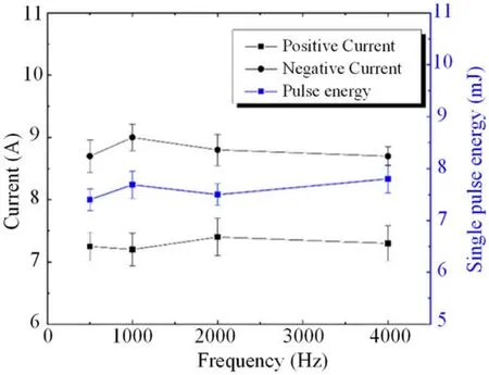
Figure 12.Schematic diagram of positive and negative peak current and single pulsed energy change with frequency.

Figure 13.Discharge images of different pulsed frequencies (exposure time 0.04 s).

Figure 14.Variation process of the flow field induced by nanosecond pulsed actuation with different pulsed actuation frequencies: (a)500 Hz, (b) 1000 Hz, (c) 2000 Hz, (d) 4000 Hz.
Increasing the pulsed voltage peak increases the actuation intensity of the single pulsed energy,so the input energy is also very high.The intensity of the electric field increases as the voltage increases, so that the gas far away from the upper electrode can also be broken down.Thus,the discharge filament becomes longer with the increase of voltage.The higher the energy is, the faster the surrounding flow field flows, the faster the temperature rises and the wider the actuation range is.
3.2.Influence of pulsed actuation frequency
The pulsed voltage peak value is 12 kV,the rising edge time is 150 ns, the pulsed width is 100 ns, the falling edge time is 150 ns,and the covering electrode width is 20 mm.Further study was carried out by changing the pulsed actuation frequency.
Figure 12 shows the variation of the single pulsed energy and the peak value of positive and negative current with the increase of pulsed actuation frequency.It can be seen that the change of the pulsed actuation frequency has almost no effect on the peak value of the positive and negative current and the single pulsed energy,indicating that the change of the pulsed actuation frequency only changes the number of discharges per unit time, but has no effect on the single discharge process.This conclusion is consistent with the conclusion in the literature[25],but is not consistent with the conclusion in the literature[17].The difference in experimental results is due to the different internal structures and design principles of the high-voltage pulsed power supply.
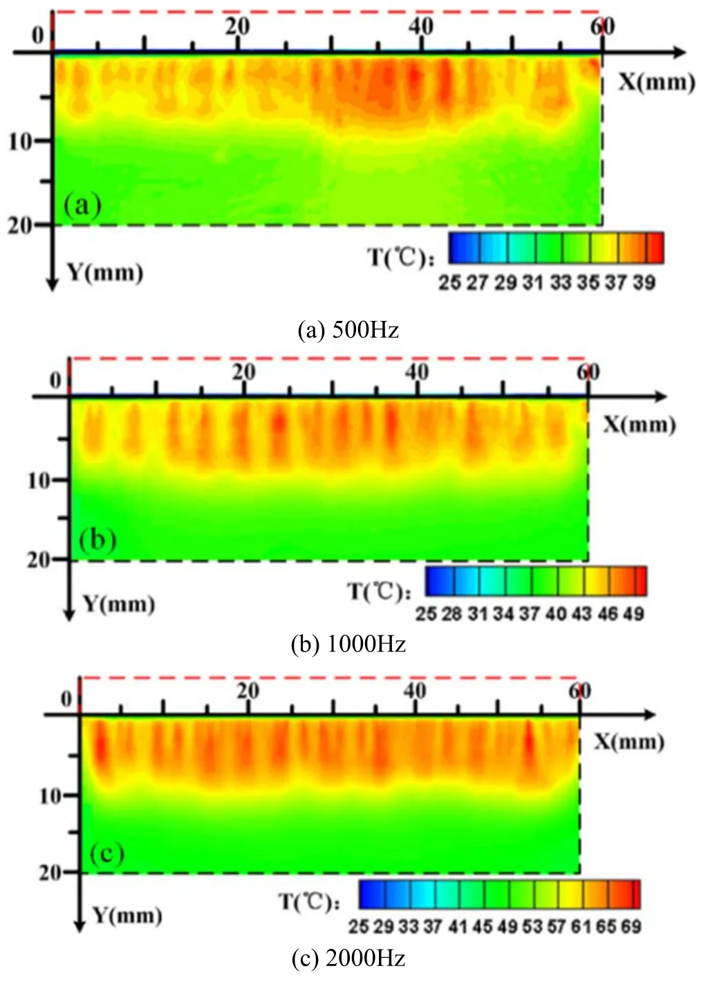
Figure 15.Surface temperature distribution of the actuator after continuous discharge of 120 s (t = 120 s) with different pulsed actuation frequencies.

Figure 16.The surface temperature changes under different pulsed actuation frequencies along the X-axis at Y = 4 mm direction(t = 120 s).
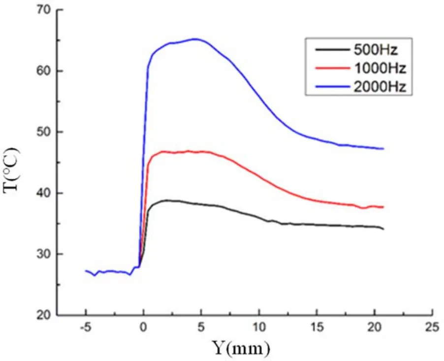
Figure 17.Changes of surface temperature along the Y-axis at X = 30 mm at different pulsed actuation frequencies (t = 120 s).
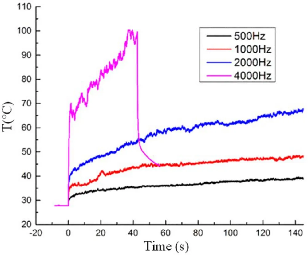
Figure 18.Variation of surface temperature with time at point A(X = 30 mm, Y = 4 mm) at different pulsed actuation frequencies.
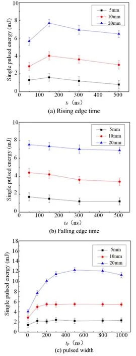
Figure 19.Variation of single pulsed energy with rising edge time,falling edge time,and pulsed width with different covered electrode widths.
Figure 13 shows the discharge images of different pulsed actuation frequencies.By comparison,as the pulsed frequency increases, the filament discharge brightness gradually increases, but the filament length and discharge area hardly change.The reason is that the actuation frequency does not affect the single discharge process.With the increase of frequency, the discharge times per unit time increase,which is reflected in the discharge images of multiple pulsed integrals,so the brightness increases.
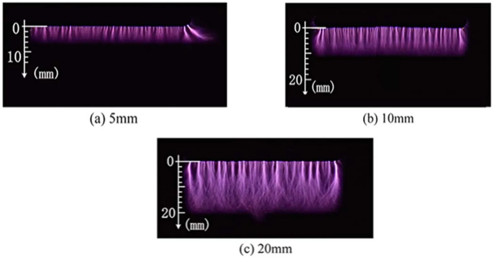
Figure 20.Discharge images with different covered electrode widths (exposure time 0.04 s).
Figure 14 shows the change process of the flow field induced by nanosecond pulsed actuation with different pulsed actuation frequencies.It can be seen from the figure that the single shock wave structure almost does not change with the increase of pulsed actuation frequency, which is consistent with the previous conclusion that changing the pulsed actuation frequency has almost no effect on a single discharge.Besides, as the pulsed actuation frequency increases,the more discharge times per unit time, the faster the energy accumulation,and the faster the induced flow field tends to a steady state.
Figure 15 shows the surface temperature distribution cloud diagram under different pulsed actuation frequencies after the discharge time is 120 s.Figures 16 and 17 show the temperature distribution along the X-axis and Y-axis, respectively.It can be seen that increasing the pulsed actuation frequency will keep the heated area unchanged, but the surface temperature of the dielectric layer will increase accordingly.Because the pulsed actuation frequency is increased,the number of discharges per unit time increases.However,the single pulsed energy remains unchanged, so the energy loaded per unit time increases and the surface temperature of the dielectric layer increases.According to the results given in figure 18, as the pulsed actuation frequency increases, the temperature rises faster.
The pulsed voltage peak remains unchanged to change the actuation frequency, but the single pulsed energy of the discharge does not change.The width of the discharge filaments is unchanged, but the brightness is brighter.This is because the increase of frequency makes the discharge filament that can be recorded increase,and the brightness is more obvious.Increasing the frequency increases the input power and the energy injected into the flow field, strengthening its effect on the surrounding flow field and increasing the thermal effect accordingly.
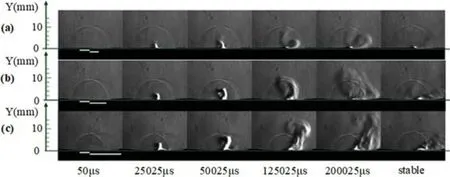
Figure 21.Variation process of the flow field induced by nanosecond pulsed actuation with different covered electrode widths: (a) 5 mm,(b) 10 mm, (c) 20 mm.
3.3.Influence of the covered electrode width
The peak value of the pulsed voltage is 12 kV, the pulsed excitation frequency is 2 kHz, and the width of the covered electrode is changed.
Figure 19 shows the variation of the single pulsed energy with the change of the rising edge time,falling edge time,and pulsed width with different coverage electrode widths.It can be seen that the width of the covered electrode has a greater influence on the single pulsed energy,and the wider the width of the covered electrode,the greater the single pulsed energy.Under different coverage electrode widths,the changing trend of single pulsed energy with a rising edge, falling edge, and pulsed width is not obvious.However, the smaller the electrode width, the smaller the influence of the electrical parameters on the single pulsed energy change.
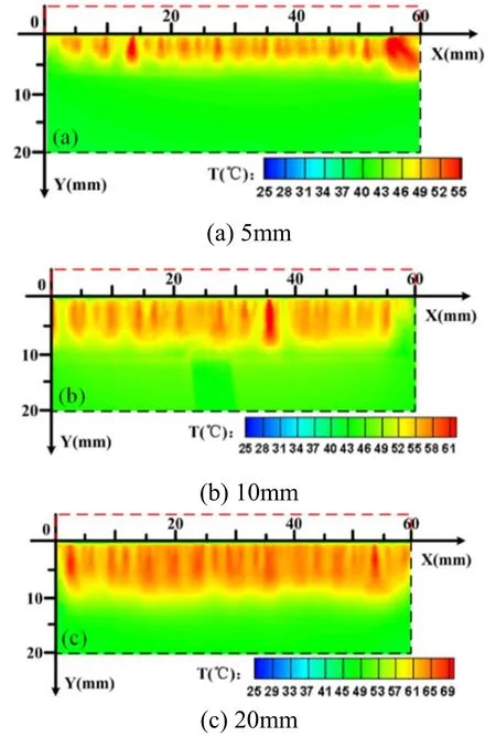
Figure 22.Surface temperature distribution of the actuator after continuous discharge of 120 s (t = 120 s) with different covered electrode widths.
Figure 20 shows the discharge images of different electrode widths when the pulsed voltage peak is 12 kV, the pulsed frequency is 2 kHz, the rising edge time is 150 ns,the pulsed width is 500 ns,and the falling edge time is 150 ns.It can be seen that the electrode width also has a greater influence on the discharge area and discharge pattern.When the electrode width is 5 mm,the discharge area is smaller and the brightness is relatively dark.As the electrode width increases,the discharge filaments gradually grow, the discharge area gradually increases, and the discharge becomes more intense and brighter.It is shown that the width of the covered electrode is a key parameter that restricts the size of the discharge area,and the length of the discharge filament will not exceed the width of the lower electrode.In order to obtain a larger plasma discharge area,the width of the covered electrode can be appropriately increased.
Figure 21 shows the change process of the flow field induced by nanosecond pulsed actuation under different covered electrode widths.The results show that the greater the electrode width,the greater the discharge intensity,the greater the power consumption, and the stronger the disturbance of the plasma actuation to the flow field.
The pulsed voltage peak value is 12 kV, the pulsed excitation frequency is 2 kHz, the rising edge time is 150 ns,the pulsed width is 100 ns,and the falling edge time is 150 ns.The width of the covered electrode is changed.

Figure 23.The surface temperature changes under different covered electrode widths along the X-axis at Y = 4 mm direction(t = 120 s).
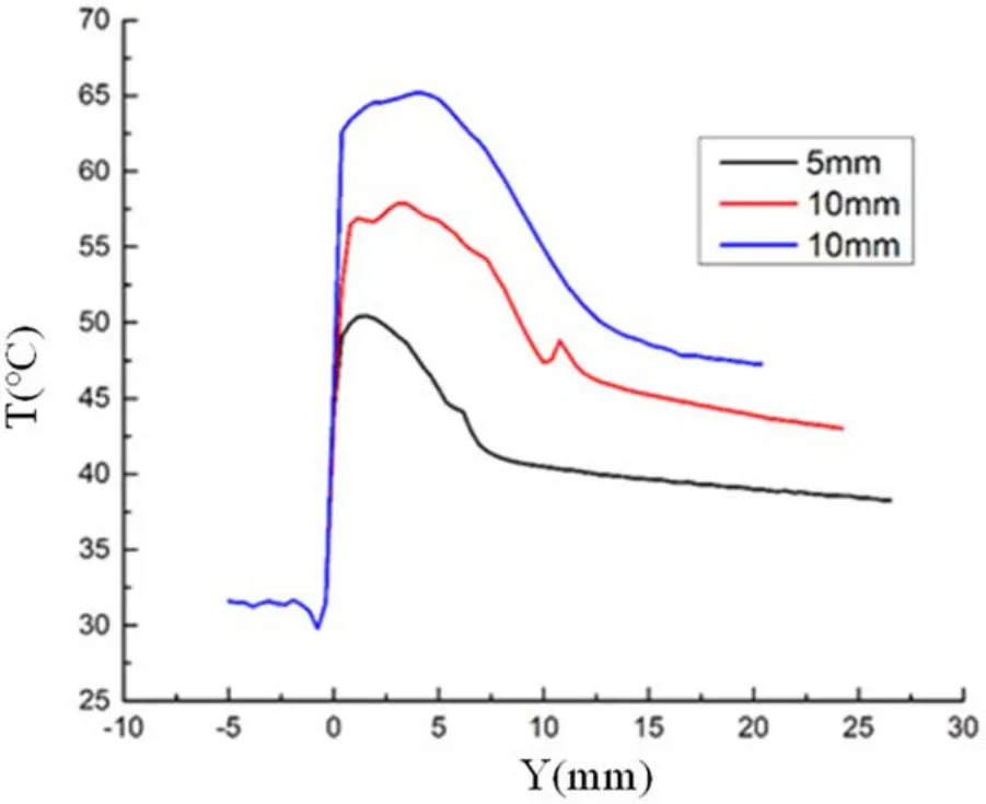
Figure 24.Changes of surface temperature along the Y-axis at X = 30 mm at different covered electrode widths (t = 120 s).
Figure 22 shows the surface temperature distribution of different covered electrode widths when the discharge time is 120 s.It can be seen that when the actuation parameters remain unchanged, increasing the electrode width can increase the surface temperature of the dielectric layer.The results in figures 23–25 also confirm this conclusion.The width of the covered electrode limits the extension of the discharge filament so that the length of the discharge filament does not exceed the width of the covered electrode.Therefore,under the actuation parameters in this experiment, increasing the width of the covered electrode will increase the injection energy,and the energy converted into heating the wall surface will also increase,resulting in a higher surface temperature of the dielectric layer.
When the voltage and frequency are constant, as the covered electrode width is wider, the discharge filament is longer,and the single pulsed energy is higher.The rising and falling edges have little effect on the single pulsed energy,and the single pulsed energy is the highest when the pulsed width is 500 ns.The longer the covered electrode width, the higher the single pulsed energy, the greater the range and intensity of the flow field and temperature field after discharge.

Figure 25.Variation of surface temperature with time at point A(X = 30 mm, Y = 4 mm) at different covered electrode widths.
4.Conclusion
NS-DBD plasma actuation is an active flow control method commonly used to control flow separation.Many characteristics and control mechanisms of NS-DBD plasma actuation,including discharge characteristics and induced flow field characteristics, have been deeply studied.For the high-frequency NS-DBD, it is found that its thermal effect is more obvious, and it has a good effect in the field of plasma antiicing.This paper tests the plasma discharge characteristics of NS-DBD under high frequency conditions, which provides a reference for anti-icing research.
According to the influence of pulsed voltage peak,pulsed actuation frequency, and covered electrode width on NSDBD discharge characteristics, induced flow field characteristics, and infrared radiation thermal characteristics, the rules of surface DBD on nanosecond pulsed are analyzed.The conclusion is as follows: there exists NS-DBD in the process of pulsed voltage rising and falling, and the air is heated rapidly and the shock wave and jet with lower velocity are induced.The direction of the induced jet is greatly affected by various parameters, and the nanosecond pulsed actuation is not only simple rapid heating but also has the effect of volume force.The covered electrode width will affect the potential distribution during the discharge process, and then affect the extension process of the plasma discharge filament,and the discharge area will be restricted by the electrode width.Increasing the peak value of the pulsed voltage can significantly increase the actuation intensity, and the plasma discharge area is significantly increased.Increasing the pulsed actuation frequency can increase the number of discharges per unit time.Both will cause more energy input, and the temperature rising effect will be more obvious.The surface temperature rising of the dielectric layer is closely related to the amount of input energy.The more the input energy, the more obvious the surface temperature rising effect of the dielectric layer.The surface temperature distribution is directly affected by different discharge patterns, and the temperature rising is more obvious in the area with strong discharge and more concentrated filaments.
Acknowledgments
This paper was supported by the National Key R&D Program of China (No.2019YFA0405300) and National Natural Science Foundation of China (Nos.51907205 and 12002363).
猜你喜欢
杂志排行

Plasma Science and Technology的其它文章
- Numerical studies of the influence of seeding locations on D-SOL plasmas in EAST
- On the stability of small-scale ballooning modes in axisymmetric mirror traps
- Viscous effects on plasmoid formation from nonlinear resistive tearing growth in a Harris sheet
- Microwave preionization and electron cyclotron resonance plasma current startup in the EXL-50 spherical tokamak
- FEQ: a new flux coordinates based equilibrium solver including both magnetic axis and separatrix
- Dispersion and damping rate of Langmuir wave in space plasma with regularized Kappa distributed electrons