The Swirl Distortion Flow Field Simulation Technology Based on S-shaped Inlet
2022-01-11JialeWangBangqinChengLuningFengJunLiYaozeYao
Jia-le Wang Bang-qin Cheng Lu-ning Feng Jun Li Yao-ze Yao
(Aeronautics Engineering College,Air Force Engineering University)
Abstract:With the wide application of S-shaped inlet in advanced aircraft,the swirl distortion generated by Sshaped inlet has attracted more and more attention.In order to investigate the characteristics of the swirl distortion at the outlet of S-shaped inlet,we present a swirl distortion generator that enables simulate the swirl flow field at the outlet of Sshaped inlet.The results show that the swirl distortion generator simulates the target flow field with high accuracy,and the error of the average swirl Angle on the aerodynamic interface plane(AIP) is 1.12°.The influence of the Mach number on the swirl distortion generator is negligible.With the development and mixing of the airflow downstream,the strengthof theswirldecreases.
Keywords:Swirl Distortion;S-shaped Inlet;Swirl Distortion Screen;Numerical Simulation;Distortion Generator;CFD
0 Introduction
In order to meet the requirements of stealth performance,more and more advanced fighters adopt S-shaped inlet[1-2].However,when the S-shaped inlet is doing maneuver,the swirl distortion will occur,which will cause engine surge,resulting in the incompatibility of the inlet with the engine[3-4].
During the ground test of the European tornado fighter,there was no incompatibility between the inlet port and the engine.However,during the flight test[5],the engine experienced a serious surge.This accident made people pay more attention to the research on the swirl distortion.After investigation,it was found that the S-shaped inlet adopted by the aircraft generated high intensity swirl under specific flight conditions,which eventually led to the accident.
In order to study the effect of the swirl flow generated by S-shaped inlet on the performance of the engine,the swirl distortion field must be obtained first.There are three main methods to obtain the distorted flow field:guide vane method,delta wing method and swirl chamber method.However,the above three methods of generating distorted flow field all have their limitations.The swirl distortion generated by them can only produce a bulk swirl and paired swirl,and only basic research can be carried out,so it is impossible to simulate the swirl distortion generated by the S-shaped inlet in the actual flight process.
Some research has been conducted to find a method that can reproduce any swirl distortion.Govardhan[6]designed a vane type swirl distortion generator,which is similar to the inlet guide vane of the engine.Jiang jian[7-8]from Nanjing University of Aeronautics and Astronautics has designed a vane type vortex distortion generator,which produce different swirls by adjusting blade configuration and layout.Sheoran and Bouldin[9-10]has designed a cyclone chamber generator,which can format bulk swirl and twin swirl.However,it is difficulty to precisely control the flow field generated by cyclone chamber generator.
The swirl distortion generator designed in this paper can simulate the swirl flow at the outlet of S-shaped inlet.The ultimate purpose is to accurately reproduce the complex swirl flow field based on the method proposed in this paper,which lays a foundation for exploring the influence of the swirl flow on engine performance.
1 Evaluation of Swirl Distortion
In this paper,the swirl distortion is quantified and evaluated by SAE.The definition of swirl Angle is as follows[11]:

Uθ:The circumferential velocity component at some point on AIP.
Ux:The axial velocity component at some point on AIP.
In this paper,sector swirl (SS),swirl intensity (SI),swirl directivity (SD) and swirl pairs (SP) is adopted to descript swirl flow field.SS,SI and SP are defined in terms of averaged value,intensity is similar to the circumferential pressure distortion descriptors in ARP 1420.Descriptor related to radial intensity in the total pressure distortion element is replaced by SD.What’s more,more details about swirl distortion descriptors can be found in SAE’s AIR 5686 report.
1.1 Sector Swirl
Eqs.(2)~ (5) are used for the calculation of the sector swirl on the monitoring ring.

1.2 Swirl Intensity
Equation (6) is used for the calculation of the swirl intensity on the monitoring ring.

For convenience of calculation,equation (6) is simplified into equation(7)in this paper.

1.3 Swirl Directivity
Equation (8) is used for the calculation of the swirl directivity on the monitoring ring.

Similarly,for convenience of calculation,equation(8)is simplified into equation(9)in this paper.

1.4 Sector Swirl
Equation (8) is used for the calculation of the swirl pair on the monitoring ring.

Similarly,for convenience of calculation,equation (10)is simplified into equation(11)in this paper.

2 Design Method
To design the swirl distortion generator,the target swirl field must be obtained first.The swirl reference line and blade reference line are designed based on the target swirl field.Then,according to the velocity vector of the target swirl field,the parameters of each blade shape of the distortion generator can be obtained.Finally,the model can be created in Solidworks.The design method of swirl distortion generator is divided into the following steps.
1)Getting the target swirl field.
2) Designing cyclone reference line and arrange the blade reference line.
3) Determining blade parameters according to the consistency and the velocity of the target swirl field.4)Designing support structure.5)Solidworks modeling.
2.1 Getting the Target Swirl Field
Firstly,the M2129 S-shaped inlet,which is a diffusion inlet with circular section,is chosen as research object in this paper.The geometric structure of M2129 is shown in Fig.1.There are two constant sections with a length of 342.8mm and 100mm respectively and one transition section.In this paper,AIP is set at the outlet plane.
ANSYS ICEM is employed in this work to divide and calculate the structural grid.The structured meshing strategy applied to divide the grid.The thickness of the first layer of the near-wall grid is 1mm,and the height ratio is 1.1,which generated 6,937,158 cells for full computational domain.SST model was adopted for turbulence model.The mesh of the M2129 is shown in Fig.2.

Fig.2 Mesh of the M2129 for CFD simulation
ANSYS CFX was used for calculation,total temperature,total pressure and air flow angle were used as the inlet boundary condition in the calculation.In this paper,total temperature is 287.2K,the total pressure is 101.1kPa at inlet interface and the static pressure is 82.7kPa at outlet plane.The wall condition is adiabatic and non-slip boundary condition.
2.2 Designing Cyclone Reference Line and Arrange the Blade Reference Line
CFX tool was employed to simulate the internal flow of M2129,and the velocity vector,which is shown in Fig.3,was obtained.

Fig.3 The velocity vector diagram of M2129
According to the target swirl field,the blade reference line can be set.It is found that when the blade is placed perpendicular to the streamline,the efficiency of generating swirl is the highest.
Based on the velocity vector diagram shown in Fig.3 the blade reference line is set.The blue line represents the cyclone reference line and gray line represents the blade reference line.As is shown in Fig.4,two swirl reference lines are set,and several points are set on the swirl reference line according to the distribution of velocity vector filed.Eighteen blade reference line are drawn according the points on the swirl reference line,and three feature points are set on each blade reference line to cover the entire swirl velocity vector field.
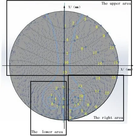
Fig.4 Schematic diagram of blade line and feature point position
To illustrate the specific position of each feature point,the velocity vector diagram is divided into three area,the upper,right and lower area.As shown in Fig.4,the points in each region were numbered respectively.Because the designed swirl distortion generator is symmetrical in both left and right,the unilateral point is taken as an example to illustrate.Finally,73 characteristic points were arranged in the swirl distortion field,including 15 points in the upper area,15 points in the right area and 8 points in the lower area.
According to the coordinates,the parameters needed can be obtained from the calculation results of M2129 inlet,then the swirl angle and other blade shape parameters can be determined according to the extracted velocity vector.Finally,swirl distortion generator model can be established by Solidworks.
2.3 Determining Blade Parameters
Once the distribution of the blade reference line is obtained,the geometric parameters of blade need to be determined.As is shown in Fig.5,NACA-A4K6 arc line was applied to the blade profile,and the spacing of curves was 2 mm.In order to determine the function relationship of the airflow angle with the installation angle,the plane cascade with a chord length of 50mm was calculated by setting boundary conditions in CFX.The results are shown in Fig.6.The function relationship of the airflow angle with the installation angle can be expressed by equation(13).

Fig.5 Blade of swirl distortion screen

Fig.6 Output turning angle as a function of angle of installation
The vector field of vortex velocity at the outlet section is obtained based on the calculation results of S-shaped inlet of M2129,and the velocity of the required points is extracted from the calculation results.The airflow angle of each characteristic point is calculated according to equation (12),and then the installation angle is determined according to the airflow angle by equation (13).In this paper,the blade consistency is set to 1,and the chord length and installation angle of each blade type at the feature point could be finally determined.

2.4 Designing Support Structure
There are two main principles for designing supporting structures:
1) Meeting the requirements of strength,stiffness and stability;
2) The supporting structure should minimize the impact on the calculation results.
Based on the two principles mentioned above,two blades with chord length of 15mm,thickness of 2mm and 0 degree installation angle were designed as supporting structures based on swirl reference line.
2.5 Solidworks Modeling
The blade profile of each feature point was drawn in Solidworks.The blade is generated by linear interpolation and supporting structure is added last.Finally,as is shown in Fig.7 the model is established.

Fig.7 CAD model
3 Numerical Methodology
As is shown in Fig.8,the calculating model is divided into three parts:front segments,distortion segments and rear segments.The diameter of the calculation model is 152.4mm,the lengths of the front segments,distortion segments and rear segments are 100mm,40mm and 300mm.
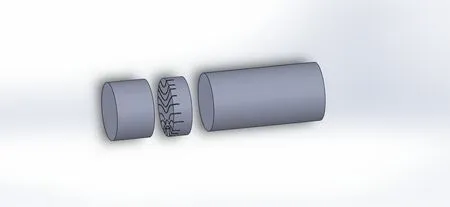
Fig.8 The calculating model
The unstructured tetrahedral hybrid grid is used in this paper because the complex blade structure.The thickness of the first layer of the near-wall grid is 0.04,the height ratio is 1.1 and the boundary layer is set to 6 layers,which generated 10 million cells for full computational domain.As is shown in Fig.9.

Fig.9 Mesh of swirl distortion generator
The boundary conditions are as follows:the total pressure is 101.1kPa and total temperature is 287.2K at inlet interface,the static pressure is 82.7kPa at outlet plane,the intake direction is axial.The computational domain is shown in Fig.10.AIP is set at the downstream of the distortion segment and its distance from the exit of the distortion segment is 152.4mm.
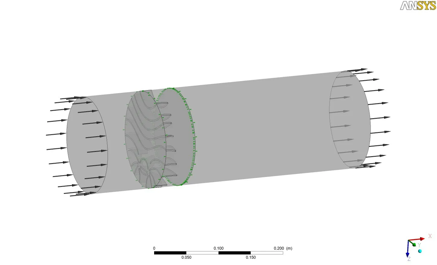
Fig.10 Computational domain
The three-dimensional CFD solver employed in this work was the commercial software Fine which is a part of the software package NUMECA.The swirl velocity vector field and swirl angle contours picture generated by the distortion generator are shown in Fig.11.
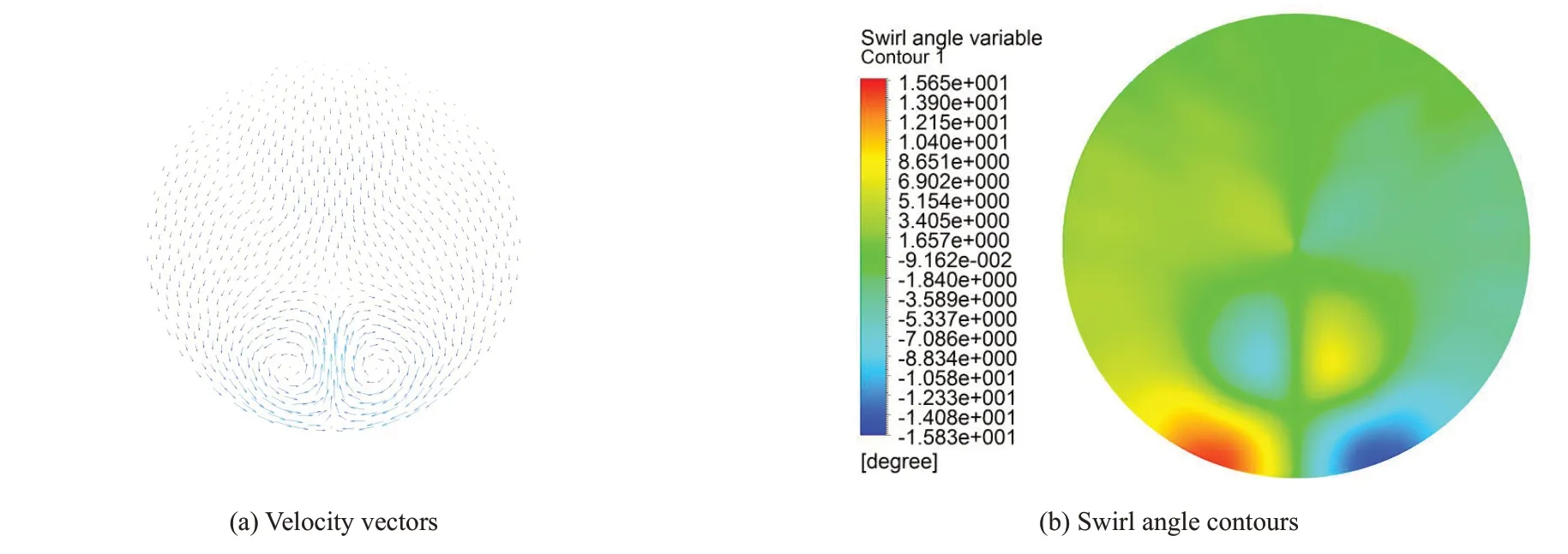
Fig.11 Velocity vectors and swirl angle contours
4 Results
In this paper,for convenience,the target flow field is called design flow field and the flow field generated by the distortion generator is called simulation flow field.In order to compare the consistency of the design and simulation flow field,Firstly,the swirl angle contours of two AIPs is compared.Then,the influence of Mach number on the flow filed produced by distortion generator is studied.Finally,the swirl distortion evaluation index introduced above was used to analyze the flow field on the two AIPs.
4.1 Evaluation of Swirl Distortion
In order to analyze and study the distortion of the flow field,as is shown in Fig.12(a),three monitoring rings with radiusR1=0.57R0,R2=0.73R0,R3=0.9R0were set.The swirl angle on the three monitoring rings of two AIPs is shown in the Fig.12(b)~(d).
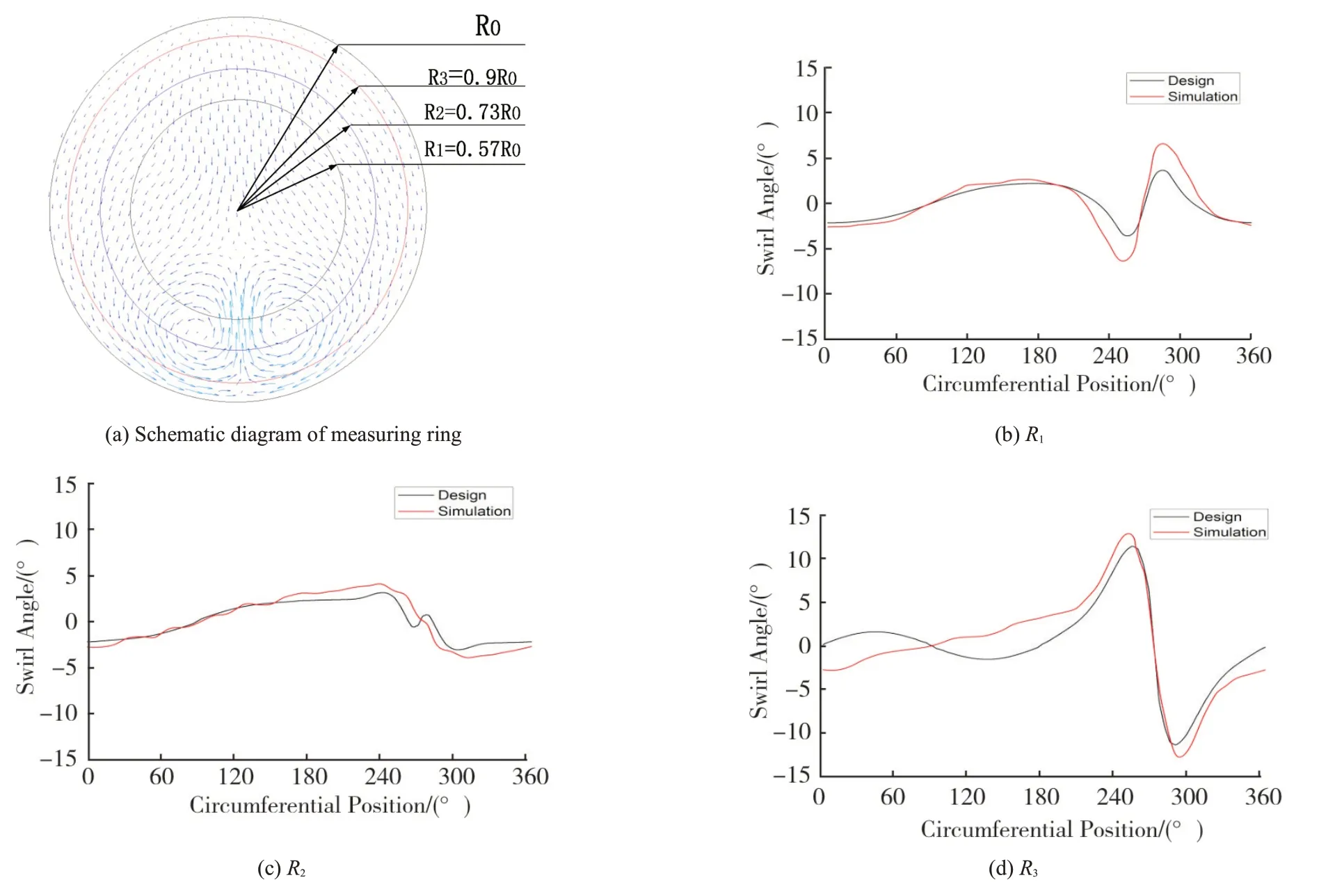
Fig.12 The swirl Angle on the three monitoring rings of two AIPs
The result shows that:The average deviation of the swirl angle on three monitoring rings is 0.99°、0.67°、1.71°,and the overall average deviation is 1.12°.Due to the structure in the third monitoring ring is complex and the third monitoring is proximity to the wall,the swirl error is largest in the third monitoring ring.
4.2 Mach Number Effect
To study the influence of airflow Mach number on the simulation flow field,the reverse pressure at the outlet of the rear section of the model was set as 70kPa,80kPa and 90kPa respectively,the total pressure is 101.1kPa and total temperature is 287.2K at inlet interface.Under these three conditions,the Mach number are 0.578,0.472 and 0.336.
As is shown in Fig.13,Mach number has little influence on the simulation flow field.Under three Mach number,the maximum swirl angle of the simulation flow field is 15.1°,-15.98°;16.09°,-15.98°;15.85°,-15.83°.

Fig.13 Velocity vectors and swirl Angle contours under three Mach number
Under three Mach numbers,the swirl angle on the three monitoring rings of two AIPs is shown in the Fig.14.The conclusions can be obtained:The Mach number have a little effect on the swirl angle,and the influence can be ignored in the range of 210°to 330°.In the full circumferential range,when the Mach number of the airflow is closer to the Mach number of the target flow filed,the error between the swirl angle obtained by the distortion generator and the swirl angle of the target flow filed is smaller.
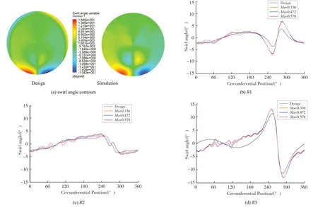
Fig.14 The swirl angle on the three monitoring rings
4.3 Comparison of Swirl Distortion Evaluation Indexes
Four distortion evaluation criteria mentioned above was employed to describe the flow field quantitatively.Sector Swirl,Swirl Intensity,Swirl Directivity and Swirl Pair is described by Fig.15~Fig.18 respectively.What’s more,in each picture,the left diagram represents the design flow field,and the right one represents simulation flow field.It can be seen intuitively that the design flow field is highly similar to the simulation flow field.

Fig.15 Sector Swirl

Fig.16 Swirl intensity
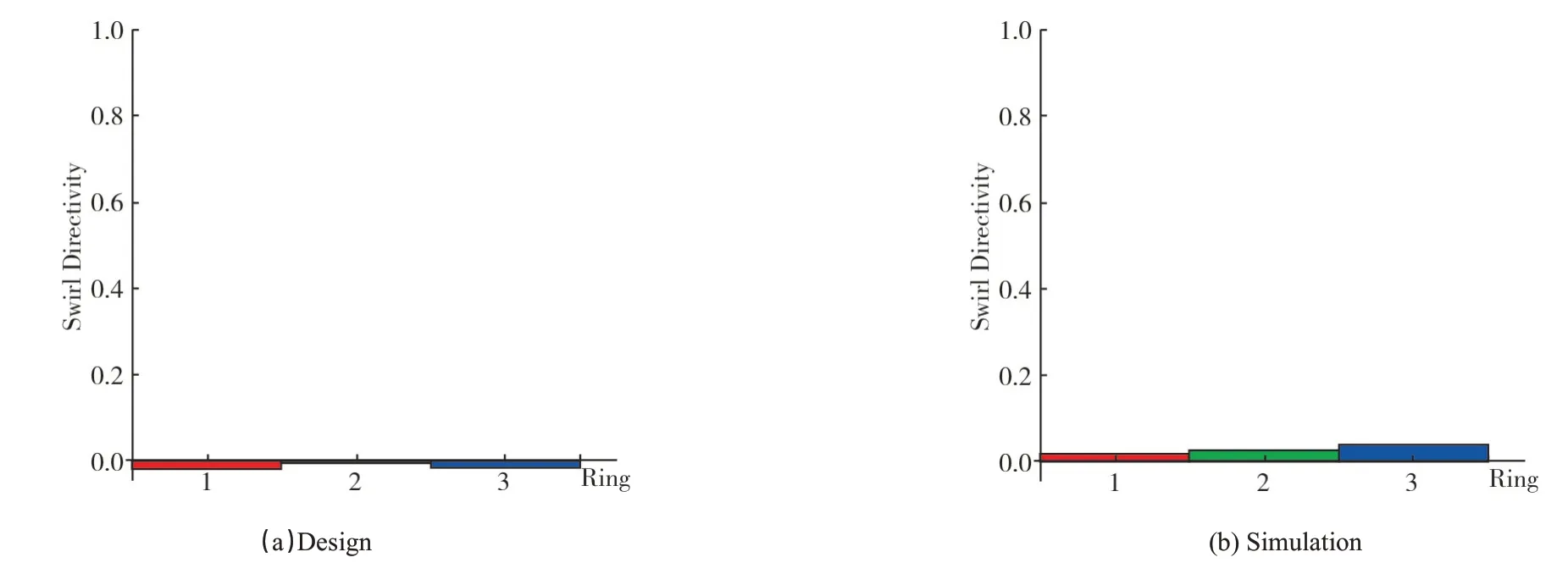
Fig.17 Swirl directivity

Fig.18 Swirl pair
The result shows that:
a) The SS of the simulation flow field is larger than design flow field in R1 and R2,but they are highly similar to each other in R3.it is find that he SS increases with the increase of the radius,which is the same as the variation trend of swirl angle.
b) The conclusion obtained from the SI is similar to the SS and need not to repeat here.
c) The SD close to 0 both the simulation flow field and design flow field,which means that there is a pair of equal in numerical but opposite vortices exit on monitoring ring.
d) The SP close to 1 both the simulation flow field and design flow field,which means that there is a pair of equal in numerical but opposite vortices exit on monitoring ring.This is consistent with the actual situation.
5 Conclusions
In this paper,a new design method was proposed to design a swirl distortion generator.By comparing and analyzing the design flow field and the simulation flow field,it is found that the new design method is effective.The following conclusions are also obtained:
1)The average error of the swirl angle on the three monitor ring is 1.12°.
2) The influence of Mach number on the swirl angle of the swirl distortion generator simulation is very small,and the influence can be ignored in the range of 210°to 330°.
3) It can reproduce any specific flow field,which breaks the limitation that most existing swirl distortion generator can only reproduce the general flow field such as bulk swirl and the twin swirl.
