High Energy Proton Radiation Effect on Flexible Thin-film Inverted Metamorphic Triple-junction Solar Cell
2021-12-15ZHANGYanqingZHOUJiamingLIUChaomingSHIXiangleiYANGYangJIAOXiaoyuSUNLijieWANGXunchunXIAOLiyiWANGTianqiHUOMingxue
ZHANG Yanqing, ZHOU Jiaming, LIU Chaoming,*, SHI Xianglei, YANG Yang, JIAO Xiaoyu, SUN Lijie, WANG Xunchun, XIAO Liyi, WANG Tianqi, HUO Mingxue
(1.Space Environment Simulation Research Infrastructure, Harbin Institute of Technology, Harbin 150001, China; 2.State Key Laboratory of Space Power Technology, Shanghai Institute of Space Power Sources, Shanghai 200245, China; 3.Microelectronics Center, Harbin Institute of Technology, Harbin 150001, China)
Abstract: A flexible thin-film GaInP/GaAs/InGaAs inverted metamorphic triple-junction (IMM3J) solar cell with conversion efficiency up to 32.47% (air mass (AM) 0, 1 367 W/cm2) was prepared to meet the requirements of space solar cells for lightweight and high efficiency. High-energy proton radiation (1, 3 and 5 MeV) was carried out to study its anti-irradiation performance. The SRIM simulation models indicate that 1, 3 and 5 MeV proton irradiation will cause approximately uniform damage in IMM3J cells. The light IV (LIV) results show that the degradation of the open-circuit voltage (Voc), short-circuit current (Isc) and maximum output power (Pmax) follows the logarithm change of the proton fluence. The fluences of different energy protons were converted into the displacement damage dose (DDD) through non-ionizing energy loss (NIEL). The Voc and Pmax decrease with an approximative logarithmic change of DDD, while the Isc follows two different degradation behaviors. The spectral response tests prove that GaInP sub-cell has excellent anti-irradiation performance, but InGaAs (1.0 eV) sub-cell has the worst anti-irradiation resistance and is the current-limiting sub-cell during the 1, 3 and 5 MeV protons irradiation continuously.
Key words:IMM3J solar cell; radiation effect; displacement damage dose
1 Introduction
In order to complete space missions successfully, solar cells with higher efficiencies and particle irradiation tolerance are expected to be used in space power systems. GaInP/GaAs/InGaAs inverted metamorphic triple-junction (IMM3J) solar cells were studied and considered as next-generation space solar cells since their higher efficiency than that of the currently-used InGaP/GaAs/Ge triple-junction (TJ) space solar cells[1-3]. Besides, the semiconductor substrate will be removed and the IMM3J solar cell structure is transferred to a new substrate during the device fabrication process. It allows a flexible lightweight substrate to support cell structure, which leads to an increasing in the specific power on spacecraft power panels[4-5]. The weight of IMM3J solar cell layers mounted on film with 10-20 μm is 1/15 of TJ cell with Ge substrate[6]. Thin film IMM3J solar cells are also successfully prepared by dry-epitaxial lift-off technology[7].
However, initial performance is not the most important for solar cells to be used in aerospace. Maintaining excellent performance in harsh space environments is the prerequisite for aerospace applications. In other words, performance at end of life (EOL) is more important than begin of life (BOL)[8]. The radiation degradation characteristics of each sub-cell in a multi-junction structure are necessary for the research of multi-junction space solar cell. In the case of the IMM3J cells, the degradation characteristics of the GaInP and GaAs sub-cells are well understood because they are already adopted in TJ cell structure. The radiation resistance of InGaAs (1.0 eV) sub-cell has been verified by electron and proton with different energy irradiation[9-12]. In spite of the fact that the IMM solar cell is the most important candidate for next-generation space solar cells, its irradiation damage behaviors have not been adequately reported. The existing results indicate that the remaining maximum output power (Pmax) of IMM3J solar cell on Si substrate can reach 79% when the 1 MeV electron radiation fluence reaches 1×1015cm-2. The spectral response and photoluminescence (PL) amplitude analysis show that InGaAs(1.0 eV) sub-cell exhibits the most severe damage as a result of 1 MeV electron irradiation and the InGaAs (1.0 eV) sub-cell is the rate-limiting sub-cell during irradiation[12].
The remainingPmaxof IMM3J solar cell on the Si handle is 73.7% when the 10 MeV proton radiation fluence reaches 4.35×1012cm-2[13]. To predict the service life of IMM3J solar cell in space, the proton irradiation damage behaviors on thin film IMM3J solar cells need to be further researched.
In order to promote the aerospace application of flexible thin film IMM3J solar cells, the flexible thin film IMM3J solar cells will be irradiated with 1, 3, 5 MeV protons in this paper, and the degradation mechanism of their electrical properties in space environment will be studied by light IV(LIV) and spectral response tests.
2 Device under test and experimental setups
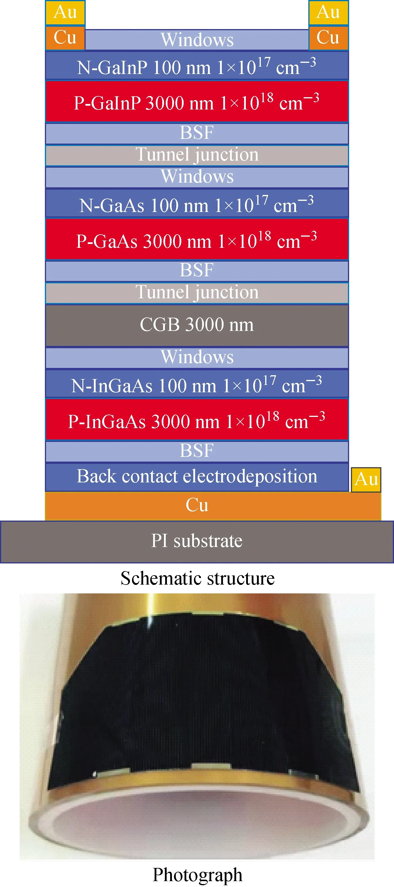
Samples are the flexible thin film IMM3J solar cells with the surface area of each cell is 43 mm×28 mm. All cells are epitaxially grown by metal organic chemical vapor deposition (MOCVD). The epitaxial layer of the cells grown on a GaAs substrate was successfully transported to the polyimide substrate with copper film. Electrodes for both p-type and n-type are firmly attached on the front surface to avoid wiring on the back. The base region is made of p-type material with a thickness of 3000 nm and a doping concentration of 2×1017cm-3. The emitter region is made of n-type material with a thickness of 100 nm and a doping concentration of 2×1018cm-3. Each sub-cell with window and back-surface field (BSF) is connected by a tunnel junction. A 7-order lattice mismatch gradient buffer layer structure with a thickness of 3000 nm is used to bridge the metamorphic GaAs and InGaAs(1.0 eV) cells.Fig.1 shows the configuration and schematic illustration of the GaInP (1.8 eV)/GaAs (1.41 eV)/InGaAs (1.0 eV) IMM3J solar cells.Fig.2 shows theI-Vcurve of the IMM3J solar cells at AM0. The short circuit current (Isc), the open circuit voltage (Voc), and the maximum output power (Pmax) of the non-irradiated sample are 210.66 mA, 3024.54 mV, and 528.99 mW, respectively.

Fig.1 Schematic structure and photograph of thin film IMM3J cell
1, 3, 5 MeV proton radiation was carried out through a tandem accelerator in Peking University, the radiation flux is 5×109cm-2·s-1, and the maximum radiation fluence is 5×1013cm-2. The electrical performance of the IMM3J solar cells was measured with the Spectrolab X25 Mark Ⅱ solar simulator under AM0 and 1-sun solar spectrum illumination. The spectral responses within 300-1800 nm were measured using the quantum efficiency measurement system (QEX10) of Photovoltaic Measurements Inc.

Fig.2 I-V curve of non-irradiated IMM3J cell at AM0
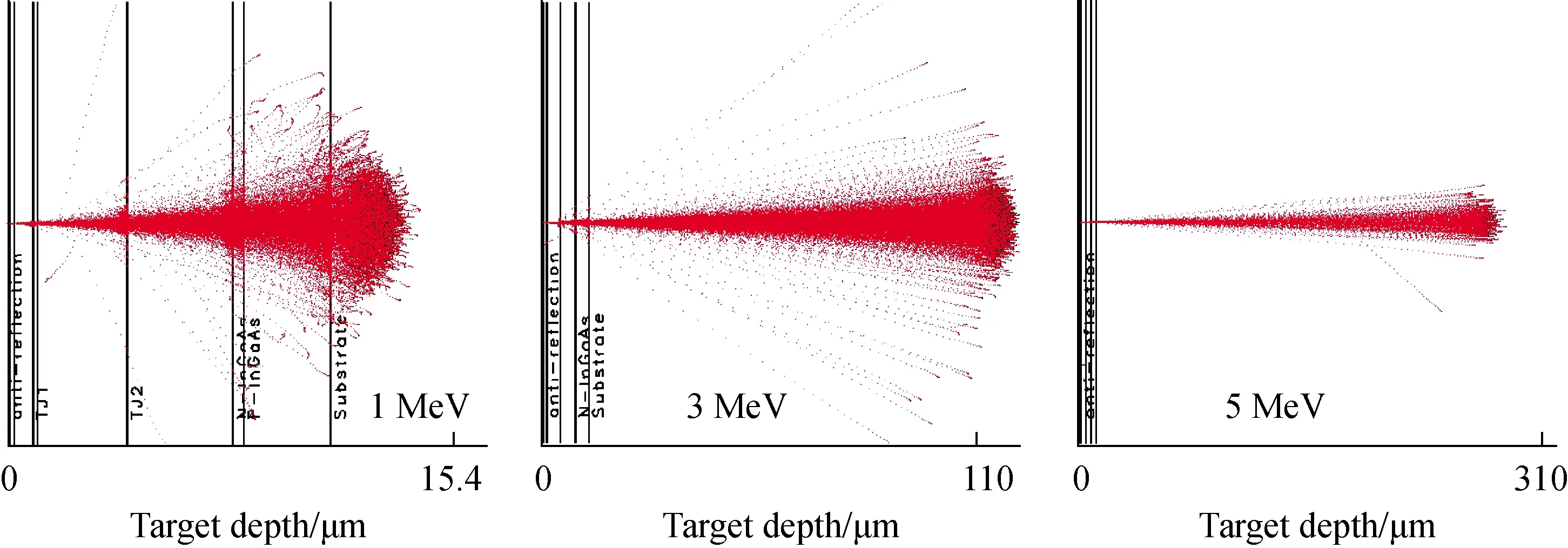
A SRIM simulation of the IMM3J solar cell structure was carried out using the SRIM-2008 software. The thickness of the material of each layer was set according to Fig.1a, and a GaAs substrate far exceeding the thickness of the IMM3J solar cell was set on the backside of InGaAs (1.0 eV) sub-cellsFig.3 and Fig.4 are the trajectories and particle deposition depths of different energy protons in the IMM3J solar cells. According to the SRIM codes, the majority of protons with 1-5 MeV energy are stopped within the substrate, which imply the approximately uniform displacement damage is caused in the IMM3J solar cell due to 1-5 MeV proton radiation.

Fig.3 Trajectories of different energy protons

Fig.4 Particle deposition depths of protons with different energy
3 Results and analyses
Fig.5 shows the degradation caused by protons with 1, 3 and 5 MeV on the remaining factors ofVoc,Isc, andPmax. The degree of electrical damage increases and the damage rate decreases gradually when the proton fluence increases up to 5×1013cm-2. To determine the degradation law ofIsc,Voc, andPmax, the experimental data were fitted as a function of the logarithm of the proton fluence (φ):
P=1-cPlg(1+φ/φ0P)
(1)
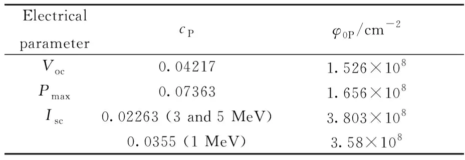
Where,Prepresents each electrical property (Isc,Voc, andPmax);cPis the corresponding degradation rate, it represents the magnitude of the performance damage caused by 1-5 MeV proton radiation;φ0Pis the critical damage fluence of the solar cell, it indicates the speed of electrical damage caused by irradiation. Both ofcPandφ0Pare used to measure the impact of charged particle radiation damage on solar cell performance degradation, which is related to the solar cell material, structure, and doping concentration. The fitting curve is also displayed in Fig.5. ThecPandφ0Pfitting constants of IMM3J solar cells are given in Table 1. The fitting curve and the experimental data show a good degree of coincidence. TheIscdecreases more than theVoc. ThePmaxdecreases the most when the fluence increases, which is because its proportionality to the product of the voltage and the current.
It is obvious that the proton radiation damage decreases with the increase of energy of 1,3 and 5 MeV. The displacement defects introduced by charged particle radiation are the main reason for the decline in electrical performance. Non-ionizing energy loss (NIEL) can be used to measure the ability of charged particles to introduce displacement defects in the material. Table 2 shows the NIEL values of 1-5 MeV protons in GaInP, GaAs and InGaAs (1.0 eV) calculated by screened relativistic (SR) NIEL calculator[14]. The NIEL values of three kinds of sub-cell materials decrease with the increase of the radiation proton energy at 1-5 MeV. Larger NIEL means more displacement defects introduced by charged particle radiation.

Fig.5 Remaining factors of Voc, Isc and Pmax with fluence at 1, 3 and 5 MeV protons

Table 1 Fitting results of degradation factors for Voc, Isc, and Pmax after irradiation by 1, 3, 5-MeV protons

Table 2 NIEL of GaInP, GaAs and InGaAs (1.0 eV) irradiated by 1, 3 and 5 MeV protons
The NIEL in Table 2 was used to convert the proton fluence with different energy into displacement damage dose (DDD).Fig.6 is the curve of remainingVoc,IscandPmaxas a function with DDD. It is shown that the relationship between remainingVoc,IscandPmaxand DDD follows formula (1). The fitted curves are also shown in Fig.6, and the fitted results are listed in Table 3. The remainingVocandPmaxfollow a single function with DDD, while the remainingIscof IMM3J solar cells irradiated by the 1 MeV proton, but that by the 3 and 5 MeV protons follow different functions. The most possible reason is that 1 MeV proton deposition depth is close to the base region of the InGaAs (1.0 eV) sub-cell and a part of protons deposite in the InGaAs (1.0 eV) base region, which is demonstrated in SRIM simulation. This is different from the uniform damage caused by the complete penetration of protons. The energy of protons loses faster at the end of the trajectory (near the deposited depth), it could cause more displacement damages. TheVocdegradation is affected by defects in junction regions, and there is almost uniform deposition in the three junction regions of the IMM3J solar cell. ThePmaxis affected by the voltage and current, but it shows obviousVocdependence.

Fig.6 Remaining Voc, Isc and Pmax with DDD

Table 3 Fitted results of degradation factors for Voc, Isc, and Pmax
The external quantum efficiency (EQE) curves of GaInP, GaAs and InGaAs (1.0 eV) sub-cells irradiated by 1, 3 and 5 MeV protons were obtained through the spectral response test, which is shown as the Fig.7. The EQE curve of each sub-cell gradually decreases when the proton fluence increases up to 5×1013cm-2. The EQE degradation of the GaInP sub-cell is not obvious until the proton irradiation fluence up to 5×1013cm-2, which proves its excellent irradiation resistance. However, the EQE curves of the GaAs and InGaAs (1.0 eV) sub-cells are significantly degraded, especially at the longer wavelengths. It is because that the defects introduced by proton irradiation uniform distribute in the active region. And the base region of cells is much thicker than the emitter region. As a result of the different lengths of diffusion path, the probability of photogenerated carriers at the bottom of the base region being trapped by defects is greater than that of the emitter and junction regions. The shorter wavelength photons will be absorbed by the upper material, while the carriers generated in the lower base region should originate from the longer wavelength photons. Therefore, the EQE exhibits a more sensitive decrease in long wavelength.
The short-circuit current density (Jsc) of each sub-cell was also obtained by spectral response test, which can be used to quantitatively characterize the degradation degree of each sub-cell.Fig.8 shows theJscof each sub-cell radiated by 1, 3 and 5 MeV protons with different fluences. It can be seen that the initialJscof GaInP, GaAs and InGaAs (1.0 eV) sub-cells is equivalent. Radiation defects will damage theJscof each sub-cell andJscdecreases as the radiation fluence increases. Low energy proton in the range of 1-5 MeV radiation will cause a greater decrease inJscat the same fluence, which is consistent with the conclusion of LIV. In addition, InGaAs (1.0 eV) sub-cell presents the minimum ofJscand the maximum degradation atJscamong the three sub-cells in proton radiation. It has the worst anti-irradiation performance and it always be the current limiting junction of the IMM3J solar cell. Normally, the sub-cell with the worst anti-irradiation performance is not the best choice as the current limiting junction. It will cause an obvious difference in the performance of space solar cells at the BOL and EOL.

Fig.7 EQE curves of IMM3J solar cell irradiated by 1, 3 and 5 MeV proton at different fluences

Fig.8 Jsc of three sub-cells in IMM3J solar cell irradiated with proton
4 Conslusion
This paper introduces a flexible thin-film IMM3J solar cell with a maximum conversion efficiency of 32.47%. 1, 3 and 5 MeV proton radiation experiments were carried out to study its anti-radiation performance. The SRIM simulation models indicate that 1, 3 and 5 MeV protons will cause approximately uniform damage in IMM3J solar cells and the proton with high energy will cause low electrical performance loss. LIV results show that the electrical properties (such asIsc,Voc, andPmax) decrease with the logarithmic change of proton fluence. The degradation ofVocis slightly more pronounced than that ofIscin IMM3J solar cells. Besides, the fluences of protons with different energy are converted into DDD through NIEL according to the DDD method. It is shown that theVocandPmaxdecrease with an approximative logarithmic change of DDD, while theIscfollows two different degradation behaviors. The reason is that more 1 MeV protons would be deposited in the base region of the InGaAs (1.0 eV) sub-cells, instead of penetrating the active region IMM3J solar cell completely. It would introduce more displacement defects. The deposited protons will introduce more displacement defects, resulting in a more decrease in theIscof the InGaAs (1.0 eV) sub-cell. In addition, the spectral response test illustrates that the EQE of each sub-cell decreases as the fluence increases. The damage degree of each sub-cell is different in the different wavelengths. The EQE curves of GaInP sub-cells show a decline in short wavelength, while that of the GaAs and InGaAs (1.0 eV) sub-cells show a serious decline in long wavelength. TheJscof each sub-cell indicates that the InGaAs (1.0 eV) sub-cell has the worst anti-radiation performance and is the current-limiting junction of the IMM3J solar cell continuously during the 1, 3 and 5 MeV protons irradiation.
杂志排行
原子能科学技术的其它文章
- H-1NF仿星器标准磁场位形分析与高能量离子运动轨道模拟
- 铀转化生产线含氟废水处理工艺设计
- 在线进样ICP-MS用于239Pu气溶胶活度浓度连续监测技术研究
- Degradation Characteristic of Proton Irradiated 8T CMOS Image Sensor
- Comparative Experimental Study on Space Electrostatic Discharge Effect and Single Event Effect of 130 nm SOI D Flip-flop Chains
- Effects of Electron Irradiation at Different Energy and Fluences on Electrical Properties of InP HEMT Structure
