Research on Thermal Management Control Strategy of Electric Vehicle Liquid Cooling Battery Pack
2021-11-26ZhenhuaLi
Zhenhua Li
Sangdun New Energy Technology Co., Ltd., Xiangtan, Hunan, 411202, China
ABSTRACT Due to the risk of thermal runaway in the charging and discharging process of a soft packed lithium battery pack for electric vehicles, a stamping channel liquid cooling plate cooling system is designed, and then the heat dissipation problem of the battery pack is solved through reasonable thermal management control strategy.Using computational fluid dynamics simulation software star-CCM+, the thermal management control strategy is optimized through simulation technology, and the temperature field distribution of battery pack is obtained.Finally, an experimental platform is built, combined with experiments, the effectiveness of the thermal management control strategy of the cooling system is verified.The results show that when the battery pack is in the environment of 25℃, the maximum temperature of the cooling system can be lower than 40℃, the maximum temperature difference between all single batteries is within 5℃, and the maximum temperature difference between inlet and outlet coolant is 3℃, which can meet the heat dissipation requirements of the battery pack and prevent out of control heat generation.
Keywords: Electric vehicle Power battery liquid cooling system Computational fluid dynamics Analogue simulation
1.Introduction
At present, due to the problems of environmental protection and energy security, the state vigorously develops new energy electric vehicles, and the core technology of electric vehicles is lithium-ion battery pack.How to prevent the battery pack from thermal runaway and spontaneous combustion under charge and discharge conditions is an urgent research hotspot.When the lithium-ion battery pack is working, a large amount of heat is generated due to continuous high current charging and discharging.If the heat is not dissipated in time, the excessive temperature and temperature difference will seriously affect the power performance and service life of the electric vehicle[1].Aiming at the risk of thermal runaway in the charging and discharging process of a soft packed lithium battery pack for electric vehicles, a stamping channel liquid cooling plate cooling system is designed, and then the heat dissipation problem of the battery pack is solved through reasonable thermal management control strategy; Using the computational fluid dynamics simulation software star CCM +, the thermal management control strategy is optimized through the simulation technology.Finally, the experimental platform is built.Combined with the experiment, the effectiveness of the thermal management control strategy of the cooling system is verified.
2.Battery Pack Cooling System Design
The battery pack consists of 20 modules, which are placed in parallel in upper and lower layers, with 8 columns in the lower layer and 2 columns in the upper layer; each module contains 32 17.5ah soft packed lithium batteries, which are formed in series and parallel.The battery pack adopts the stamping channel liquid cooling plate cooling system, which is mainly composed of heat conducting silica gel pad, inlet and outlet water pipe and stamping liquid cooling plate; the three stamping liquid cooling plates are connected in series.The heat is transferred between the liquid cooling plate and the battery module through the heat conducting silica gel pad, and the coolant is 50% ethylene glycol water mixed solution.See Figure 1 and Figure 2.
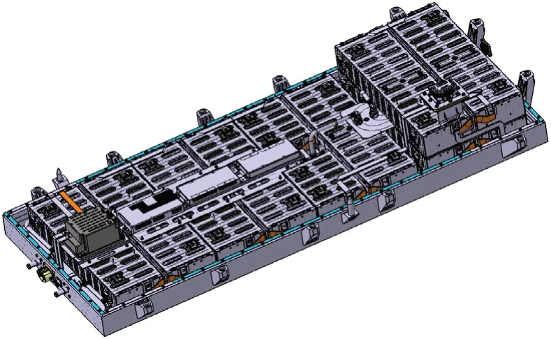
Figure 1.battery module system

Figure 2.liquid cooling plate cooling system
3.Simulation Calculation of Battery Pack Cooling System
3.1 Governing Equations of Computational Fluid Dynamics
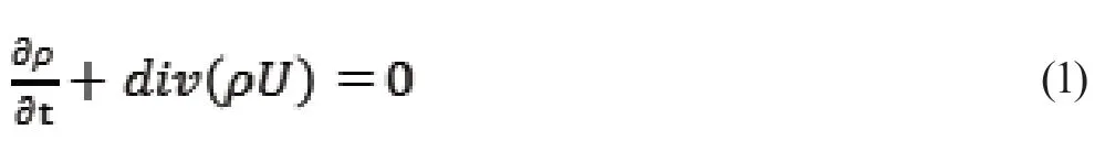
In the process of fluid flow, three conservation laws are observed: the law of mass conservation, the law of momentum conservation and the law of energy conservation.In computational fluid dynamics[2,3], there should be: mass conservation equation, momentum conservation equation and energy conservation equation.
(1) Mass conservation equation
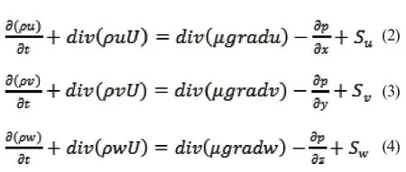
(2) Momentum conservation equation
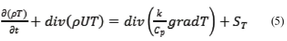
(3) Energy conservation equation
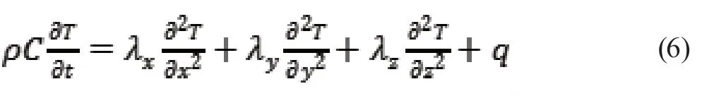
(4) Differential equation of heat conduction in battery
3.2 Thermal Management Simulation Strategy
Working condition 1: Under the ambient temperature of 25 ℃, the initial temperature of the system is 26.5 ℃, the coolant is not turned on.The battery pack 1C is charged (the heating power of the cell is 2W), until the maximum temperature at the probe point rises to 36 ℃.
Working condition 2: When the maximum temperature of the probe point rises to 36 ℃, battery pack 1C continues to charge (the heating power of the cell is 2W), and at the same time, turn on 15 ℃ coolant 10L/min until the total charging time is 3243S.
Working condition 3: When the total charging time is 3243s, the battery pack 1C-0C continues to charge (the heating power of the cell is 0.38W), and the 15 ℃ coolant is opened for 10L/min.The battery pack 1C-0C current drop charging time is 1440S.
Working condition 4: When the 1C-0C current drop charging of the battery pack is completed, the battery pack starts to stand.At the same time, open 15 ℃ coolant 10L/min until the maximum temperature of the cell probe point is reduced to 30 ℃.It takes 405S for the maximum temperature of the battery pack to drop to 30 ℃ from the beginning of stand.
Working condition 5: When the maximum temperature of the probe point of the cell is reduced to 30 ℃, the battery pack continues to stand for 75s, and the 15 ℃ coolant 10L/min is closed at the same time.
Working condition 6: After standing, turn off 15 ℃ coolant 10L/min at the same time, battery pack 1C discharge (heating power of cell is 2W), and it takes 1710S until the maximum temperature at the probe point rises to 38 ℃.
Working condition 7: When the maximum temperature of the probe point of the cell rises to 38 ℃, turn on the 15 ℃ coolant for 10L/min, and the battery pack 1C continues to discharge for 1890S (heating power of the cell is 2W) until the discharge of the cell is completed.
Working condition 8: When the 1C discharge of cell is completed, continue to turn on 15 ℃ coolant for 10L /min, and the battery pack stands for 240S.
Working condition 9: After the stand of battery, battery pack 1C charge for 1800S (heating power of battery cell is 2W) and keep the 15℃ coolant open for 10L / min.
3.3 Boundary Condition
Between the box body and the external environment is convective heat exchange; between the coolant and liquid cooling plate is convective heat exchange and heat conduction; between the battery module and heat conducting silica gel, heat conducting silica gel and liquid cooling plate are heat conduction, and the rest parts and the air in the box body are natural convective heat exchange.See Table 1 for material property parameters of each part of the simulation model.
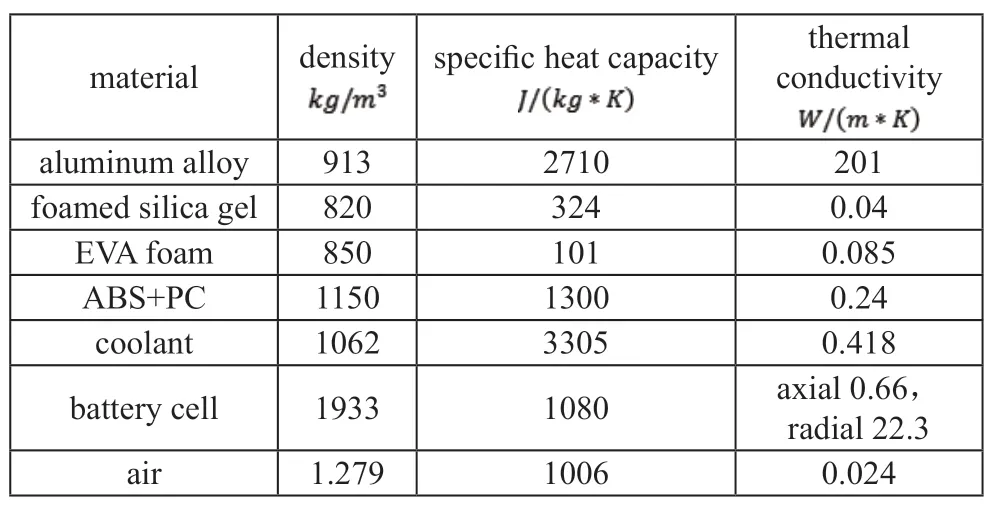
Table 1.material parameters of each part of the model
3.4 Analysis of Simulation Results
As shown in Figure 3, along the flow path of the coolant, the temperature of the liquid cooling plate increases gradually, and the temperature of the battery pack also increases gradually.The coolant takes away heat in the process of flow, which also causes the temperature difference between battery packs.In Figure 4, in order to display the temperature difference between different battery packs, 29 temperature detection points are set to monitor the top, middle and bottom temperatures of the battery respectively.In Figure 5, according to the analysis, during the whole working condition, the maximum temperature of the cooling system can be lower than 40 ℃; the maximum temperature difference of all arranged probe points is within 5 ℃, and the maximum temperature difference of inlet and outlet coolant is 3℃, which can meet the heat dissipation requirements of the battery pack and prevent thermal runaway.

Figure 3.cloud diagram of temperature field of liquid cooling plate

Figure 4.cloud diagram of battery pack temperature field
4.Experimental Verification of Temperature Field of Battery Pack
4.1 Experimental Equipment and Temperature Distribution Scheme
In order to obtain the cooling effect of the battery pack under actual working conditions, an experimental platform needs to be built for testing, as shown in Figure 6.The selection of the detection position of the temperature point is consistent with that in the simulation calculation, which is convenient for comparative analysis.It is proposed to distribute 29 T-type thermocouples on the surface of the battery pack.Figure 7 shows that the charging and discharging system of the power battery is TECHPOW-600, and the water-cooled circulator system is a multifunctional GE522A.After the establishment of the experimental platform, set the coolant inlet temperature to 15 ℃, and adjust the temperature of the constant temperature chamber to 25℃, and start the charging and discharging equipment to charge and discharge the battery pack according to the thermal management simulation strategy.

Figure 5.curve of coolant temperature at detection points and outlet

Figure 6.experimental platform
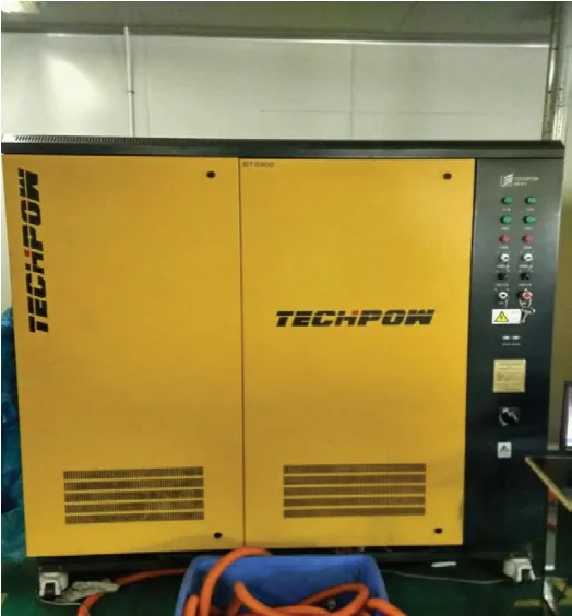
Figure7.charging and discharging equipment
4.2 Analysis of Experimental Results
Figure 8 is the curve of each temperature sensor monitored during the experiment, and Figure 9 is the temperature of each sampling point of the battery pack at the time 3376S during the experiment.
Figure 8 shows that the experimental results are basically consistent with the simulation data.The battery pack does not have too high temperature points, and the temperature distribution is in good consistency.As can be seen from Figure 9, the highest temperature point is T3 sampling point, which is located at the bottom of the lower battery, and the temperature is 35.8 ℃; The lowest temperature point is T12, which is located in the middle of the upper battery near the water inlet side; and the temperature is 30.8 ℃.The maximum temperature difference of each monitoring point of the battery pack is 5℃.
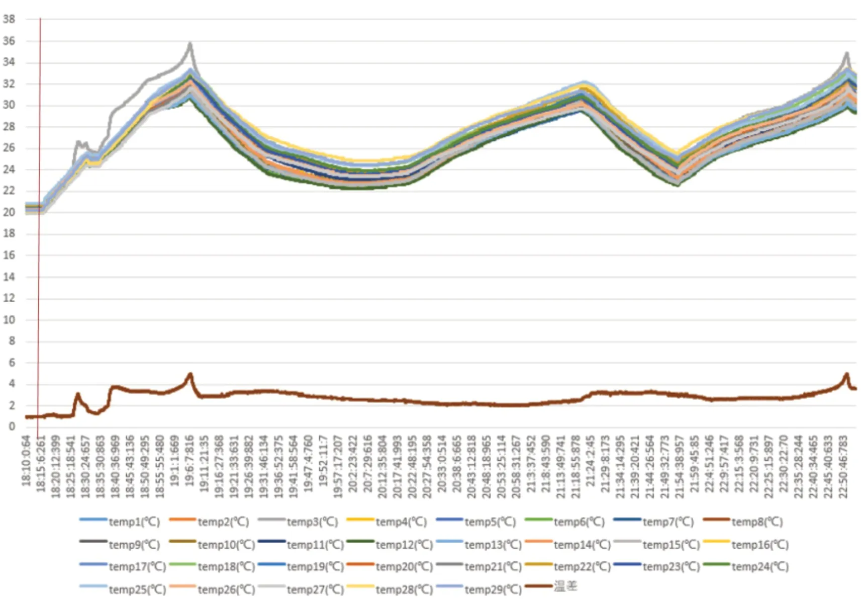
Figure 8.curve of each sampling point during the experiment
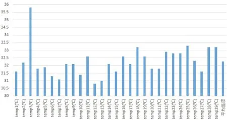
Figure 9.temperature of each sampling point at the time3376S
5.Conclusions
Aiming at the risk of thermal runaway in the charging and discharging process of a soft packed lithium battery pack for electric vehicles, a stamping channel liquid cooling plate cooling system is designed, and then the heat dissipation problem of the battery pack is solved through reasonable thermal management control strategy.Using the computational fluid dynamics simulation software star CCM+, the thermal management control strategy is optimized by simulation technology, and the temperature field distribution of the battery pack is obtained.Finally, an experimental platform is built to verify the effectiveness of the thermal management control strategy of the cooling system.The results show that when the battery pack is in the environment of 25℃, the maximum temperature of the cooling system can be lower than 40℃, and the maximum temperature difference between all single batteries is within 5 ℃, and the maximum temperature difference between inlet and outlet coolant is 3℃, which can meet the heat dissipation requirements of the battery pack and prevent thermal runaway.
杂志排行

Modern Electronic Technology的其它文章
- Research on Direct Torque Control of Permanent Magnet Synchronous Motor for New Energy Vehicles
- A 4-element Rectangular Microstrip Patch Antenna Array
- Overview of Vehicle AEB
- A Review of Traffic Conflict Avoidance Methods at Intersection Using Vehicle-Infrastructure Cooperation System
- Design of a Submarine Pipeline Inspection Robot System Based on CT Technology