A 4-element Rectangular Microstrip Patch Antenna Array
2021-11-26DemouCaoZhihanZhangKaiKangQiaoyuWang
Demou Cao Zhihan Zhang Kai Kang Qiaoyu Wang
Electrical and Computer Systems Engineering Department, Monash University, Melbourne, Victoria, Australia
ABSTRACT Patch antennas are small in size and suitable for microwave transmission, so they are widely used in small portable wireless devices.Multiple patch antennas are connected together to form an array antenna.Compared with the patch antenna, the array antenna has a higher directivity gain and can achieve better transmission performance.In this project, I will test the single patch antenna first, and then move to 2×1 antenna array.Finally, built a 2×2 antenna array, test and record their performance respectively.
Keywords:Antenna gain Antenna efficiency Directivity Return loss Transmission loss Far-field Radiation pattern
1.Introduction
CST Microwave Studio is a powerful electromagnetic field simulation software.In this design project, I built a 2×2 antenna array with cooper and FR-4 materials, then tune the parameters and test the model to achieve a quite good performance at my assigned frequency(2.7411GHz).
2.Background
Directional property of an antenna is defined in term of ‘directive gain’.Directive gain is ratio of the normalised power intensity in a particular direction to the average normalised power intensity such as from an isotropic radiator[1,2].Directivity is the maximum of directive gai n:A nten na gain = directivity times efficiency:.The antenna efficiency is defined as, whereis loss resistance,Rris radiation resistance.The total efficiency of an antenna is the radiation efficiency multiplied by the impedance mismatch loss of the antenna, when connected to a transmission line or receiver (radio or transmitter).The E-plane and H-plane are reference planes for linearly polarized waveguides, antennas and other microwave devices[3,4].
For a linearly-polarized antenna, E-plane is the plane containing the electric field vector and the direction of maximum radiation.The electric field or “E” plane determines the polarization or orientation of the radio wave[5,6].H-plane is the plane containing the magnetic field vector and the direction of maximum radiation[7].In a radio antenna’s radiation pattern, the main lobe is the lobe containing the higher power.This is the lobe that exhibits greater field strength[8].The beamwidth of the antenna is the width of the main lobe, usually specified by the half power beam width (HPBW), the angle encompassed between the points on the side of the lobe where the power has fallen to half (-3 dB) of its maximum value[9].The antenna bandwidth is defined as the band of frequency over which the performance of the antenna remains within an acceptable limit.Reflection coefficient S11 is a ratio of the reflected power and incident power[8-10].Through return loss in dB, we can calculate S11 by using: S11=.The greater value of S11, the worse transmission performance.
3.Simulation Results
3.1 Patch Antenna Design
3.1.1 Initial Parameter Setting
Before built the model, we need set the value of all parameter we will use.First, calculating the value of necessary parameters should do first.MATLAB code is shown in Figure 1, and all of the parameters are setting as shown in Table 1[11].
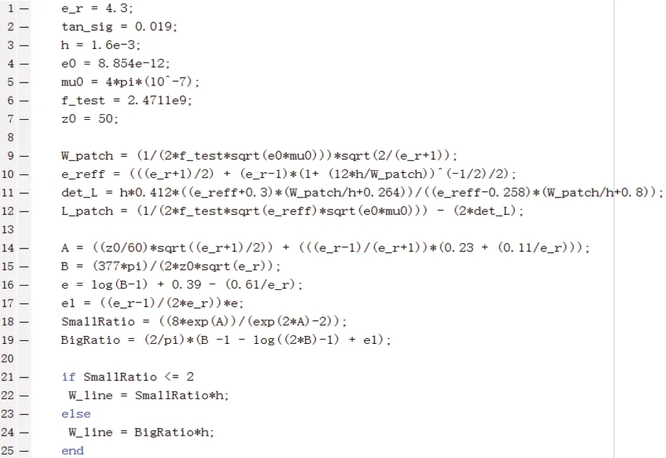
Figure 1.MATLAB code for calculate parameters
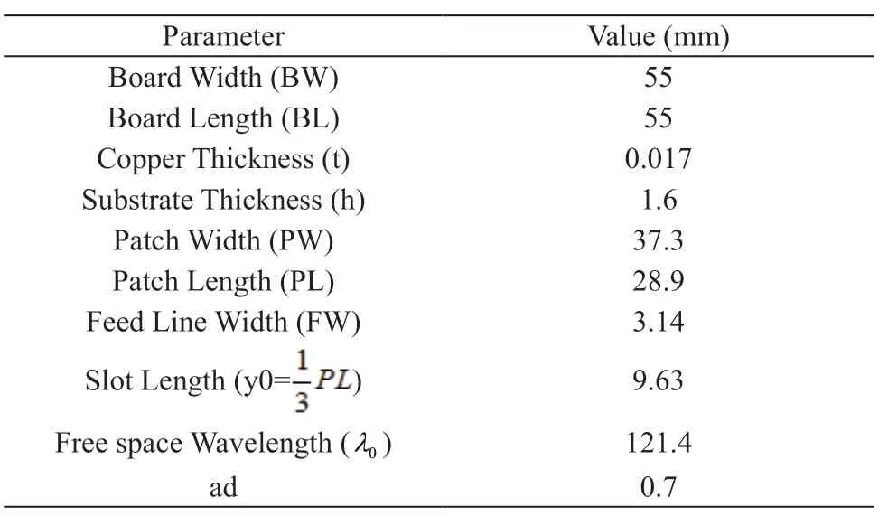
Table 1.Initial parameters
3.1.2 Optimize S11
First we should use parameter sweep to step change the y0 to change the S11, make sure S11is better than -30 dB around 2.4711 GHz.Then we fix the value of y0, and tune the PL value to shift the peak of S11plot at resonant frequency.The finally goal in this stage is to achieve that the S11at resonant frequency is greater than -30 dB[12-15].My S11result is -44.015 dB and shown in Figure 2.The final value of slot length is y0=8.03, the patch length is PL=28.2mm and achieve the S11 is -44.015dB at frequency is 2.4764GHz.Also, the directivity is 6.384dBi which was improved by optimizing the slot length and patch length, and better than 6dBi[12-15].The far field result is shown in Figure 3.The Polar result of 90 degree and 0 degree are shown in Figure 4 and Figure 5 respectively.
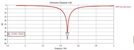
Figure 2.Patch antenna S11 result by tuning y0 and PL
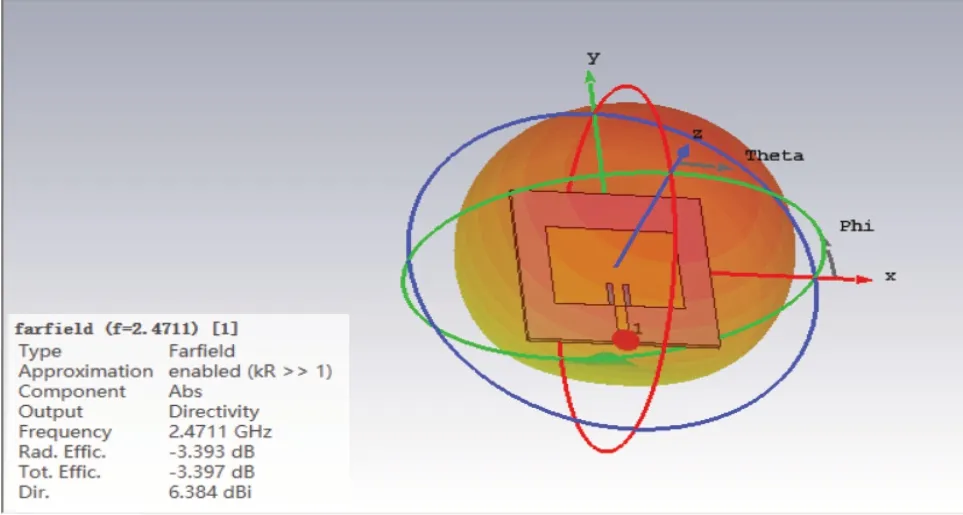
Figure 3.Patch antenna Directivity result in farfield
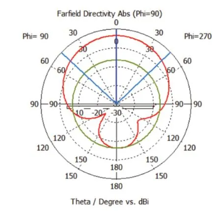
Figure 4.Farfield Directivity (Phi=90)
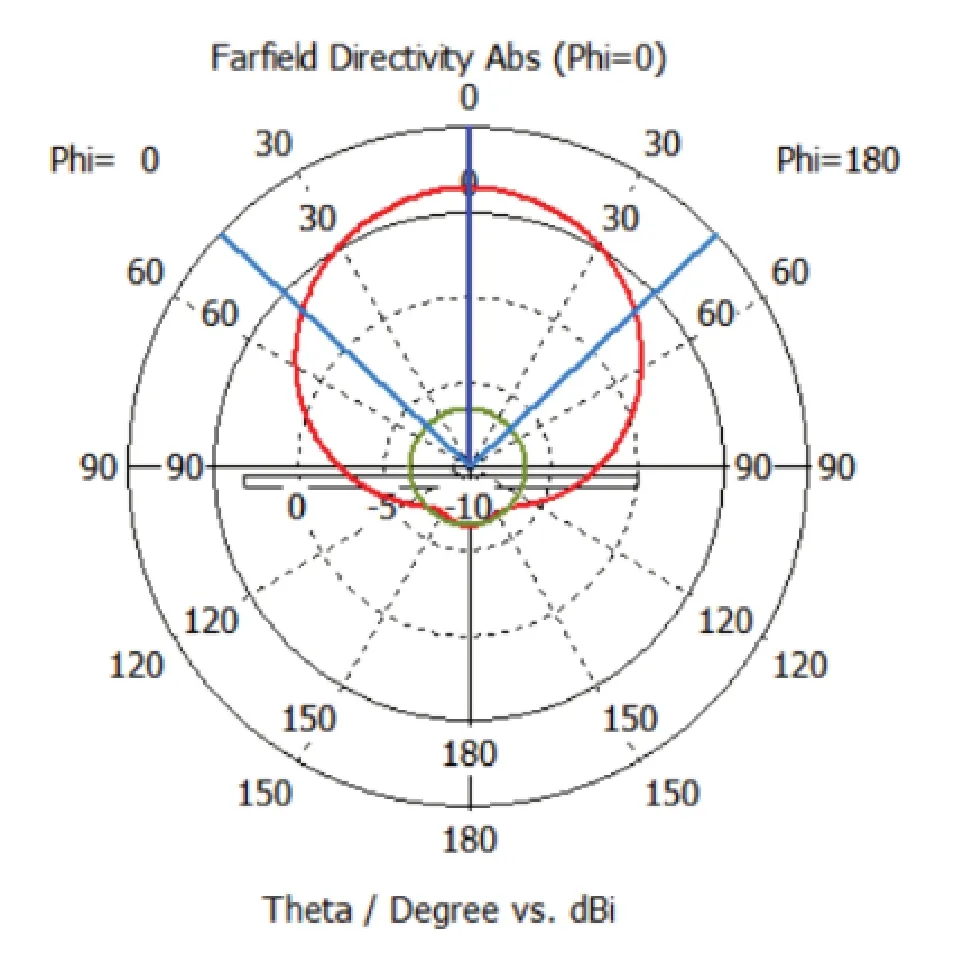
Figure 5.Farfield Directivity (Phi=0)
3.2 2×1 Antenna Array Design
At beginning of this part, a 3dB power divider should be constructed.First set the ground plane and substrate length as d=ad×wavelength to make sure the size of power divider will match the 2×1 Antenna array size.Through the Macros function in CST to calculate the 70.7Ω transmission line width and length[13].The transmission line width is 1.64mm and line length is 17.279mm.Then, use one and two 50Ω line connected with the transmission line as input line and output line respectively.The plot of S-parameters is shown in Figure 6.
After built the power divider, connected it with 2×1 antenna array and repeat the step of tuning as previous part.Through my optimizing, the Directivity of the 2×1 antenna array is 9.705dBi, which is better than 9dBi[12-15]and shown in Figure 7.The S11is -49.207dB at 2.4742GHz and the Realized Gain is 5.579dBi (better than 5dB) shown in Figure 8 and Figure 9 respectively.
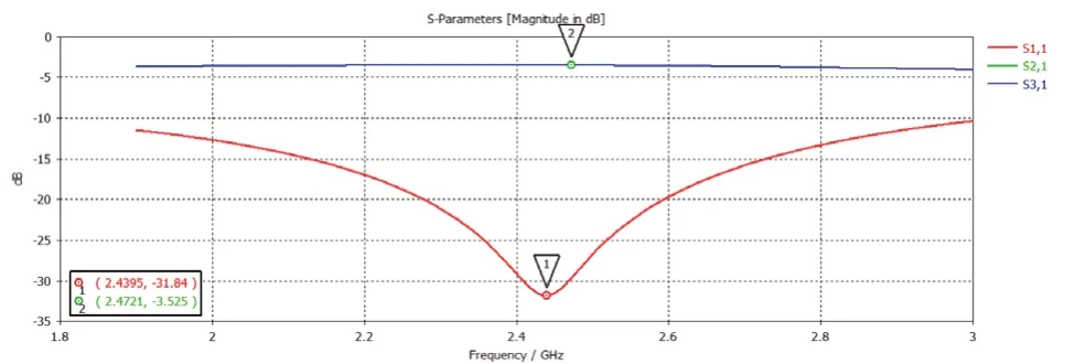
Figure 6.S-parameters plot of Power Divider
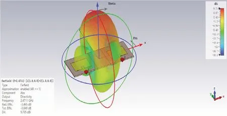
Figure 7.Two Patch Antenna Directivity result in far-field

Figure 8.2×1Antenna array S11 result
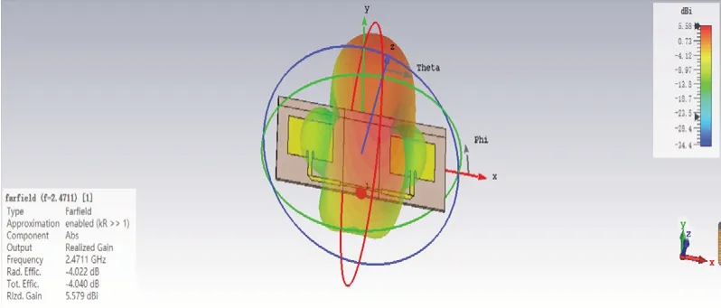
Figure 9.2×1Antenna array Realized Gain result in farfield
3.3 2×2 Antenna Array Final Integration
This is the final part of designing, and I have built a completed 2×1 Antenna array, to integrate a 2×2 Antenna array, translate and copy the 2×1 Antenna array with a distance (0.70λ[13]) first, then copy the Power Divider and add it.Also, antenna tuning is necessary to ensure the S11 is better than -30dB at resonant frequency(2.4711GHz±10MHz) and achieve the Realized Gain is greater than 7dB.The tuning results of S11 are -41.402dB at 2.472GHz, which is shown in Figure 10.Meanwhile, the Realized Gain is 8.013dBi and shown in Figure 11.
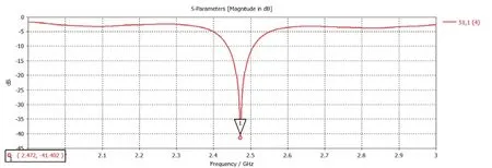
Figure 10.2×2 Antenna array S11 result in far-field
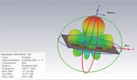
Figure 11.2×2 Antenna array Realized Gain result in farfield
For final integration, delete the upper labelled transmission line in the Y direction, construct a meandered transmission line, and the dimensions should be defined as Figure 12 shows.Finally, observing the far-field Polar plot of Directivity at Phi=90 when altering the phase shift as 22.5°, 45° and 90° in this case.The result is shown in Figure 13.All the simulation parts are finished at this point.

Figure 12.Parameters of meandered line setting

Figure 13.Farfield result with phase shift =22.5°, 45°and 90°
4.Measured Results
In this part, measured S11and antenna gain of a 2-element array and a 4-element array antenna with MiniVNA equipment.The measurement of antenna gain is calculated by Friis Transmission Equation.Figure 14 shows when connect with DET, and S11is -24.44 dB at 2.4333 GHz.Figure 15 illustrates connect with DUT, S11is -25.27 dB at 2.4327 GHz.Figure 16 shows S21of 2-element antenna array is -15.15 dB at 2.4474 GHz.

Figure 14.S11 vs Frequency connect with DET

Figure 15.S11 vs Frequency connect with DUT

Figure 16.S21 vs Frequency of 2-elements antenna array
The gain of the 2×1 antenna array is calculated using the Friis Transmission Equation[16],{32.45 +20log102.4474 +20log100.2 -15.15 +1.5}=6.2973 dB
Now I measure the return loss and transmission loss of Power Divider and 4-elements antenna array with power divider.Figure 17 shows the plot of return loss with frequency of power divider, and at 2.4305GHz, S11= -18.60dB, Figure 18 shows the return loss of 4-element array with power divider is -15.69 dB at 2.3599GHz.

Figure 17.S11 vs Frequency of power divider
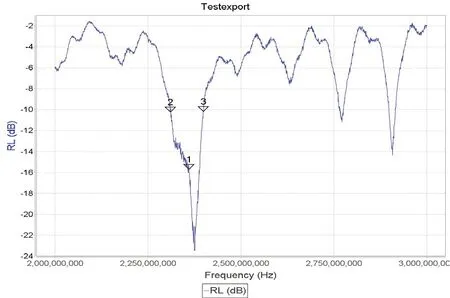
Figure 18.S11 vs Frequency of 4-element array with power divider
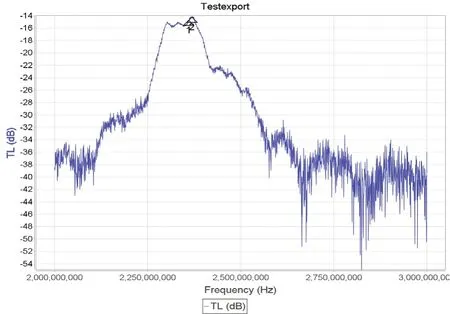
Figure 19.S21 vs frequency of 4-element array with power divider
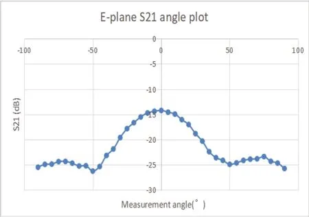
Figure 20.E-plane radiation pattern
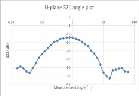
Figure 21.H-plane radiation pattern
The gain of the 4-element antenna array with power divider is calculated using the Friis Transmission Equation[1 6],{32.45 +20log102.3599 +20log100.2 - 1 4.72 +1.5 1.5}=6.3542 dB
The radiation pattern of antenna array is measured by rotating 5°every time between -90° and 90° to obtain the value of S21for both E-plane and H-plane.
5.Conclusions
Overall, the slot length and patch length are the critically important parameters which have a significant effect on antenna performance.With the increase of the number of patch antennas, we can see that the gain and directivity of antennas is increasing.Therefore, increasing the number of patch antennas can achieve better transmission performance, and achieving more usages in our life.In my design, I also achieve the 2×2 antenna array has benefits over the single patch antenna as theory.From the observation of transmission loss and realized gain both in simulation results and measured results, the 2×2 antenna array has a higher gain and lesser transmission loss.
It is also clear that, for the 2×2 antenna array design, we can find the simulation result on CST platform is better than the measured result on MiniVNA.Probably, the reason is in practical, there are more loss exist, and also the microstrip patch antennas generally have quite narrow bandwidth which result in very sensitive to the environment setting and the accuracy of placement.In CST platform, the line loss is constant and materials are all have a uniform density, which is an ideal situation for antenna, so the result is better.When measuring the transmission loss of the antenna array, the requirements for frequency matching are very high, because the antenna bandwidth we use is very narrow, and the same frequency must be ensured to achieve 100% signal transmission.
杂志排行
Modern Electronic Technology的其它文章
- Research on Direct Torque Control of Permanent Magnet Synchronous Motor for New Energy Vehicles
- Overview of Vehicle AEB
- A Review of Traffic Conflict Avoidance Methods at Intersection Using Vehicle-Infrastructure Cooperation System
- Design of a Submarine Pipeline Inspection Robot System Based on CT Technology
- Research on Thermal Management Control Strategy of Electric Vehicle Liquid Cooling Battery Pack
